

Bosch MMD 302 Original Instructions Manual
MMD 302
de
Originalbetriebsanleitung
Digital Multimeter
en
Original instructions
Digital Multimeter
fr
Notice originale
Multimètre numérique
es
Manual original
Multímetro digital
it
Istruzioni originali
Multimetro digitale
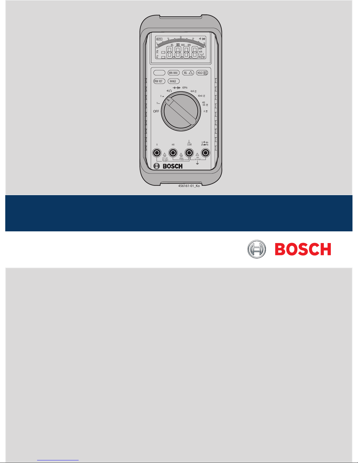
MIN MAX REL HOLD
RANGE
PRW RST
H
OFF
V
V
ADPHz
4mA
40mA
400
mA
A
A
mA
V
Hz
MAX
CAT.III 600V
DC
AC
REL MAXMIN
MEM
mVA
C n u F
MK Hz
0
10
20
30
40
AUTO
H
456161-01_Ko
COM
MAX
MAX
400mA
FUSED
FUSED
10 A cont.
20 A 30sec.

1 689 979 642 2014-11-03
|
Robert Bosch GmbH
| MMD 302 | 15
en
Contents English
1. Symbols used 16
1.1 In the documentation 16
1.1.1 Warning notices -
Structure and meaning 16
1.1.2 Symbols in this documentation 16
1.2 On the product 16
2. Safety instructions 16
2.1 Risk of electric shocks 16
2.1.1 Low voltages, high voltages 16
2.1.2 High voltages in hybrid vehicles and
electric vehicles as well as their
high-voltage components 17
2.2 Danger of fire, Danger of explosion 17
2.3 Danger of burning 17
2.4 Danger of tripping 17
2.5 Danger of injury, Danger of crushing 18
3. General Information 18
3.1 User profile 18
3.2 Application 18
3.3 Function description 18
3.4 Scope of delivery 18
3.5 Front View, operating elements and
connections 19
3.5.1 LCD 19
3.5.2 Blue function button 19
3.5.3 MIN MAX button 19
3.5.4 REL ∆-button 19
3.5.5 HOLD-button 20
3.5.6 PWR RST-button 20
3.5.7 RANGE-button 20
3.5.8 Measurement-mode switch 20
4. Connection and operation 20
4.1 Alternating and direct current
measurement 20
4.2 Acoustic continuity test and
resistance measurement 20
4.3 Capacitance measurement and
diode test 21
4.3.1 Capacitance measurement 21
4.3.2 Diode test 21
4.4 Frequency measurement 21
4.5 Current measurement 21
4.6 Possible uses of the protective
rubber cover 21
4.6.1 Single-handed multimeter 21
4.6.2 Measurement cables can be wrapped 22
4.6.3 Erecting 22
4.6.4 Protection 22
5. Maintenance 22
5.1 Cleaning 22
5.2 Spare parts and parts subject to wear 22
5.3 LCD difficult to read 22
5.4 0000 appears during current
measurement 23
5.5 Changing the batteries 23
5.6 Changing the fuses 24
6. Technical Data 24
6.1 General data 24
6.2 Measurement category as per EN61010 24
6.3 Meas. range, resolution and accuracy 25

1 689 979 642 2014-11-03
|
Robert Bosch GmbH
16 | MMD 302 | Symbols used
en
1. Symbols used
1.1 In the documentation
1.1.1 Warning notices - Structure and meaning
Warning notices warn of dangers to the user or people
in the vicinity. Warning notices also indicate the consequences of the hazard as well as preventive action.
Warning notices have the following structure:
Warning
symbol
KEY WORD – Nature and source of hazard!
Consequences of hazard in the event of failure to observe action and information given.
¶ Hazard prevention action and information.
The key word indicates the likelihood of occurrence and
the severity of the hazard in the event of non-observance:
Key word Probability of
occurrence
Severity of danger if instructions not observed
DANGER Immediate impend-
ing danger
Death or severe injury
WARNING Possible impending
danger
Death or severe injury
CAUTION Possible dangerous
situation
Minor injury
1.1.2 Symbols in this documentation
Symbol Designation Explanation
!
Attention Warns about possible property damage.
i
Information Practical hints and other
useful information.
1.
2.
Multi-step
operation
Instruction consisting of several steps.
e
One-step
operation
Instruction consisting of one step.
Intermediate
result
An instruction produces a visible intermediate result.
"
Final result There is a visible final result on com-
pletion of the instruction.
1.2 On the product
! Observe all warning notices on products and ensure
they remain legible.
Instructions for your personal safety and
for the protection of equipment/vehicle
components
2. Safety instructions
2.1 Risk of electric shocks
2.1.1 Low voltages, high voltages
Hazardous voltages occur in both the lighting
system and the electrical system of a motor
vehicle. If contact is made with live parts
(e.g. with the ignition coil), there is a risk of
electric shock from flashover voltages caused
by damaged insulation (e.g. ignition cables
which have been attacked by martens). These
apply to the secondary and primary sides of
the ignition system, the wiring harness with
connectors, lighting system (Litronic) as well
as connection to the vehicle.
Safety measures:
¶ Only connect to a properly grounded outlet.
¶ Only the enclosed or a tested power supply cable is
to be used.
¶ All extension cables must be fitted with shock-proof
contacts.
¶ Do not exceed the voltage limits as specified on the
connection cables.
¶ Any cables with damaged insulation must be re-
placed.
¶ Before connecting it to the vehicle, first connect the
product to the lighting mains and switch on.
¶ Before switching on the ignition connect the (B-)
cable to engine ground or the battery (B–) terminal.
¶ Always switch off the ignition before performing any
work on the electrical system of the vehicle. Intervention includes, for instance, connection to the
vehicle, replacement of ignition system components,
removal of equipment (e. g. alternators), connection
of equipment to a test bench.
¶ Wherever possible, tests and settings should always
be caried out with the ignition switched off and the
engine stationary.
¶ If tests or settings are carried out with the ignition
switched on or the engine running, care must be
taken not to touch any live parts. This applies to all
connection cables and leads as well as to connections of equipment to test benches.
¶ Test connections must always be made using suit-
able connectors (e.g. Bosch testing cable set or
vehicle-specific adapter cables).
¶ Make sure that all test connections are properly
plugged in and secure.
¶ Before disconnecting the (B-) cable from the engine
ground or battery (B–), switch off the ignition.
¶ Never open the enclosures.
Disposal
Dispose of used electrical and electronic
devices, including cables, accessories and
batteries, separately from household waste.
1 689 979 642 2014-11-03
|
Robert Bosch GmbH
Symbols used | MMD 302 | 17
en
2.2 Danger of fire, Danger of explosion
There is a risk of fire and explosion from fuels and fuel vapors when work is performed
on the fuel system or on the mixture control
system.
Safety measures:
¶ Switch off the ignition.
¶ Allow the engine to cool down first.
¶ Avoid naked flames and potential sources of sparks.
¶ Do not smoke.
¶ Collect any leaked fuel.
¶ Always ensure effective ventilation and suction when
working in closed areas.
2.3 Danger of burning
When working on a hot engine, there is a risk
of injury from burning if such components as
the exhaust gas manifold, the turbo-charger,
the Lambda sensor, etc. are touched or if
parts of the body come too close to them.
These components may be heated to tem-
peratures of several hundred degrees Celsius.
Depending on the duration of the exhaust
gas measurements, the sampling probe of the
exhaust gas measuring instrument may also
become extremely hot.
Safety measures::
¶ Always wear protective clothing, e.g. gloves.
¶ Allow the engine to cool down first. This also applies
to auxiliary heating systems.
¶ Keep connecting cables well away from all hot parts.
¶ Do not leave the engine running any longer than
necessary for the test or setting.
2.4 Danger of tripping
When conducting tests or making adjustments, the sensor and connection cables increase the risk of tripping.
Safety measures:
¶ Route the connecting cables such that any risk of
tripping up is prevented.
2.1.2 High voltages in hybrid vehicles and electric vehicles as well as their high-voltage components
If high-voltage components or high-voltage
wires are inexpertly handled, there is a risk of
fatal injury from high voltages and the possible transmission of current through the body.
¶ Deenergization is only to be performed by
a qualified electrician, a qualified electrician for specific tasks (hybrid) or a power
systems engineer.
¶ Work on vehicles with high-voltage com-
ponents is only ever to be performed in
a safe, deenergized condition by persons
with the minimum qualification "Trained to
perform electrical work".
¶ Even after deactivating the high-voltage
vehicle electrical system, the high-voltage
battery may still be live.
¶ Operating condition cannot be established
from any running noise, as the electric machine is silent when stationary.
¶ In gear positions "P" and "N" the engine
or electric motor may start spontaneously
depending on the charge of the high-voltage
battery.
Safety measures:
¶ Never open or damage high-voltage batteries.
¶ On accident vehicles, never touch high-voltage com-
ponents or exposed high-voltage wires before deactivating the high-voltage vehicle electrical system.
¶ Avoid contact with any high-voltage components
and high-voltage wires (orange sheathing) when in
operation.
¶ Secure against unauthorized renewed start-up
(e.g. by means of a padlock).
¶ Always wait at least 10 seconds after deactivating
the high-voltage system.
¶ Visually inspect the high-voltage components and
high-voltage wires for damage. The power systems
engineer responsible should always be immediately
notified of any irregularities, doubts or defects
found.
$ High-voltage components must never exhibit signs
of external damage.
$ The insulation of the high-voltage wiring must be
intact and undamaged.
$ Watch out for any abnormal deformation of the
high-voltage wiring.
 Loading...