

Bosch ISP-EM55FM-120 Quick Installation Manual
Safety
Danger!
Electricity
Injuries due to electricity are possible.
Switch off all electricity while installing
the product.
Do not open or modify this product, except if described in this manual.
Old electrical and electronic appliances
Electrical or electronic devices that are no
longer serviceable must be collected separately
and sent for environmentally compatible recycling (in accordance with the European Waste
Electrical and Electronic Equipment Directive).
To dispose of old electrical or electronic
devices, you should use the return and collection systems put in place in the country concerned.
Short information
This zone expander module integrates manual
conventional sensor technology (e.g. conventional magnet contacts) into the local security
network (LSN).
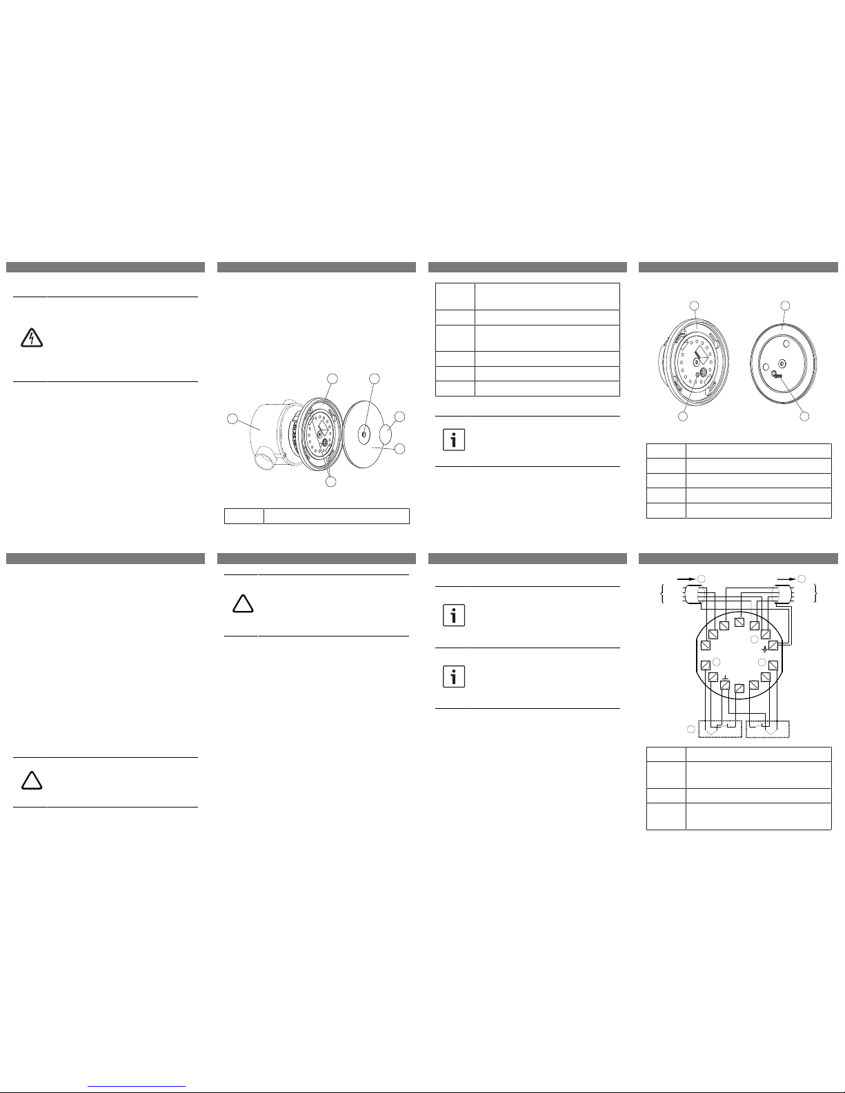
System overview
1
2 3
4
5
6
Fig.1: System overview
Element Description
1 Recessed socket (not part of the de-
livery)
2 Mount with PCB
3 Opening for housing cover fastening
screw
4 Adhesive seal
5 Housing cover
6 Opening for fastening screws
Mounting the zone expander module
Notice!
The recessed socket is not part of the
delivery. Use a recessed socket according to DIN 49073 part I.
How to mount the zone expander module
1. Connect the PCB.
2. Place the mount with PCB into a recessed socket and lock it in position using the two fastening screws.
Closing the zone expander module
3
2
1
4
Fig.2: Closing the zone expander module
Element Description
1 Mount with PCB
2 Housing cover
3 Insertion post
4 Opening for insertion post
How to close the zone expander module
1. To close the zone expander module, put
the housing cover onto the mount with
PCB while ensuring that the insertion
post (element 3 in figure above) on the
lower side of the housing cover fits into
the designated opening for the insertion
post (element 4 in figure above) on the
mount with PCB. Do not force the insertion post into any of the other openings.
2. Secure the housing cover with the housing cover fastening screw.
3. Put the adhesive seal onto the housing
cover fastening screw.
Connection
!
Caution!
Incorrect cabling
Incorrect cabling leads to malfunction
of the system.
!
Caution!
Cable length
Exceeding the permitted cable length is
not covered by CE declarations and
leads to malfunction of the system.
– Do not exceed the total cable length of
500m for the primary cables, the control
cables and the contact cables of EM 55,
KD55/1, NKK, NNK 100 2-wire, NVK and IC
400.
Permitted cable length of the primary cables
(PL)
– Maximum length of one unshielded cable:
3m
– Maximum length of all shielded cables: 500m
LSN connection
– Voltage supply can be fed-through (other-
wise free terminals for 0V/+U).
– Incoming and outgoing LSN can be swapped
over.
4-wire and 2-wire connections
Notice!
A mixed operation of a 4-wire connection at one of the primary outputs and
a 2-wire connection at the other
primary output is not permitted.
Notice!
For a 4-wire connection always use unshielded cables.
For a 2-wire connection always use
shielded cables.
4-wire connection (unshielded)
– Use a 4-wire connection with an unshielded
cable with a maximum length of 3 m and the
internal EOL resistor (e.g. for magnetic contacts).
– With an unshielded cable, do not connect
contacts with metallic enclosure.
LSN
aLSN1
bLSN1
0V
+U
LSN
aLSN1
bLSN1
aLSN2
bLSN2
0V
I1
I2
I3
I4
II5
I6
II1
II2
II3
II4
II6
RE1
RE2
PL1
PL2
RE1
RE2
I5
I7
+U
aLSN2
bLSN2
0V
+U
II7
1
2
2
3
4
4
Element Description
1 Terminal for fed-through voltage sup-
ply
2 LSN connection
3 4-wire connections, e.g. magnet con-
tacts (unshielded)
1 | 2 | 3 | 4 |
5 | 6 | 7 | 8 |
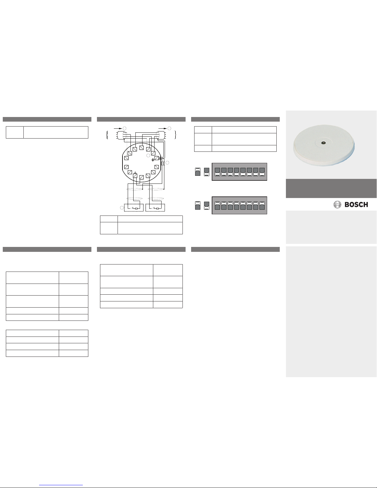
4 Internal EOL 12.1 kΩ resistors,
already onboard
2-wire connection (shielded)
– Use a 2-wire connection with a shielded
cable with a maximum length of 500 m and
an external EOL resistor (e.g. for lock contacts).
– Connect shielding only to the zone expander
module.
– Use one ferrite bead per shielding.
LSN
aLSN1
bLSN1
0V
+U
LSN
aLSN1
bLSN1
aLSN2
bLSN2
0V
I1
I2
I3
I4
II5
I6
II1
II2
II3
II4
II6
RE1
RE2
PL1
PL2
RE1
RE2
I5
I7
+U
aLSN2
bLSN2
0V
+U
II7
1
2
2
R
R
3
4
Element Description
1 Terminal for fed-through voltage sup-
ply
2 LSN connection
3 Ferrite bead (not part of the delivery);
approved: Wuerth # 74270017
4 2-wire connections, e.g. lock contacts
DIP switch settings for LSN improved mode
O
1 2 3 4 5
6
D I P
N
7 8
On O
DIP switch settings for LSN classic mode
O
1 2 3 4 5
6
D I P
N
7 8
On O
Technical data
Electrical
Minimum operating voltage in
VDC
10
Maximum operating voltage in
VDC
33
Maximum current consumption in mA
0.6
Number of primary lines 2
Terminal resistance in KΩ 12.1
Mechanical
Dimension in cm (Ø x D) 7.6 x 2.5
Housing material ABS
Color RAL 9002
Weight in g 54 g
Environmental
Minimum operating temperature in °C
0
Maximum operating temperature in °C
50
Protection class IP40
Security level IK04
Environmental class II
9 | 10 | 11 |
12 | 13 | 14 |
ISP-EM55FM-120 LSN 2 Zone Expander
Module, Recessed Mounting
en Quick Installation Guide
Bosch Sicherheitssysteme GmbH
Robert-Bosch-Ring 5
85630 Grasbrunn
Germany
www.boschsecurity.com
© Bosch Sicherheitssysteme GmbH, 2016
| 2016.08 | 10 | F.01U.318.467
 Loading...