

Bosch ISN-SM-50 Installation Manual
008738_b_−−_−− page 1
Papiergrösse = 360 x 270mm
3
/8” (10mm) Dia.
2
3
r=
4
/
4
1
F
12
GMX−P0
18
Installation manual 008738_b_--_-Edition 09.2005
Supersedes 008738_a_--_-A5Q00010255
ISN−SM−50
Seismic detector
Körperschallmelder
Détecteur sismique
Rivelatore sismico
Detector sísmico
Seismische detector
Relay shown in energised (non-alarm) condition
Relais in aufgezogenem Zustand (kein Alarm) gezeichnet
Le relais est dessinée à l’état attiré (pas d’alarme)
Il relè è rappresentato in stato eccitato (nessun allarme)
El relé ha sido dibujado en estado excitado (sin alarma)
*
Relais in opgetrokken toestand (geen alarm) getekend
1918
17
151413
GMX−W0
Raggio d’azione
Rayon d’action
Wirkradius
Operating radius
Radio de actuación
r =
Aanspreekstraal
Coverage area
Wirkbereich
Domaine d’efficacité
Campo d’azione
Campo de actuación
F =
Aanspreekgebied
16
21
1247
Test input
0V
DC 8...16V
Alarm relay
0V
14 15
*
<45R
10 11
spare
Remote
+5V
Tamper
30V
spare
9
4
76
5
8
1110
1 detector
1 Melder
1 détecteur
1 rivelatore
1 detector
1 detektor
2 detectors
2 Melder
2 détecteurs
2 rivelatori
2 detectores
2 detektoren
Solid metal cases
Solide Stahlschränke
Armoires en acier massif
Casse di metallo solido
Cofre de metal macizo
Solide stale kasten
r
r
r
r
r
X2½” (60mm)
r = 13ft. (4m)
¼” (6mm)
M4
1/8” (32mm) Dia.
at least 2” (50mm)
3
/8” (9mm) Dia.
12”
(300mm)
12”
(300mm)
GMXB0
7 3/32”
(180mm)
3 1/4” (80mm)
Option
GMXD7
TEST POINT
SW1, SW2
GMXS1
GMXD7 GMSW7
20
LED
008738_b_−−_−− page 2
Papiergrösse = 360 x 270mm
Seismic detector ISN−SM−50
Installation
Application
The ISN−SM−50 is a seismic detector with new detection and parameterization features.
The detection is improved by the patented disturbance filter and new clock filter.
The detector may be used together with ultrasonic de-
tectors.
The seismic detector ISN−SM−50 provides reliable protection for
− safes
− strongroom walls
− strongroom doors
− automatic cash dispensers
− vending machines
− ticket machines
against attack with explosives and break-in attempts
with any of the known tools, such as diamond-head
drills, hydraulic pressure tools, oxygen lances and attack using explosives.
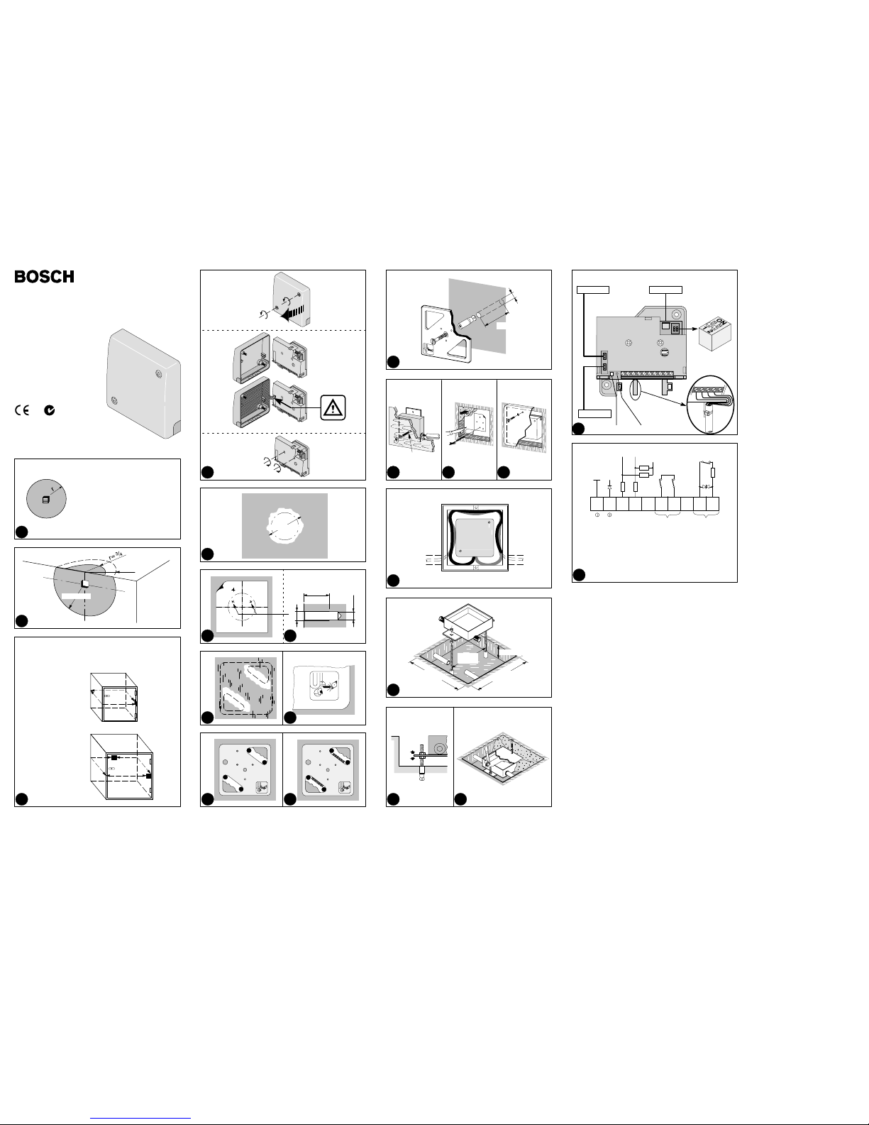
Coverage area fig. 1 + 2
The coverage area is highly dependent on the material
of the object to be monitored:
− Operating radius on steel: «r» = 6ft. 8” (2m)
− Operating radius on reinforced concrete: «r» = 13ft.
(4m)
The coverage area of the detector on strongroom
walls may also extend to part of the ceiling, floor, or
over corners if an homogeneous connection exists. In
such cases the operating radius is reduced to ¾ of the
range setting (fig. 2).
Joints between two materials always damp the struc-
ture-borne noise transmission. One detector on the
door and one on the body must always be installed.
This also applies to entrance doors of strongrooms.
Surveillance of metal cases fig. 3
The coverage area is designated as the surface of a mechanical obstacle which is monitored by a detector. The
coverage area is highly dependent on the material of the
object to be monitored. Practical experience has shown
that the operating radius for steel is 6ft. 8” (2m)
Note: Joints between two materials always damp the
structure-borne noise transmission, therefor not recommended on standard multilayer safes.
Installation
Opening the detector fig. 4
Unscrew the captive screws and lift off the metal cover
carefully.
− The seismic sensor is now exposed.
Fastening the detector fig. 4
Use only the two pre-assembled M4 cross-head screws
provided in order to fix the detector.
Direct mounting on steel fig. 5 to 7
The detector can be installed directly on steel plates
with a smooth surface. Ensure that any residual paint
between the steel surface and the seismic sensor is
completely removed and the mounting surface is level
to within 1/
128
” (0.1mm). If this is not possible, use
mounting plate GMX−P0.
1. Remove residual paint from sensor installation site
(fig. 5).
2. Stick on drilling template and centerpunch drill holes
(fig. 6).
3. Drill only the two marked holes of 1/8” (3.2mm) dia.
and tap M4 thread at least 1/4” (6mm) deep (fig. 7).
Deburr threaded holes.
4. Mount detector.
Do not use silicon grease between sensor and object!
Indirect installation with mounting plate GMX−P0
fig. 8 to 11
In the case of uneven or hardened steel plates, weld on
mounting plate GMX−P0.
1. Remove residual paint from the welding area (fig. 8).
2. Weld mounting plate in four fixing points. Ensure correct positioning (fig. 10).
ü The welding symbol must be visible on the front of
the mounting plate (fig. 9).
3. Weld along surfaces indicated. Tap off slag and remove weld spatter from the plate surface (fig. 11).
4. Mount detector.
Do not use silicon grease between sensor and
mounting plate!
Installation on concrete using mounting plate
GMX−P0 fig. 12
Never install the detector directly on a bare or plastered
concrete surface, since bending forces may cause
damage to the seismic sensor. Plaster of less than
10mm need not be removed.
1. Drill center hole 3/8” (10mm) dia. at least 2” (50mm)
deep using a sintered carbide bit (fig. 12).
2. Insert metal plug into drilled hole flush with the concrete surface. Use metal plugs only!
3. Ensure that the mounting plate is correctly positioned. Press the mounting plate onto surface, knock
in screw with plug and tighten well. The plate should
no longer be capable of rotation.
4. Mount detector.
Do not use silicon grease between sensor and
mounting plate!
Recessed mounting with wall recess plate
GMX−W0 fig. 13 to 15
1. Drill 3/8” (9mm) dia. hole in wooden concrete mould.
2. Fasten the wall recess set by inserting threaded bolt
and tightening wing nut (fig. 13).
3. Push the installation conduit through the polystyrene
block.
4. After removing mould, unscrew threaded bolt.
Scrape out polystyrene and cut off conduit flush (fig.
14).
5. Mount detector.
6. Mount cover plate (fig. 15).
Cable feed in wall box and floor box fig. 16
Insert cable with reserve loop into the box. Ensure appropriate cable length when drawing the cable in.
Installation in floor box GMX−B0 fig. 17 to 19
To install the floor box GMX−B0, a recess with a base
area of at least 12” x 12” (300x 300mm) and a depth of
3¼” (80mm) is required (fig. 17). Use a polystyrene
block to keep this recess open when pouring in the wet
concrete.
Two threaded bolts M6x4” (M6x100mm) screwed into
metal plugs provide the acoustic connection between
the detector and the concrete floor.
1. Level floor box using the nuts on the two threaded
bolts. Fix position finally by tightening the lock nuts
(fig. 18).
2. Feed installation conduits through sealing sleeves.
Fill recess with wet cement.
3. Pull cable through and thoroughly seal the entry
openings for protection against moisture (fig. 19).
4. Mount the detector.
5. Fit cover plate. Cut out wood or carpet floor covering
and stick to cover plate.
Installation accessories
GMX−D7 Anti-drilling foil fig. 4
A special anti-drilling foil is available for fitting into the
detector cover as an additional protection against tampering, if required. For installation refer to the separate
mounting sheet delivered with the GMX−D7.
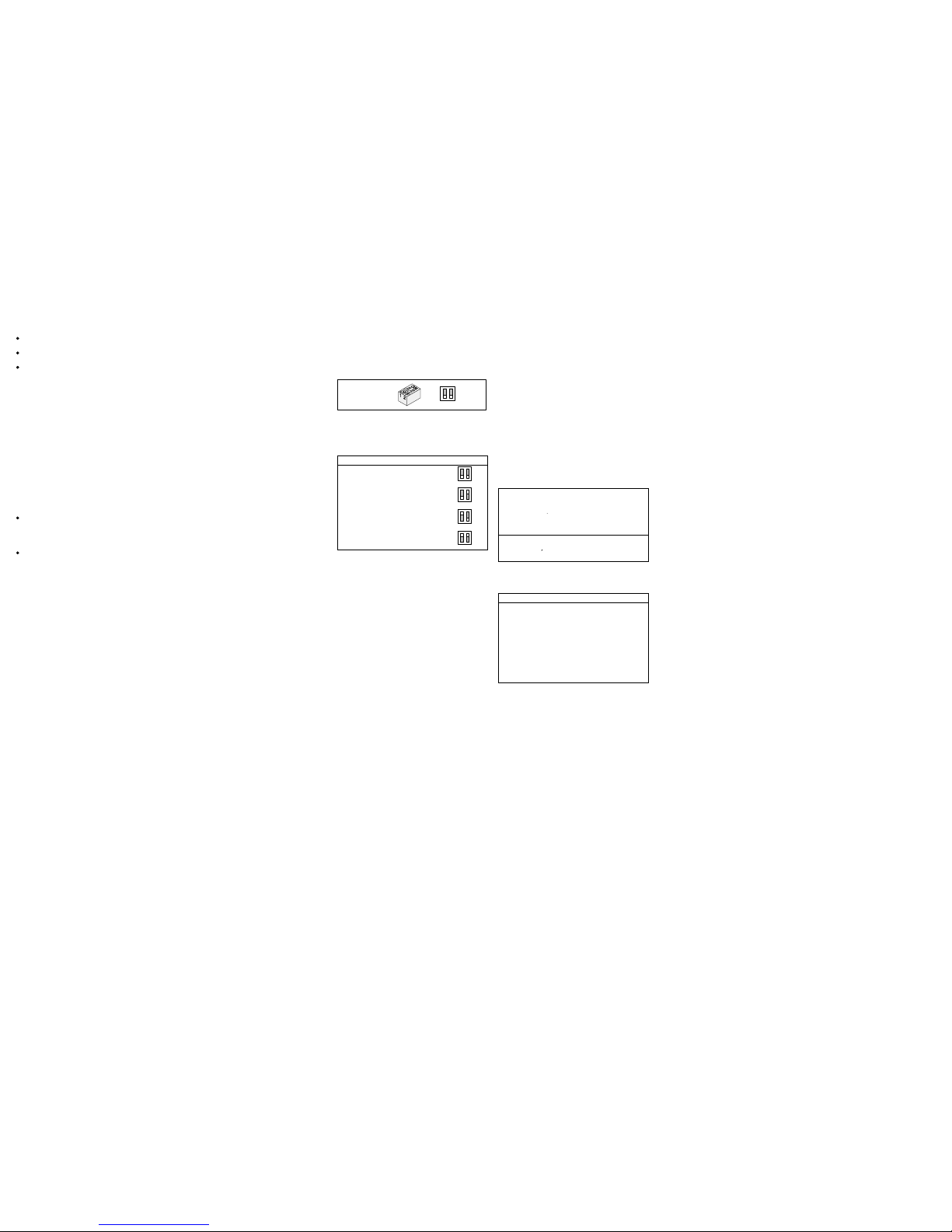
Programming
After the detector housing has been opened, use the
switches to select the respective settings.
SW1, SW2
12
ON
OFF
Application settings, SW1 and SW2
Select the sensitivity setting to suit the application, the
material and the object with the associated interference.
Important: During commissioning, be sure to check for
function-related noise (see ”Commissioning”).
Settings on the detector
Steel 6ft.8” (2.0m)
12
ON
OFF
Steel 4ft. 9” (1.5m)
12
ON
OFF
Concrete 13ft. ( 4.0m)
12
ON
OFF
User Mode, with SMS−W7 SensTool
12
ON
OFF
Remote controlled sensitivity reduction fig. 21
An additional feature of this detector is a sensitivity reduction input at terminal 7 ”Remote” which can be remotely activated if required.
Using a LOW signal (0V), the detector is reduced to
about 1/8 of the sensitivity setting for as long as there is
heavy functional noise by means of a touch-sensitive
switch on the opening device during operation of daynight deposit.
ü Open control input is HIGH (internal pull-up resistor).
Test input fig. 21
The test input terminal 4 is used for the functional testing
of the seismic detector together with the GMX−S1.
With TEST ON the functional test is run once and a pos-
itive test result is output to the alarm relay.
ü Open control input is HIGH (internal pull-up resistor).
LED
During commissioning or when changing operating
mode the red LED flashes until the detector is ready for
operation.
Lights on alarm condition for approx. 2.5s.
Commissioning
If the GMX−S1 test transmitter is to be used, it must be
connected before power is switched on.
Procedure:
1. Switch on voltage − wait 1 minute − the detector is
ready for operation.
2. Functional check: Simulate an attack signal in the supervised area, for example scratch lightly with a
screwdriver or test signal GMX−S1 − the detector
should trigger an alarm.
3. Interference checks: Connect an universal measuring instrument (impedance ≥20kΩ) between terminal
1 (0V) and “TEST POINT” for integrator signal:
− quiescent level 0V. . . . . . . . . . . . . . . . . . . . .
− integration start 1.0V. . . . . . . . . . . . . . . . . . . .
− alarm threshold (without load) 3.0V. . . .
4. Carefully close the cover, tightening the housing
screw.
SensTool SMS−W7
The SensTool software allows operating parameters to
be set individually. In addition, current information such
as integrator signals can be viewed and stored.
The following additional settings are possible, depending on the application, material and object, with corresponding interferences:
3ft.4” (1.0m)
Steel
4ft.9” (1.5m)
Detector sensitivity
6ft.8” (2.0m)
y
8ft.2” (2.5m)
Concrete
13ft. (4.0m)
low
Shock sensitivity
mid
y
high
Recommended sensitivity settings
The following approximate values can be used as reference values for the setting of the seismic detector:
Application Sensitivity Shock
Ticket machine
with heavy functional related noises,
exposed location
Steel
3ft.4” (1.0m)
low
Autom. cash dispenser, Day/night
deposit, Safe door
with heavy functional related noises
Steel
4ft.9” (1.5m)
mid
Armored safe, Strongroom door
with functional related noises
Steel
6ft.8” (2.0m)
mid
Strongroom, Modular vault
with light interferences
Concrete
8ft.2” (2.5m)
high
Strongroom, Modular vault
with minimum interferences
Concrete
13ft. (4.0m)
high
Maintenance
Test detectors regularly (at least once a year) for operation and firm mounting.
Approvals
CE conforms. . . . . . . . . . . . . . . . . . . . . . . . . . . . . . . . . . . . . . . . . . . .
UL applied for. . . . . . . . . . . . . . . . . . . . . . . . . . . . . . . . . . . . . . . . . . .
Any national approval requirements relating to the application of the product must be complied with.
Technical data
Detector
Supply voltage (nom. 12VDC) 8.0...16.0VDC. . . . . . . . . . . . . . . .
Current consumption (at 12DC, quiescent) typ. 3mA. . . . . . . . .
− alarm condition 5mA. . . . . . . . . . . . . . . . . . . . . . . . . . . . . . . . . . . . .
Alarm output, terminals 14+15:
Semiconductor relay opens on alarm and/or low voltage
. . . . .
− contact load 30VDC/100mA, ohmic load. . . . . . . . . . . . . . . . . . .
− series resistance ≤45Ω. . . . . . . . . . . . . . . . . . . . . . . . . . . . . . . . . .
Alarm holding time 2.5s. . . . . . . . . . . . . . . . . . . . . . . . . . . . . . . . . . . .
Sabotage surveillance:
Tamper, terminals 10+11:
− microswitches for cover + body opens on tamper
. . . . . . . . .
− contact load 30VDC/100mA. . . . . . . . . . . . . . . . . . . . . . . . . . . . . . .
Supply voltage <7V...8V ⇒ alarm. . . . . . . . . . . . . . . . . . . . . . . . . . .
Anti-drilling foil in cover tamper ⇒ alarm. . . . . . . . . . . . . . . . . . . .
Sensitivity reduction input, terminal 7:
− for reduction LOW ≤1.5V / HIGH ≥3.5V
. . . . . . . . . . . . . . . . . . .
− reduction to 1/8 of the actual setting. . . . . . . . . . . . . . . . . . . . . .
Sensitivity, adjustable in 3 fixed levels +. . . . . . . . . . . . . . . . . . . . .
SW programmable with SensTool
Functional test input, terminal 4:
− for test LOW ≤1.5V / HIGH ≥3.5V
. . . . . . . . . . . . . . . . . . . . . . . .
− with GMX−S1, test duration ≤3s. . . . . . . . . . . . . . . . . . . . . . . . . .
Measuring output, TEST POINT analogue integration signal.
− quiescent level 0V. . . . . . . . . . . . . . . . . . . . . . . . . . . . . . . . . . . . . . .
− integration start 1,0V. . . . . . . . . . . . . . . . . . . . . . . . . . . . . . . . . . . . .
− alarm treshold (without load) 3,0V. . . . . . . . . . . . . . . . . . . . . . . .
Operating radius on steel r = 6ft. 8” (2.0m). . . . . . . . . . . . . . . . .
Coverage area on steel 43sq.ft. (13m2). . . . . . . . . . . . . . . . . . . . .
Ambient conditions:
− operating temperature −40°F to +158°F (−40°C to +70°C)
− storage temperature −58°F to +158°F (−50°C to +70°C)
. .
− humidity, DIN class F <95%. . . . . . . . . . . . . . . . . . . . . . . . . . . . . .
− housing protection category (EN60529, EN50102) IP435. .
− VdS environmental class III. . . . . . . . . . . . . . . . . . . . . . . . . . . . . . .
− insensitive to RD interferences
0.01...2GHz (IEC 801-3) 30V/m
. . . . . . . . . . . . . . . . . . . . . . . . . .
Accessories
GMX−W0 Wall recess set with cover
− housing protection category IEC IP51
. . . . . . . . . . . . . . . . . . . .
− max. carrying capacity of cover 25kg. . . . . . . . . . . . . . . . . . . . .
GMX−B0 Floor box
− housing protection category IEC IP51
. . . . . . . . . . . . . . . . . . . .
− max. carrying capacity of cover plate 1000kg. . . . . . . . . . . . .
GMXW−G0 Watertight housing
− housing protection category IEC IP65
. . . . . . . . . . . . . . . . . . . .
− max. carrying capacity of cover 1000kg. . . . . . . . . . . . . . . . . .
Details for ordering
Elements supplied with detector
1 Seismic detector
1 Mounting instructions
1 Mounting template
3 Cable straps
Seismic detector ISN−SM−50
. . . . . . . . . . . . . . . . . . . . . . . . . . . . .
Mounting plate ISN−GMX−P0. . . . . . . . . . . . . . . . . . . . . . . . . . . . . . .
Wall recess set w/cover ISN−GMX−W0. . . . . . . . . . . . . . . . . . . . .
Floor box ISN−GMX−B0. . . . . . . . . . . . . . . . . . . . . . . . . . . . . . . . . . .
Watertight housing ISN−GMXW−G0. . . . . . . . . . . . . . . . . . . . . . . .
Swivel plate ISN−GMX−P3S. . . . . . . . . . . . . . . . . . . . . . . . . . . . . . .
Test transmitter ISN−GMX−S1. . . . . . . . . . . . . . . . . . . . . . . . . . . . . .
SensTool, interface and software ISN−SMS−W7. . . . . . . . . . . .
Anti-drilling foil (10 pcs) ISN−GMX−D7. . . . . . . . . . . . . . . . . .
Fixing plate ISN−GMA−S6. . . . . . . . . . . . . . . . . . . . . . . . . . . .
Spacer, 2mm ISN−GMX−P3S2. . . . . . . . . . . . . . . . . . . . . . . . .
Spacer, 4mm ISN−GMX−P3S4. . . . . . . . . . . . . . . . . . . . . . . . .
Swivel plate ISN−GMX−PZ
. . . . . . . . . . . . . . . . . . . . . . . . . . . . . . . .
008738_b_−−_−− page 3
Papiergrösse = 360 x 270mm
Körperschallmelder ISN−SM−50
Montage
Anwendung
Der ISN−SM−50 ist ein Körperschallmelder mit neuen
Detektions- und Parameterisierungseigenschaften.
Die Detektion ist verbessert durch das patentierte
Störsignalfilter und das neue Clock-Filter.
Der Melder kann zusammen mit Ultraschallmeldern
eingesetzt werden.
Der Körperschallmelder ISN−SM−50 eignet sich für das
Überwachen von
− Kassenschränken
− Tresormauern
− Tresorraumtüren
− Geldausgabeautomaten
− Verkaufsautomaten
− Fahrscheinautomaten
auf Angriffe mit allen heute bekannten Einbruchwerkzeugen wie Diamantkronenbohrern, hydraulischen
Presswerkzeugen, Sauerstofflanzen und ebenso auf
Angriffe mit Sprengstoffen.
Wirkbereich Fig. 1 + 2
Der Wirkbereich ist stark vom Material des zu überwachenden Objektes abhängig:
− Wirkradius auf Stahl: «r» = 2m
− Wirkradius auf eisenarmierten Beton: «r» = 4m
Die Wirkbereiche von Meldern an Tresorwänden kön-
nen sich auch auf einen Teil der Decke oder des Bo-
dens erstrecken, wenn die Armierungseisen gut mit-
einander verbunden sind. In solchen Fällen reduziert
sich der Wirkradius auf ¾ des eingestellten Bereichs
(Fig. 2).
Fugen zwischen zwei Materialien stellen immer eine
Dämpfung für die Körperschallübertragung dar. Da-
her grundsätzlich sowohl Türe wie Schrank mit Mel-
dern ausrüsten. Dies gilt auch für Eingangstüren von
Tresorräumen.
Überwachen von Stahlschränken Fig. 3
Als Wirkbereich wird die Oberfläche eines von einem
Melder überwachten Gegenstandes bezeichnet. Der
Wirkbereich ist in hohem Masse vom Material des zu
überwachenden Objektes abhängig. Nach der Erfahrung in der Praxis gilt für Stahl ein Wirkradius «r» von
2,0m.
Achtung: Fugen zwischen zwei Materialien dämpfen in
jedem Fall die Übertragung des Körperschalls, daher
für Multilayer-Safes nicht geeignet.
Installation
Öffnen des Melders Fig. 4
Die unverlierbaren vorderen Schrauben lösen und den
Metalldeckel vorsichtig abheben.
− Der Körperschallsensor liegt nun frei.
Befestigen des Melders Fig. 4
Zur Befestigung des Melders die beiden vormontierten
Kreuzschlitzschrauben M4 verwenden.
Direkte Montage auf Stahl Fig. 5 − 7
Auf Stahlplatten mit glatter Oberfläche kann der Melder direkt montiert werden. Dabei beachten, dass jegliche Farbresten zwisc hen Stahloberfläche und Körpersc hall-Sensor restlos entfernt sind und die Mont ageoberfläche eine
Ebenheit besser 0,1mm aufweis t. Ist dies nicht möglich,
die Befestigungsplatte GMX −P0 verwenden.
1. Von der Montagestelle für den Sensor alle Farbreste
entfernen (Fig. 5).
2. Die Montageschablone aufkleben und die beiden
Bohrstellen ankörnen (Fig. 6).
3. Bohren Sie nur die zwei markierten Löcher mit einem
Durchmesser von 3,2mm, schneiden Sie das
M4-Gewinde mindestens 6mm tief (Fig. 7). Die Gewindelöcher entgraten.
4. Montieren Sie den Melder.
Zwischen dem Sensor und dem Objekt darf kein Silikonfett aufgetragen werden!
Indirekte Montage mit Befestigungsplatte GMX−
P0
Fig. 8 − 11
Bei unebenen und gehärteten Stahlplatten die Befestigungsplatte GMX−P0 aufschweißen.
1. Von der Schweißstelle die gesamte Farbe entfernen
(Fig. 8).
2. Die Befestigungsplatte an vier Punkten anheften.
Achten Sie auf die richtige Positionierung (Fig. 10).
ü Das Schweißsymbol muss auf der Vorderseite der
Befestigungsplatte zu sehen sein (Fig. 9).
3. Die Schweißnähte entlang der angegebenen Stellen
anbringen. Die S chlacke abklopfen und Sc hweißspritzer von der Plattenoberfläche entfernen (Fig. 11).
4. Montieren Sie den Melder.
Zwischen dem Sensor und der Befestigungsplatte
darf kein Silikonfett aufgetragen werden!
Montage auf Beton mit Befestigungsplatte GMX−
P0 Fig. 12
Der Melder darf nicht direkt auf eine rohe oder verputzte
Betonoberfläche montiert werden, da durch Verbiegungskräfte der Körperschallsensor beschädigt werden könnte. Verputz von weniger als 10mm muss nicht
entfernt werden.
1. Mit einem Hartmetallbohrer ein Mittelloch mit einem
Durchmesser von 10mm und einer Tiefe von mindestens 50mm bohren (Fig. 12).
2. Einen Metalldübel bündig zur Betonoberfläche in das
gebohrte Loch einsetzen. Es dürfen nur Metalldübel
verwendet werden!
3. Stellen Sie sicher, dass die Befestigungsplatte richtig
positioniert ist. Drücken Sie die Befestigungsplatte
auf die Oberfläche, setzen Sie die Schraube ein, und
ziehen Sie sie fest an. Die Platte darf nicht mehr verdreht werden können.
4. Montieren Sie den Melder.
Zwischen dem Sensor und der Befestigungsplatte
darf kein Silikonfett aufgetragen werden!
Unterputzmontage mit Wandeinbau-Set GMX−W0
Fig. 13 − 15
1. In die Holzschalung ein Loch mit einem Durchmesser
von 9mm bohren.
2. Die Wandeinbauplatte befestigen, indem die Gewindestange eingesetzt und die Flügelmutter festgezogen wird (Fig. 13).
3. Das Installationsrohr durch den Schaumstoffklotz
schieben.
4. Nach dem Entfernen der Schalung die Gewindestange herausschrauben. Den Schaumstoff herauskratzen und das Installationsrohr bündig abschneiden (Fig. 14).
5. Montieren Sie den Melder.
6. Montieren Sie die Abdeckplatte (Fig. 15).
Kabelführung in Wand- und Bodendose Fig. 16
Das Kabel muss mit einer Reserveschlaufe in die Dose
eingelegt werden. Beim Einziehen des Kabels auf eine
ausreichende Kabellänge achten.
Montage in Bodendose GMX−B0 Fig. 17 − 19
Für den Einbau der Bodendose GMX−B0 ist eine Aussparung mit einer Grundfläche von mindestens 300mm
x 300mm und einer Tiefe von 80mm erforderlich (Fig.
17). Diese Aussparung mit einem Schaumstoffklotz
beim Ausgießen des Bodens freihalten.
Zwei in Metalldübel geschraubte Gewindebolzen
M6x100mm stellen die akustische Verbindung zwischen dem Melder und dem Betonboden her.
1. Die Bodendose mit den Muttern an den beiden Gewindebolzen nivellieren. Zum Fixieren anschliessend die Kontermuttern festziehen (Fig. 18).
2. Die Installationsrohre durch die Dichtungsmuffen
einführen. Die Aussparung mit dünnflüssigem Beton
ausgießen.
3. Das Kabel einziehen. Die Einführungsöffnungen
müssen zum Schutz vor Feuchtigkeit sorgfältig abgedichtet werden (Fig. 19).
4. Montieren Sie den Melder.
5. Die Abdeckplatte anbringen. Holz- oder Teppichbeläge ausschneiden und auf die Abdeckplatte kleben.
Montagezubehör
Bohrschutzfolie GMX−D7 Fig. 4
Um den Melder zusätzlich vor Sabotage zu schützen,
kann eine spezielle Bohrschutzfolie in den Melderdeckel eingeklebt werden. Montage siehe separate
Anweisung der Bohrschutzfolie beiliegend.
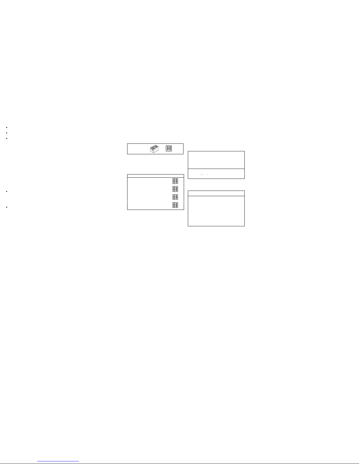
Programmierung
Nach dem Öffnen des Meldergehäuses entsprechende
Einstellungen mit den Schaltern wählen.
SW1, SW2
12
ON
OFF
Applikationseinstellungen, SW1 und SW2
Je nach Anwendung und Material wird die entsprechende Einstellung gewählt.
Wichtig: Bei Inbetriebnahme immer auf funktionsbedingte Geräusche überprüfen (siehe ”Inbetriebnahme”).
Einstellungen am Melder
Stahl 2,0m
12
ON
OFF
Stahl 1,5m
12
ON
OFF
Beton 4,0m
12
ON
OFF
User Mode, mit SMS−W7 SensTool
12
ON
OFF
Fernbedienbare Reduktion der Empfindlichkeit
Fig. 21
Zusätzlich verfügt dieser Melder auf Klemme 7 ”Remote” über einen Empfindlichkeitsreduktions-Eingang,
welcher bei Bedarf extern angesteuert werden kann.
Der Melder wird mit einem LOW-Signal auf etwa 1/8 der
eingestellten Empfindlichkeit reduziert, solange funktionsbedingte starke Geräusche vorliegen, z.B. mit Kontaktschalter an Einwurfvorrichtung während der Bedienung von Tag-Nacht-Tresoranlagen.
ü Offener Steuereingang ist HIGH (interner «Pullup»-Widerstand).
Testeingang Fig. 21
Der Testeingang Klemme 4 ”Test” dient dem Funktionstest des Körperschallmelders zusammen mit dem Prüfsender GMX−S1.
Bei TEST EIN wird der Funktionstest einmal durchgeführt und ein positives Testresultat auf das Alarmrelais
ausgegeben (identisch mit Alarm).
ü Offener Steuereingang ist HIGH (interner «Pullup»-Widerstand).
LED-Anzeige
Bei der Inbetriebnahme oder beim Umschalten der Applikationseinstellung blinkt die rote LED bis die Initialisierung abgeschlossen ist.
Bei Alarm leuchtet die LED für ca. 2,5s.
Inbetriebnahme
Wenn der Prüfsender GMX−S1 verwendet wird, muss
er bevor die Spannung zugeschaltet wird angeschlossen werden.
Vorgehen:
1. Spannung zuschalten − 1 Min. warten − Melder ist betriebsbereit.
2. Funktionsprüfung: Einbruchsignal im überwachten
Wirkbereich simulieren, z.B. mit Schraubenzieher
kratzen oder Prüfsignal GMX−S1 − Melder löst Alarm
aus.
3. Überprüfen von Störeinflüssen:
Messinstrument (Ri ≥20kΩ) an Klemme 1 (0V) und
”TEST POINT” für analoges Integrationssignal:
− Ruhepegel 0V. . . . . . . . . . . . . . . . . . . . . . . . .
− Integrationsstart 1,0V. . . . . . . . . . . . . . . . .
− Alarmschwelle (unbelastet) 3,0V. . . . .
4. Deckel vorsichtig schließen, die Gehäuseschraube
festziehen.
SensTool SMS−W7
Die SensTool-Software ermöglicht Betriebsparameter
individuell einzustellen. Auch können aktuelle Informationen wie z.B. das Integrationssignal angesehen und
gespeichert werden.
Folgende zusätzliche Einstellungen können je nach Anwendung, Material und Objekt mit entsprechenden
Störeinflüssen vorgenommen werden:
1,0m
Stahl
1,5m
Melder-Empfindlichkeit
2,0m
p
2,5m
Beton
4,0m
niedrig
Erschütterungs-Empfindlichkeit
mittel
gp
hoch
Empfohlene Empfindlichkeits-Einstellungen
Folgende Angaben können als Richtwerte für die Einstellung des Körperschallmelders beigezogen werden:
Anwendung Empfind-
lichkeit
Erschütterungen
Billetautomat
starke funktionsbedingte Geräusche, exponierter Standort
Stahl
1,0m
niedrig
Bankomat, Tag/Nacht/-Tresoranlage,
Geldschranktüre
starke funktionsbedingte Geräusche
Stahl
1,5m
mittel
Panzer-Geldschrank, Tresorraumtüre
funktionsbedingte Geräusche
Stahl
2,0m
mittel
Tresorraum, Elemente-Tresor
leichte Störeinflüsse
Beton
2,5m
hoch
Tresorraum, Elemente-Tresor
minimale Störeinflüsse
Beton
4,0m
hoch
Unterhalt
Melder regelmäßig (min. 1mal pro Jahr) auf Funktion
und Befestigung prüfen.
Zulassungen
CE konform. . . . . . . . . . . . . . . . . . . . . . . . . . . . . . . . . . . . . . . . . . . . . .
UL eingereicht. . . . . . . . . . . . . . . . . . . . . . . . . . . . . . . . . . . . . . . . . .
Nationale Zulassungsbedingungen, welche die Anwendung des Produktes betreffen, sind einzuhalten.
Technische Daten
Melder
Speisespannung (nom. 12V−) 8,0...16,0V−. . . . . . . . . . . . . . . . . .
Stromaufnahme (bei 12V−, Ruhe) typ. 3mA. . . . . . . . . . . . . . . .
− Alarmzustand 5mA. . . . . . . . . . . . . . . . . . . . . . . . . . . . . . . . . . . . .
Alarmausgang, Klemmen 14+15:
− Halbleiter-Relais öffnet bei Alarm + Unterspannung
. . . . . . .
− Kontaktbelastung 30V−/100mA, ohmsche Last. . . . . . . . . . . .
− Seriewiderstand ≤45Ω. . . . . . . . . . . . . . . . . . . . . . . . . . . . . . . . . . .
− Alarmhaltezeit 2,5s. . . . . . . . . . . . . . . . . . . . . . . . . . . . . . . . . . . . . .
Sabotageüberwachung:
Tamper, Klemmen 10+11
− Mikroschalter, Deckel + Boden öffnet bei Sabotage
. . . . . . .
− Kontaktbelastung 30V−/100mA. . . . . . . . . . . . . . . . . . . . . . . . . . .
Spannungsüberwachung <7V ⇒ Alarm. . . . . . . . . . . . . . . . . . . .
Bohrschutzfolie im Deckel Sabotage ⇒ Alarm. . . . . . . . . . . . .
Empfindlichkeitsreduktions-Eingang, Klemme 7:
− für Reduktion LOW ≤1,5V / HIGH ≥3,5V
. . . . . . . . . . . . . . . . . .
− Reduktion auf 1/8 der aktuellen Einstellung. . . . . . . . . . . . . . .
Empfindlichkeit einstellbar in 3 festen Stufen +. . . . . . . . . . . . . .
SW-programmierbar mit SensTool
Test-Eingang, Klemme 4:
− für Test LOW ≤1,5V / HIGH ≥3,5V
. . . . . . . . . . . . . . . . . . . . . . . .
− mit GMX−S1, Testdauer ≤3s. . . . . . . . . . . . . . . . . . . . . . . . . . . . .
Messausgang, TEST POINT analoges Integrationssignal. . . .
− Ruhepegel 0V. . . . . . . . . . . . . . . . . . . . . . . . . . . . . . . . . . . . . . . . . . .
− Integrationsstart 1,0V. . . . . . . . . . . . . . . . . . . . . . . . . . . . . . . . . . . .
− Alarmschwelle (unbelastet) 3,0V. . . . . . . . . . . . . . . . . . . . . . . . .
Wirkradius auf Stahl r = 2m. . . . . . . . . . . . . . . . . . . . . . . . . . . . . . . .
Wirkbereich auf Stahl 13m
2
. . . . . . . . . . . . . . . . . . . . . . . . . . . . . . . .
Umweltbedingungen:
− Betriebstemperatur −40°...+70°C
. . . . . . . . . . . . . . . . . . . . . . . .
− Lagertemperatur −50°...+70°C. . . . . . . . . . . . . . . . . . . . . . . . . . .
− Luftfeuchtigkeit, DIN Klasse F <95%. . . . . . . . . . . . . . . . . . . . . .
− Gehäuseschutzart (EN60529, EN50102) IP435. . . . . . . . . . .
− VdS-Umweltklasse III. . . . . . . . . . . . . . . . . . . . . . . . . . . . . . . . . . . .
− EMV-Festigkeit 0,01...2GHz (IEC801-3) 30V/m. . . . . . . . . . .
Zubehör
GMX−W0 Wand-Unterputz-Set mit Abdeckung
− Gehäuseschutzart nach IEC IP51
. . . . . . . . . . . . . . . . . . . . . . . .
− Maximale Tragkraft der Abdeckung 25kg. . . . . . . . . . . . . . . . .
GMX−B0 Bodendose
− Gehäuseschutzart nach IEC IP51
. . . . . . . . . . . . . . . . . . . . . . . .
− Maximale Tragkraft der Deckelplatte 1000kg. . . . . . . . . . . . .
GMXW−G0 Wasserdichtes Gehäuse
− Gehäuseschutzart nach IEC IP65
. . . . . . . . . . . . . . . . . . . . . . . .
− Maximale Tragkraft der Abdeckung 1000kg. . . . . . . . . . . . . .
Bestellangaben
Lieferumfang des Melders
1 Körperschallmelder
1 Montageanleitung
1 Montageschablone
3 Kabelbinder
Körperschallmelder ISN−SM−50
. . . . . . . . . . . . . . . . . . . . . . . . . .
Befestigungsplatte ISN−GMX−P0. . . . . . . . . . . . . . . . . . . . . . . . . . .
Wandeinbau-Set mit Abdeckung ISN−GMX−W0. . . . . . . . . . . .
Bodendose ISN−GMX−B0. . . . . . . . . . . . . . . . . . . . . . . . . . . . . . . . . .
Wasserdichtes Gehäuse ISN−GMXW−G0. . . . . . . . . . . . . . . . . .
Schwenkplatte für Schlossabdeckung ISN−GMX−P3S. . . . . .
Prüfsender ISN−GMX−S1. . . . . . . . . . . . . . . . . . . . . . . . . . . . . . . . . .
SensTool, Schnittstelle + Software ISN−SMS−W7. . . . . . . . . .
Bohrschutzfolie (10 Stück) ISN−GMX−D7. . . . . . . . . . . . . . . . . .
Befestigungsplatte ISN−GMA−S6. . . . . . . . . . . . . . . . . . . . . .
Distanzscheibe, 2mm ISN−GMX−P3S2. . . . . . . . . . . . . . . . . .
Distanzscheibe, 4mm ISN−GMX−P3S4. . . . . . . . . . . . . . . . . .
Schwenkplatte ISN−GMX−PZ
. . . . . . . . . . . . . . . . . . . . . . . . . . . . . .
 Loading...