

Bosch ISN-SM-30, ISN-SM-80, ISN-SM-50, ISN-SM-90 Application Manual

ISN-SM-xx
Seismic Detectors and Accessories
Application Guide

Copyright
2
Copyright
Technical specifications and availability subject to change without notice.
© Copyright Bosch Security Systems 2016
We reserve all rights in this document and in the subject thereof. By acceptance of the document
the recipient acknowledges these rights and undertakes not to publish the document nor the subject thereof in full or in part, nor to make them available to any third party without our prior express
written authorization, nor to use it for any purpose other than for which it was delivered to him.
Edition: 04.2016
Document ID: I-200153-1
Bosch Security Systems Seismic Detectors Application Guide I-200153-1
04.2016

3
Table of contents
1 General information ........................................................................................... 5
1.1 Detector and accessory overview ........................................................................ 6
2 Applications ........................................................................................................ 7
2.1 Detector applications and attack profiles ............................................................. 7
2.2 Detector selection ................................................................................................. 8
2.3 Steel applications and accessory options ............................................................ 9
2.4 Concrete applications and ac c ess ory options ...................................................... 9
3 Installation - Detectors ..................................................................................... 10
3.1 Drill template....................................................................................................... 10
3.2 Installation methods ........................................................................................... 10
3.3 Detector installation onto flat steel surface ........................................................ 10
3.4 Detector installation on steel using the GMXP0 mounting plate ........................ 11
3.4.1 Weld fixing .......................................................................................... 11
3.4.2 Screw fixing ......................................................................................... 12
3.4.3 Glue Fixing .......................................................................................... 13
3.5 Indirect installation on concr ete .......................................................................... 14
4 Installation - Accessories ................................................................................ 17
4.1 GMXP0 mounting plate ...................................................................................... 17
4.2 GMXS1 internal test transmitter ......................................................................... 17
4.3 GMXS5 – External test transmitter ..................................................................... 19
4.4 GMXW0 wall mounting kit .................................................................................. 22
4.5 GMXB0 floor box ................................................................................................ 23
4.6 GMXP3 & GMXP3Z lock protection system ....................................................... 24
4.7 GMAS6 movable mounting kit ............................................................................ 24
4.8 GMXD7 ............................................................................................................... 26
4.9 GMSW7 SensTool software ............................................................................... 26
4.10 GMXC2 conduit connection cover ...................................................................... 27
4.11 GMXC4 seismic test tool .................................................................................... 27
5 Planning ............................................................................................................ 28
5.1 General Application ............................................................................................ 28
5.2 General Planning Guidelines.............................................................................. 28
5.3 Planning limitations ............................................................................................ 28
5.4 Installation guidelines ......................................................................................... 29
5.4.1 Detector Requirements ....................................................................... 29
5.4.2 System Requirements ......................................................................... 29
6 Design ................................................................................................................ 31
6.1 General Principles .............................................................................................. 31
6.1.1 Calculating the number of detectors required - Example 1 ................ 33
6.1.2 Calculating the number of detectors required - Example 2 ................ 34
6.1.3 Calculating the number of detectors required – Example 3 ................ 36
6.2 Modular vaults .................................................................................................... 37
Bosch Security Systems Seismic Detectors Application Guide I-200153-1
04.2016

4
6.2.1 Interlocking panels .............................................................................. 37
6.2.2 Panels with steel surrounds ................................................................ 38
6.3 Vault protection guidelines ................................................................................. 39
6.4 Night Deposit Box and ATM Applicat ions .......................................................... 42
6.4.1 Night deposit boxes ............................................................................ 42
6.4.2 ATM’s .................................................................................................. 43
6.4.3 General Design Guide for Night Safes & ATMs.................................. 43
6.4.3.1 Detector sensitivity .............................................................................. 44
6.5 Cabinet Protection .............................................................................................. 45
6.6 Document cabinet .............................................................................................. 45
6.7 Filing cabinet ...................................................................................................... 46
6.8 Gun cabinet ........................................................................................................ 46
7 Commissioning ................................................................................................ 47
7.1 Pre-commissioning checklist .............................................................................. 47
7.2 Commissioning & test options ............................................................................ 47
7.3 Staged commissioning ....................................................................................... 48
7.3.1 Staged commissioning procedure ...................................................... 48
8 SensTool ........................................................................................................... 50
8.1 SensTool GMXS7 ............................................................................................... 50
8.1.1 SensTool User Mode Settings (recommended).................................. 50
8.2 Setting up Senstool ............................................................................................ 50
8.3 Recording ambient noise levels ......................................................................... 51
8.4 Trouble Shooting ................................................................................................ 52
8.5 Using SensTool as a record of commissioning .................................................. 53
9 Interface to SPC Panel/System ....................................................................... 54
9.1 General Electrical Connections .......................................................................... 54
9.2 Testing the detectors .......................................................................................... 55
9.2.1 Manual Test ........................................................................................ 55
9.2.2 Automatic Test .................................................................................... 55
9.2.3 Automatic test when setting ................................................................ 56
9.3 Test and indication flow ...................................................................................... 57
9.4 User Interface ..................................................................................................... 57
10 Useful information ............................................................................................ 58
10.1 Cross-reference chart for country-specific approvals ........................................ 58
10.2 Cross reference chart for all related internal documentation ............................. 59
10.3 Cross reference chart for applicable, external related documents ..................... 61
10.4 Cross reference list of all part numbers ............................................................. 61
10.5 Graphic Index ..................................................................................................... 63
10.6 Table Index ......................................................................................................... 64
11 Appendix 1: Drill template ISN-SM-xx ............................................................ 65
12 Appendix 2: Drill Template GMXP3/Z ............................................................. 66
13 Appendix 3: Drill Template GMXS5 ................................................................ 67
Bosch Security Systems Seismic Detectors Application Guide I-200153-1
04.2016
General information
1
5
1 General information
The ISN-SM-xx range of seismic detectors operate at maximum efficiency on steel or connot be guaranteed.
The Bosch Security Systems ISN-SM-xx range of seismic detectors has been the market leader in
seismic detection for more than 20 years. Bosch Security System s detectors are designed to detect
and report any attempt to compromise the integrity of any t ype of high value storage unit.
Bosch Security Systems’s patented detection technology covers a wide spectrum of attack types,
and the flexibilit y in the design and local en vir onmental compensation enables normal activities to
continue without creating unwanted alarms.
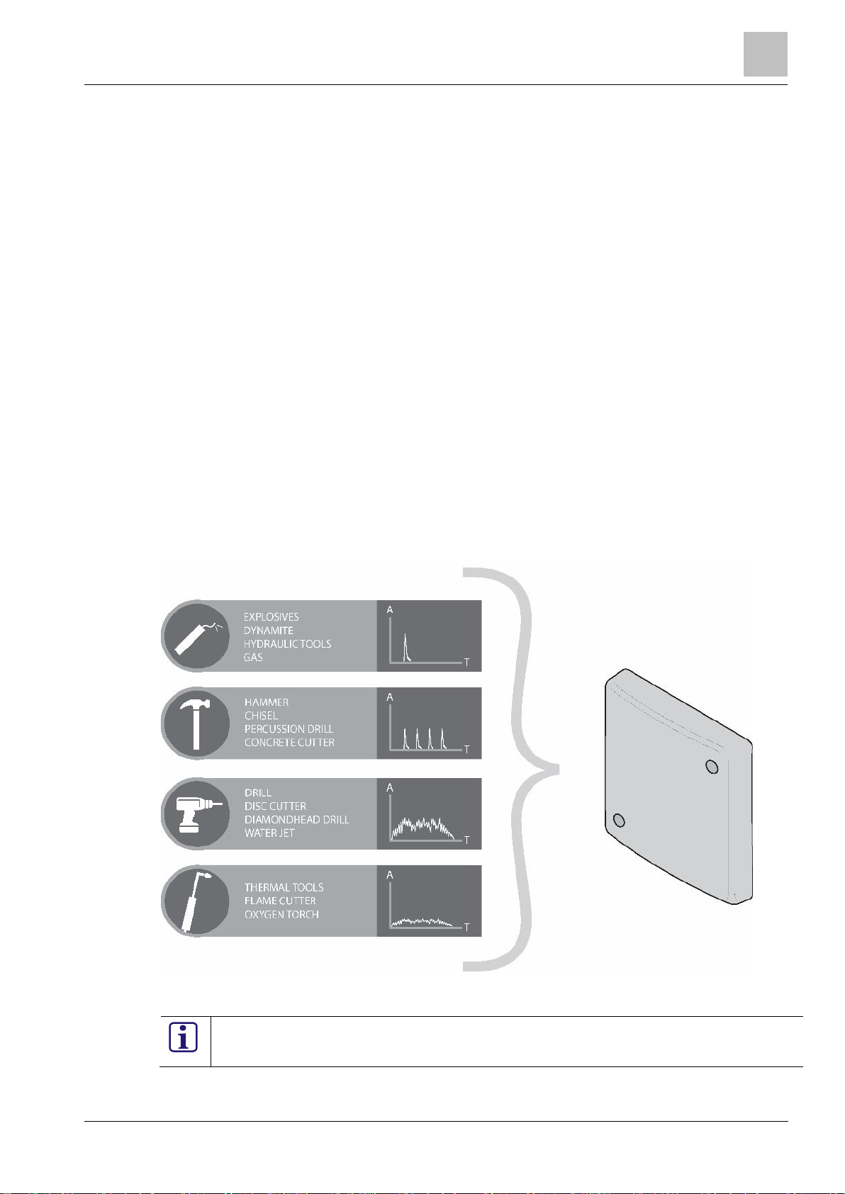
The ISN-SM-xx range of detectors are capable of detecting attacks using many different methods,
including tamper protection, temperature surveillance (for thermal attacks), shock detection (impacts on the detector or monitored surface), access times (automatic or manual access without
creating an alarm, controlled via the intruder panel), and integration alarms (low level frequencies
detected over a longer period of time).
The critical component of all ISN-SM-xx seismic detectors is a patented bimorph sensor that provides unrivalled detection, unwanted alarm immunity and reliability. ISN-SM-xx detectors are compatible with most intruder systems but peak performance is achieved when the detectors are connected to the Bosch Security Systems SPC panel. See Section 9 Interface to SPC Panel/System
for more information.
Detection of an attack is primarily achieved by monitoring the surfaces of the protective enclosure
and detecting any vibrations that are carried through the structure. Vibration signals are evaluated
based on amplitude (signal strength), frequency, and duration to differentiate between an attack
and general background signa ls. This patented technology enables swift and reliable detection of
any attempt to gain unauthorised entry to the protected space. With several different detector options, an unrivalled range of accessories, and an extensive range of programming options, the
Bosch Security Systems ISN-SM-xx range of seismic detectors offers reliable detection and the
highest immunity to unwanted alarms.
F
igure 1-1: ISN-SM-xx Seismic detectors – Attack types
crete surfaces. Correct operation and performance of the detectors on other surfaces can-
Bosch Security Systems Seismic Detectors Application Guide I-200153-1
04.2016
3
General information
6
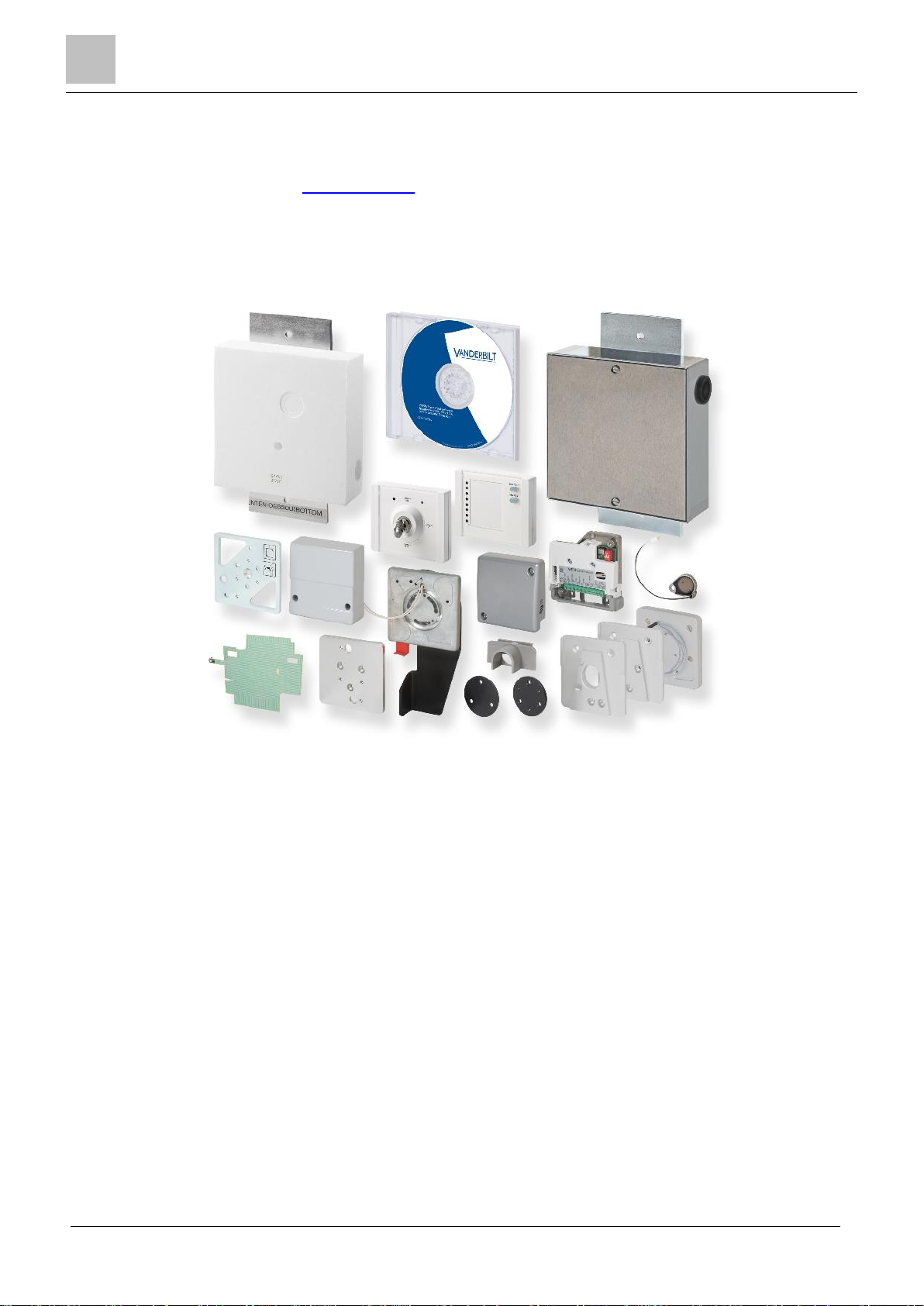
1.1 Detector and accessory overview
Additional information relating to the Bosc h Security Systems Seismic range of detectors and accessories is available on www.spiap.com.
Bosch Security Systems Seismic Detectors Application Guide I-200153-1
F
igure 1-2: Detector and accessory overview
04.2016

Applications
3
7
2 Applications
Financial – Vaults, safes, ATM’s, night de-
posit boxes, coin cabinets
Commercial – Vending machines, file stor-
jewellery showcases
Military – Armouries, medical stores, file
ers
Heritage – Vaults, store rooms, statues,
show cases
Transportation – Ticket machines, ATM’s,
vaults, access hatches
Medical – Drug storage, vaults, personal
records, instrument stores, ATM’s
Anti-terror – Water treatment works, nuclear plants, power generation
Residential – Safes and gun cabinets
The Bosch Security Systems ISN-SM-xx range of seismic detectors offers detection solutions with a
wide range of applications.
2.1 Detector applications a nd a t t a ck profiles
The following table shows some of the more common applications for the detectors:
Applications Attack Types grouped by amplitude
profile
Explosions – Gas, dynamite, hydraulic tools
age, ATM’s, fuel dispensaries, ticket machines, show cases, bonded warehouses,
storage, intelligence storage, gates, barri-
E
lectric tools – Disc cutter, diamond head drill, high
pressure water
Mechanical attacks – Hammer, chisel, percussion drill,
concrete cutter
hermal Tools- Oxygen lance, flame cutter
T
U
nauthorised opening – Doors & gates
Table 2-1: Detector applications and attack profiles
Bosch Security Systems Seismic Detectors Application Guide I-200153-1
04.2016
3
Applications
8
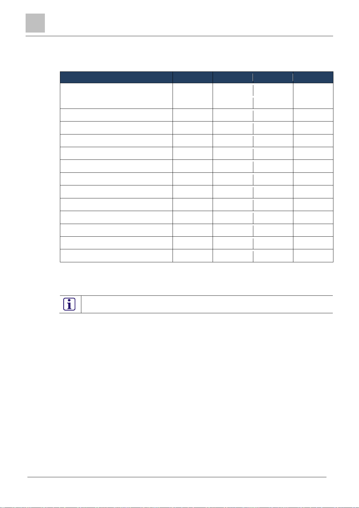
2.2 Detector selection
Applications
ISN-SM-30
ISN-SM-50
ISN-SM-80
ISN-SM-90
Ticket Machines
Yes
Vending Machines
Yes
Document/Filing Cabinets
Yes
Yes
Yes
Gun Cabinets
Yes
Yes
Yes
Chests
Yes
Night Deposit Boxes
Yes
Yes
Yes
Safes
Yes
Yes
Yes
Yes
LWS (Light Weight Safes) 1
Yes
Yes
Lobby ATMs
Yes
Yes
Yes
Yes
ATMs
Yes
Yes
Yes
Modular Vaults
Yes
Yes
Strong Room Vaults
Yes
Yes
Containers
Yes
Bonded Warehouses
Yes
Yes
Please note that Country specific approvals may exclude the use of certain detectors.
The following table shows some of the applications for the detectors together with a suggestion for
which detector from the range would provide the best detection solution for the application.
Table 2-2: Applications and recommended detectors
1
LWS Light Weight Safes can be constructed from a range of different composite materials.
Bosch Security Systems recommend that on-site tests are performed to ascertain the correct number
of detectors required for each LWS application.
See Section 10.1 Cross-reference chart for country-specific approvals for more information.
To compliment the excellent detection capabilities of the ISN-SM-xx detectors Bosch Security Systems offer a comprehensive range of accessories to provide additional security in the most challenging
of environments and applications. See Secti on 4 Installation - Accessories for more information.
Bosch Security Systems Seismic Detectors Application Guide I-200153-1
04.2016
Applications
3
9
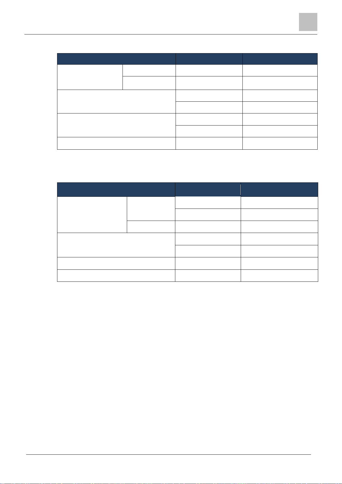
2.3 Steel applications and accessory options
Installation
On flat steel
Direct fix
N/A
On uneven steel
GMXP01
Test Method
Internal
GMXS1
External
GMXS5
Lock Protection
Safes
GMAS6
Vaults
GMXP3/Z
Additional Protection
Anti-drill foil
GMXD7
Recess Mount
Wall/Ceiling
GMXW0
Floor
GMXB0
Surface Mount
Mounting plate
GMXP01
Test Method
Internal
GMXS1
External
GMXS5
Additional Protection
Anti-drill foil
GMXD7
Cable Access
Plastic/Metal Conduit
GMXC2
Steel Application Options Accessory
Mounting plate1
Table 2-3: Steel applications and accessories
1
The GMXP0 Mounting plate is a mandatory accessory when installing a detector on uneven steel.
2.4 Concrete applications and ac c e s s ory options
Concrete Application Options Accessory
Installation
1
Table 2-4: Concrete applications and accessories
1
The GMXP0 Mounting plate is a mandatory accessory when surface mounting a detector on con-
crete.
Bosch Security Systems Seismic Detectors Application Guide I-200153-1
04.2016
3
Installation - Detectors
10
3 Installation - Detectors
Before installing a detector, Bosch Security Systems recommend that you consult the
For more information, see Section 5.4 Installation guidelines.
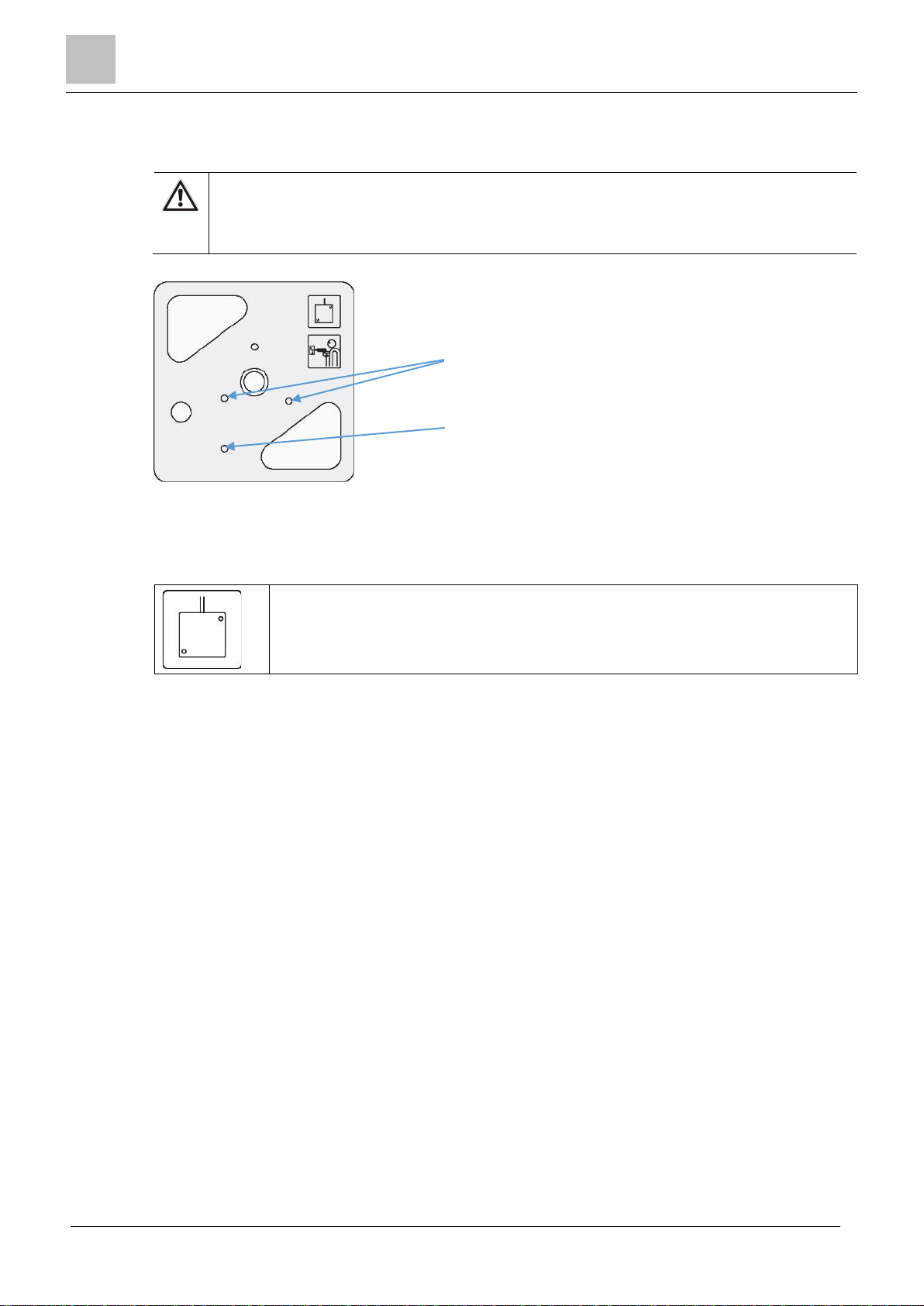
a) Cable access indicator
It is essential that the ISN-SM-xx detectors are installed correctly to provide the optimum performance
from the detector and to ensure that the required signals from the protected surface are transmitted to
the detector.
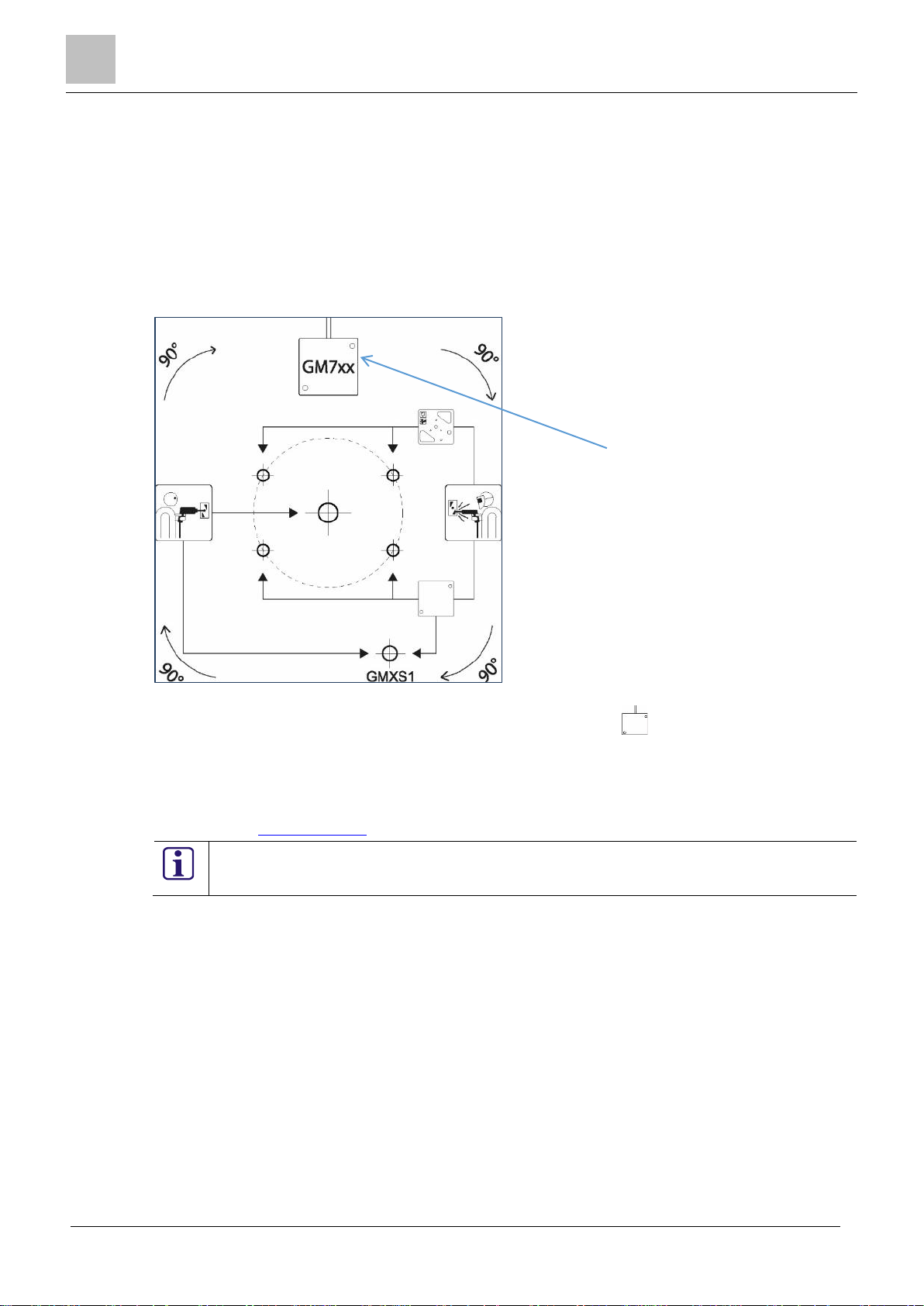
3.1 Drill template
A drill template is pro vided with each detector to assist with the correct method of securing the detector to the protected surface.
Figure 3-1: ISN-SM-xx drill template
a) The cable access point for the detector is depicted by the symbol , which shows the cable access at the top of the detector. The drill template can be turned through 90, 180 & 270⁰ to have the
cable access from the top, right, bottom or left side.
There is a 1:1 scale copy of the drill template located in Appendix 1: Drill template ISN-SM-xx.
The drill templates are also available as a download from the Bosch Security Systems Seismic micro-
site on SPIAP. www.spiap.com
guidelines for installation in this document.
3.2 Installation methods
This section contains useful information on the three main methods of detector installation.
• Direct installation on steel
• Indirect installation on steel
• Installation on concrete
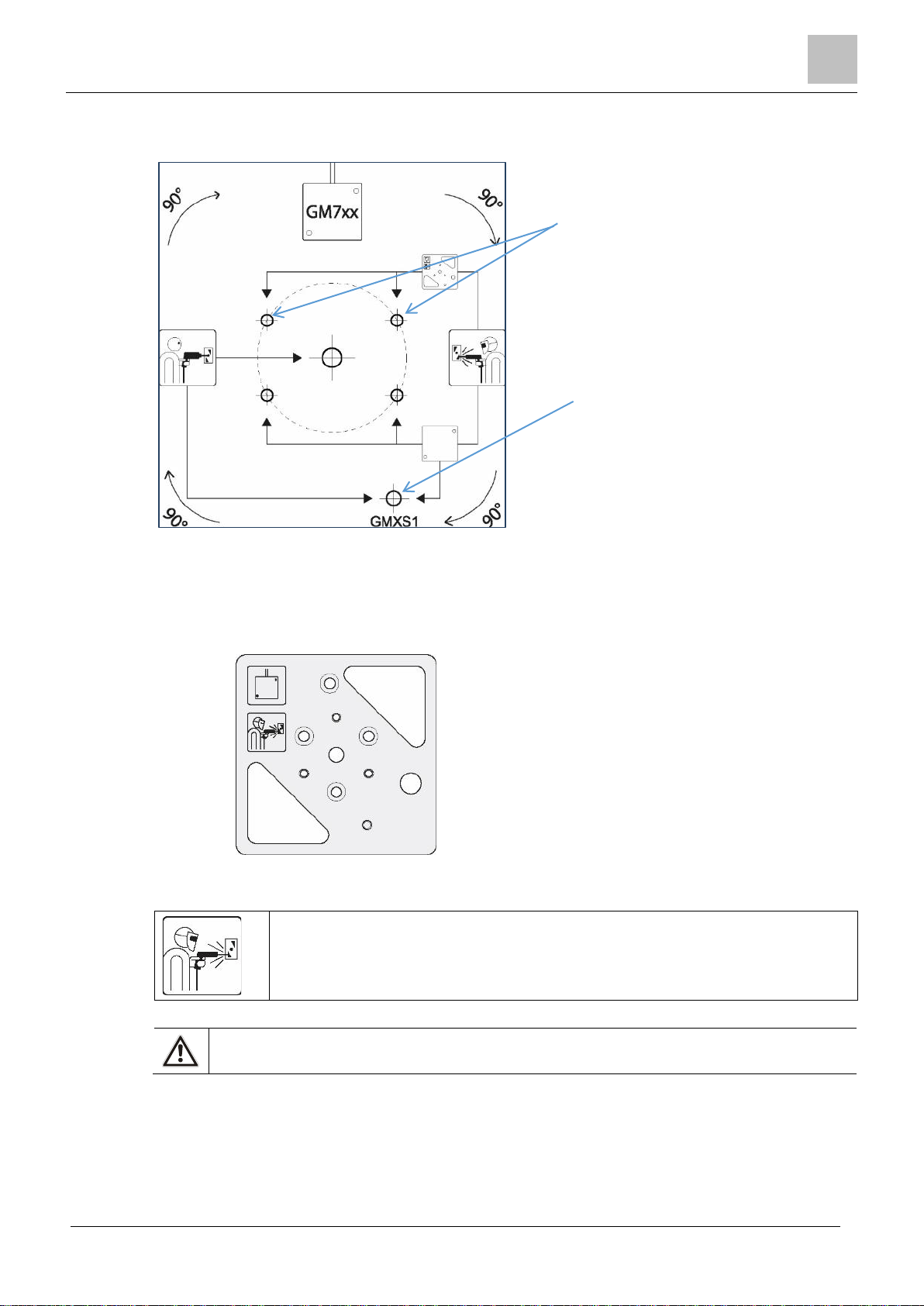
3.3 Detector installation onto flat st eel sur f a c e
Use this method to install a detector on a flat and even steel surface.
Remove all paint or grease from the steel surface to ensure that the detector has the optimum metal to
metal contact between the rear of the detector and the protected surface.
To mount the detector directly onto the steel surface, drill two holes to secure the detector, and one
hole to secure the GMXS1 test transmitter, if required.
Bosch Security Systems Seismic Detectors Application Guide I-200153-1
04.2016
Installation - Detectors
3
11
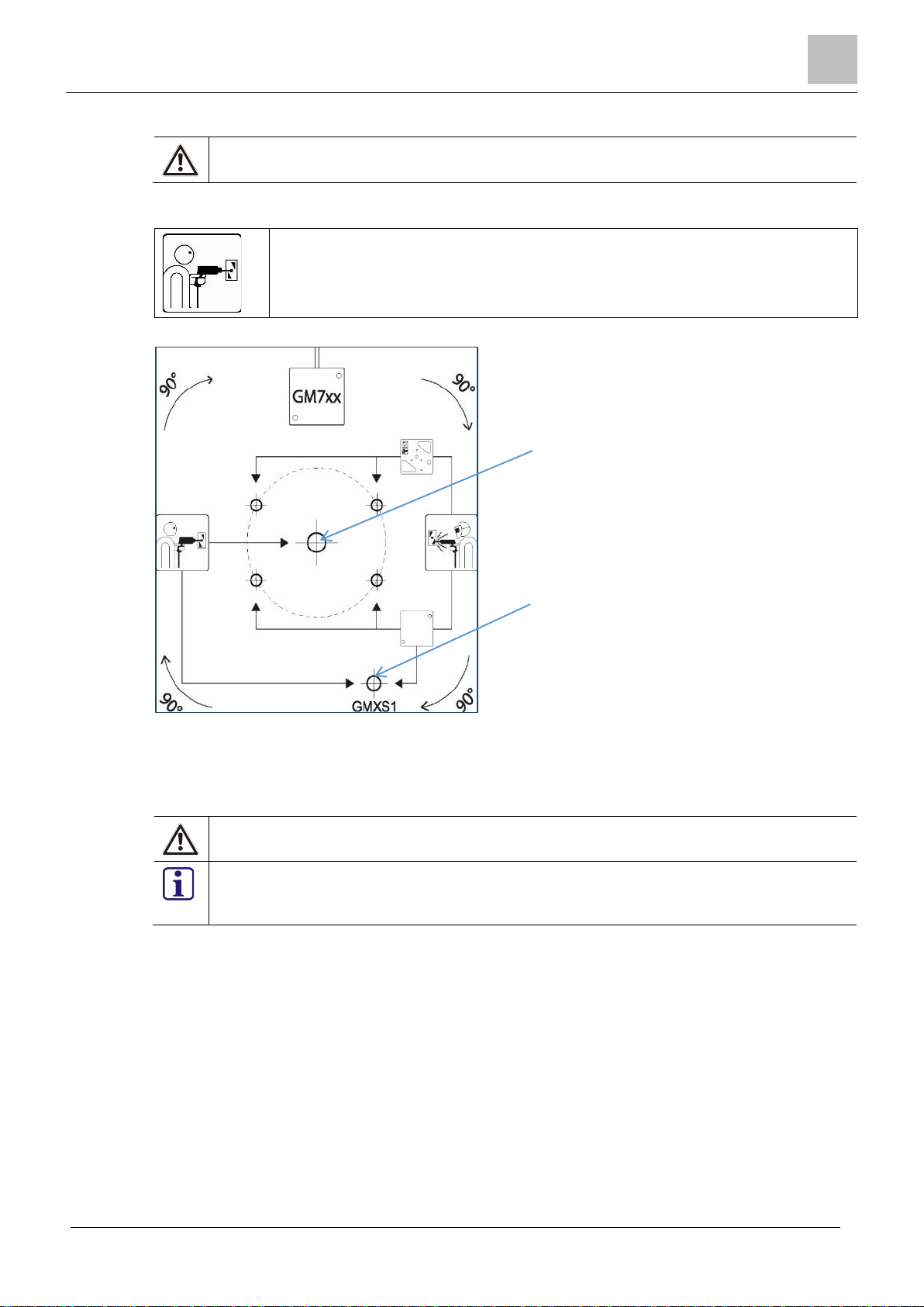
Drill two 3.2mm Ø holes at least
Use the ISN-SM-xx drill template (supplied with the detector) to correctly locate the drill holes for the
Drill one 3.2mm Ø hole at least
ISN-SM-xx detector and for the GMXS1 test transmitter.
6mm deep and then tap to M4
to secure the detector.
6mm deep and then tap to M4 to
secure the GMXS1 test transmitter
if required.
Figure 3-2: ISN-SM-xx drill template on flat steel
3.4 Detector installation on steel usi ng the GM X P 0 mount ing plate
The GMXP0 mounting plate must be used if the steel surface is uneven or the steel is reinforced. The
mounting plate can be welded or screwed to the protected surface. It is important to ensure that the
correct side is selected for the installation of the detector on to a steel surface.
GMXP0 mounting plate (weld side)
Figure 3-3: GMXP0 mounting plate
The weld symbol should be visibl e when wel d fixing the GMXP0 mounting plate to
a steel surface.
Remove all paint or grease from the steel surface to ensure that the rear of the GMXP0 has
the optimum metal to metal contact between the mounting plate and the protected surface.
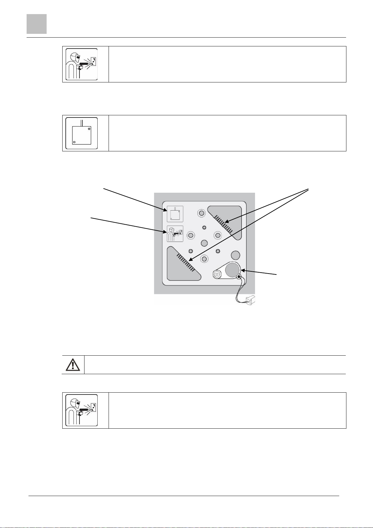
3.4.1 Weld fixing
Bosch Security Systems recommend weld fixing the GMXP0 mounting plate directly on to the clean,
paint-free area of the protected surface. This option provides the best acoustic coupling for the detection of vibration signals.
Ensure that the correct side of the mounting plate is selected for the type of fixing to the protected surface.
Bosch Security Systems Seismic Detectors Application Guide I-200153-1
04.2016
3
Installation - Detectors
12
The weld symbol should be visible when weld fixing the GMXP0 mounting plate to
GMXS1 test transmitter
fitted to pre-formed M4
mounting point
(recommended)
Cable access symbol showing
cable access from the top.
Weld symbol visible for weld
fixing.
Fillet welds applied to
long side of cut
Figure
a steel surface.
Before fixing the mounting plate to the protected surface, it is important to consider cable access to
the detector. If necessary, rotate the mounting plate to the correct orientation to give cable access to
the detector. When the mounting plate is welded to the protected surface it becomes a permanent fixture on that surface.
The cable access symbol indicates the direction of the cable access to the detector
when the detector is secured to the mounting plate. In the orientation shown here,
cable access to the detector is at the top of the installation.
Use two fillet welds, applied to the long side of the two cut-outs, to secure the mounting plate to the
protected surface.
-out
3.4.2 Screw fixing
If weld fixing to the protected surf ac e is not an option, the GMXP0 mounting plate can be secured by
screw fixing to a cle an, pai nt-free area of the protected surface.
se the weld side of the GMXP0 when screw fixing the GMXP0 mounting plate to a steel
U
surface.
Ensure that the correct side of the mounting plate is selected for the type of fixing to the protected surface.
Before fixing the mounting plate to the protected surface, it is important to consider cable access to
the detector. If necessary, rotate the mounting plate to the correct orientation to give cable access to
the detector.
3-4: GMXP0 mounting plate - weld fixing
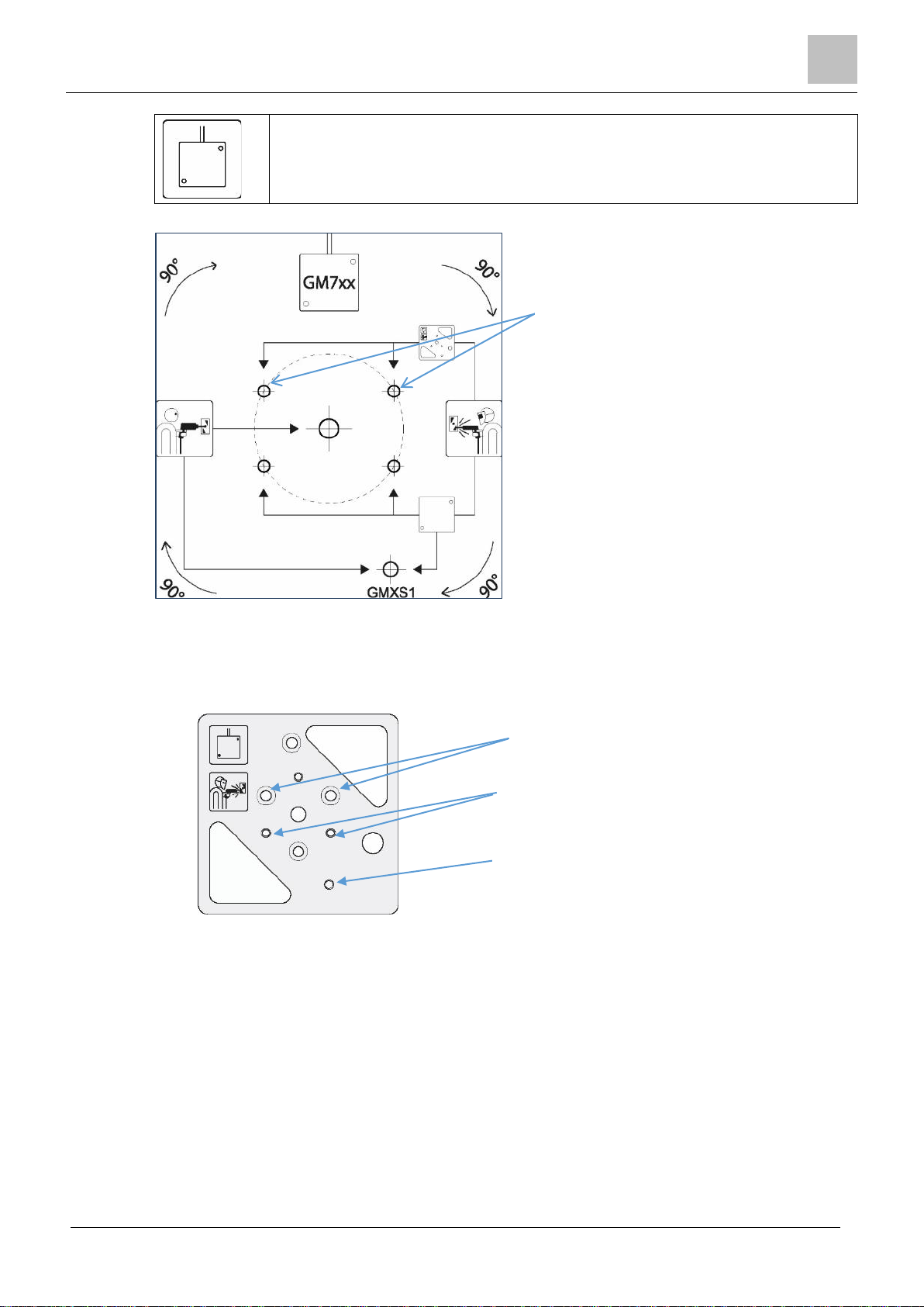
The weld symbol should be visible when screw fixing the GMXP0 mounting plate to
a steel surface.
Bosch Security Systems Seismic Detectors Application Guide I-200153-1
04.2016
Installation - Detectors
3
13
The cable access symbol indicates the direction of the cable access to the detector
A
B
when the detector is secured to the mounting plate. In the orientation shown here,
cable access to the detector is at the top of the installation.
Use the ISN-SM-xx drill template to mark the location of the required drill holes.
A
F
igure 3-5: ISN-SM-xx drill template for GMXP0 on steel
1. Use the ISN-SM-xx drill template to mark the correct location of the fixing holes (A), and drill
two 3.2mm Ø holes at least 6mm deep.
2. Tap each hole to M4.
3. Remove the drill template from the protected surface before fixing the GMXP0.
F
igure 3-6: GMXP0 screw fixing
4. Secure the GMXP0 through the holes (A) using 2 x M4 countersunk screws (provided wit
G
MXP0).
5. Mount the detector on the GMX P0 using the mounting holes provided (B).
6. Mount the GMXS1 internal test transmitter on the designated location on the GMXP0 (C) an
connect to the detector.
3.4.3 Glue Fixing
If weld or screw fixing to the steel surface is not an option, the GMXP0 mounting plate can be secured
by glue fixing to a clean area of the protected surface. For improved adhesion results the surface of
the protected surface should be scratched with a form of abrasive material or tool. The recommended
option for installation is to drill or weld the GMXP0 to the protected surface and to follow the installation guides throughout this document and the associated installation sheets.
C
h
d
Bosch Security Systems Seismic Detectors Application Guide I-200153-1
04.2016
3
Installation - Detectors
14
Tests have been completed using UniBond Repair Power Expoxy Permanent Adhesive – Metal. Material Reference 2000912. Other forms of adhesive exist and local tests should be performed if any other
type of adhesive is used.
A
GMXP0 mounting plate must be used when this installation option is selected.
Apply the adhesive to the drill side of the GMXP0 when glue fixing the GMXP0 mounting
plate to a steel surface.
DO NOT apply the adhesive to the rear of the detector.
A
B
F
igure 3-7: GMXP0 mounting plate (drill side)
Before fixing the mounting plate to the protected surface, it is important to consider cable access to
the detector. If necessary, rotate the mounting plate to the correct orientation to give cable access to
the detector. When the mounting plate is glued to the protected surface it becomes a permanent fixture on that surface.
The cable access symbol indicates the direction of the cable access to the detector
when the detector is secured to the mounting plate. In the orientation shown here,
cable access to the detector is at the top of the installation.
1. Protect the detector mounting holes (A) and the GMXS1 mounting hole (B) by placing tap e
ov
er the holes to prevent ingress of the adhesive.
2. Apply adhesive to the drill side of the GMXP0. Do not place excessive amounts of adhesiv
e
on the plate as it will overspill onto the protected surface when the plate is applied.
3. Use clamps or tape to secure the mounting plate in pos ition for the initial setting time. Under
normal environmental conditions, the Uni Bon d Repair Po wer Expoxy Permanent Adhesive –
Metal. Material Reference 2000 912 takes approximately 10 minutes to set for normal handli
and
2 hours for rough handling.
Notes
1. Carefully follow the instructions supplied with the adhesive for securing products and all health &
safety advice.
2. When using the adhesive, it is not imperative that the paint is removed prior to the adhesive bei
applied but the surface should be clean.
3. Securing the GMXP0 with a ISN-SM-90 detector using adhesive will have a slight performanc
ssue when the detector is set for low shock sensitivity. This reduction in sensitivity should be
i
e
considered as part of the design criteria. All other detectors and their associated settings remain
unaffected by this installation method.
4. As part of any routine inspection, the mounting plates should receive special attention to ensure
t
hat there has not been a deterioration of the adhesive material.
ng
ng
3.5 Indirect ins t a llation on concrete
Bosch Security Systems Seismic Detectors Application Guide I-200153-1
The GMXP0 mounting plate must be used to secure a ISN-SM-xx seismic detector to a concrete surface.
Use the ISN-SM-xx drill template (supplied with the detector) to correctly locate the cable access for
the detector and to locate the drill holes for the GMXP0 mounting plate detector and for the GMXS1
test transmitter (if required).
04.2016
Installation - Detectors
3
15
Use the drill side of the GMXP0 when fixing the GMXP0 mounting plate to a concrete sur-
A
B
face.
Ensure that the correct side of the mounting plate is selected for the type of fixing to the protected surface.
The drill symbol should be visible when fixing the GMXP0 mounting plate to a concrete surface.
F
igure 3-8: ISN-SM-xx drill template for GMXP0 on concrete
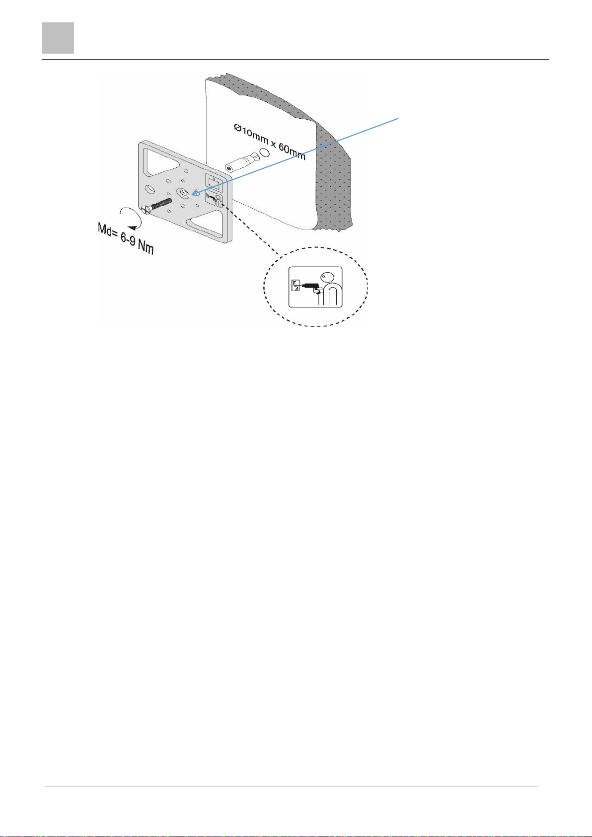
1. Drill a 10mm Ø x 60mm hole (A) and insert the steel expansion plug, supplied with t
G
MXP0.
2. If the GMXS1 test transmitter is required, drill a 5mm Ø x >22mm hole (B) and insert the
G
MXS1 brass expansion plug.
Do not use any other screw or expansion plug for either of these fixings.
It is essential that the GMXS1 test transmitter is secured directly to the concrete and that it
does not make contact with the GMXP0 or the detector. This is to ensure that the correct
test signal is applied to the protected surface when the GMXS1 is activated.
he
Bosch Security Systems Seismic Detectors Application Guide I-200153-1
04.2016
3
Installation - Detectors
16
The centre hole of the GMXP0
has a counter sunk recess on
cations.
the drill side for concrete appli-
F
igure 3-9: GMXP0 on concrete
3. Use the M6 x 47mm screw to secure the GMXP0 to the steel expansion plug.
4. Use the M4 x 21mm screw to secure the GMXS1 to the brass expansion plug.
5. Mount the ISN-SM-xx detector on to the GMXP0.
Bosch Security Systems Seismic Detectors Application Guide I-200153-1
04.2016

Installation - Accessories
4
17
4 Installation - Accessories
4.1 GMXP0 mounting plate
F
igure 4-1:GMXP0 mounting plate
The GMXP0 is used to provide a secure connection between the detector and the protected surface.
The GMXP0 is a double-sided metal plate suitable for welding, screwing or gluing to the protected
surface.
The GMXP0 is mandatory for installations on uneven steel, reinforced steel and concrete surfaces.
4.2 GMXS1 internal test transmitter
igure 4-2: GMXS1 internal test transmitter
F
The GMXS1 internal test transmitter is installed with a detector. The GMXS1 enables a user to test
the detector from an external source, via a switched input. Testing is usually performed from the
intruder panel but it may also be performed from another source.
Activation of the GMXS1 is interpreted by the detector as a thermal lance attack as this form of attack is the most difficult to detect.
The GMXS1 must be installed in the recommended location in close proximity to the seismic detector to enable a good acoustic connection between the test transmitter and the detector. The location of the GMXS1 is determined by the drill template or the m ounti ng pla te. In both cases, the
GMXS1 is located under the cover of the ISN-SM-xx detector.
The GMXS1 may be used for both steel and concrete applications.
Bosch Security Systems Seismic Detectors Application Guide I-200153-1
04.2016
4
Installation - Accessories
18
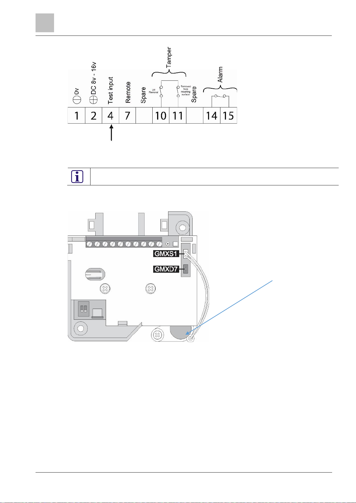
F
test transmitter
igure 4-3: Detector input for GMXS1 testing
Apply the required input to terminal 4, which is selectable as part of the detector programing options.
Active low = 0v applied to activate. Active high = 0v removed to activate.
When selecting the Active high option, it is essential to connect a permanent 0v to avoid unwanted
alarms. To activate, remove the 0v.
The input selection is only available through SensTool.
GMXS1 internal
Bosch Security Systems Seismic Detectors Application Guide I-200153-1
igure 4-4: ISN-SM-xx detector with GMXS1
F
04.2016
Installation - Accessories
4
19
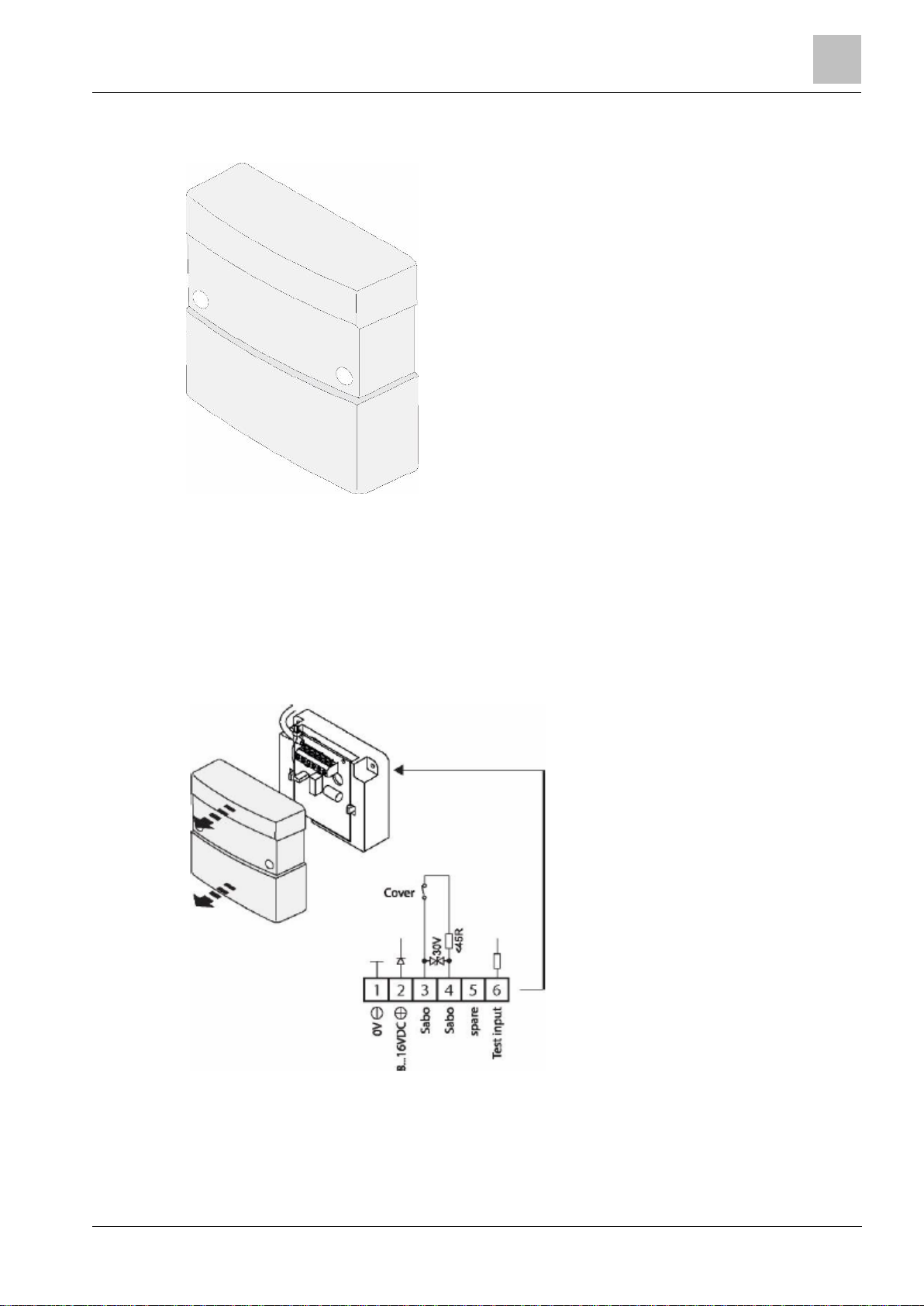
4.3 GMXS5 – External test transmitter
Figure
4-5: GMXS5 external test transmitter
he GMXS5 external test transmitter is mounted on the exterior of the protected area to enable a
T
functional check of the seismic detection system by simulating an external attack. During the test
period the GMXS5 creates a series of mechanical oscillations which are transmitted to the seismic
detector(s) as structure-borne sound. If the seismic detectors are correctly spaced and configured,
then the test is detected and an alarm is triggered.
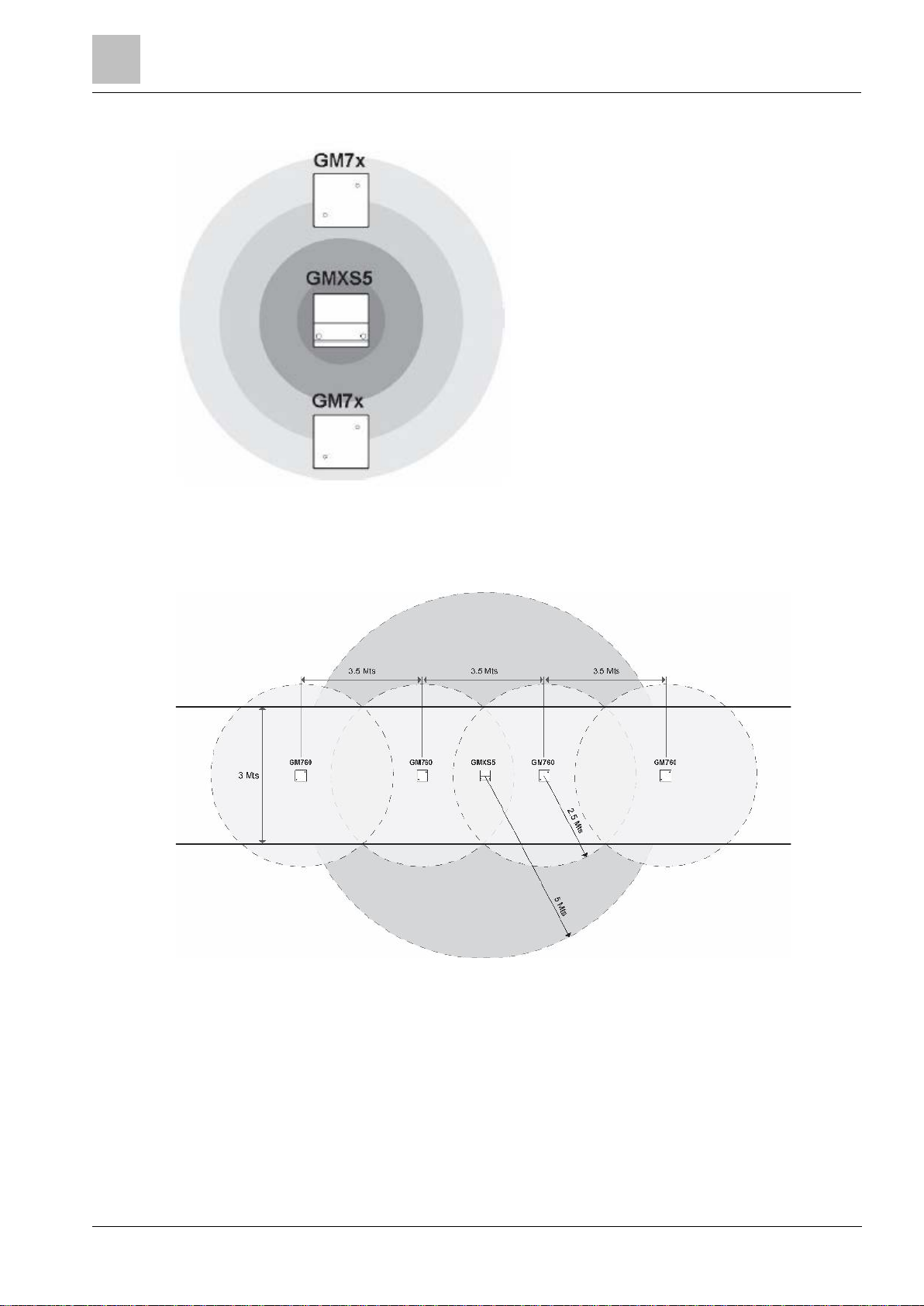
The GMXS5 has an operating radius that is directly linked with the detection radius of the detector
that is being tested. The GMXS5 is capable of testing multiple devices.
See Figure 4-8: Activate 4 detectors from a single GMXS5 for more information.
F
igure 4-6: GMXS5 Electrical connections
Figure 4-6 shows the electrical connection for the device, 12 VDC, tamper (Sabo) contacts and a
selectable switched input are the available connections.
Bosch Security Systems Seismic Detectors Application Guide I-200153-1
04.2016
4
Installation - Accessories
20
F
igure 4-7: GMXS5 transmission signals
Figure 4-7: GMXS5 transmission signals shows the transmission signals from the GMXS5, which
are strongest closest to the device but still detectable by ISN-SM-xx detectors if the signals are
within the detection radius of the detectors.
Bosch Security Systems Seismic Detectors Application Guide I-200153-1
F
igure 4-8: Activate 4 detectors from a single GMXS5
Figure 4-8: Activate 4 detectors from a single GMXS5 is a typical example of how to activate multiple detectors from a single GMXS5.
04.2016
Installation - Accessories
4
21
F
Concrete
ISN-SM-90
5m
Steel
ISN-SM-90
2m
Concrete
ISN-SM-80
5m
Steel
ISN-SM-80
2m
Concrete
ISN-SM-50
4m
Steel
ISN-SM-50
2m
Steel
ISN-SM-30
2m
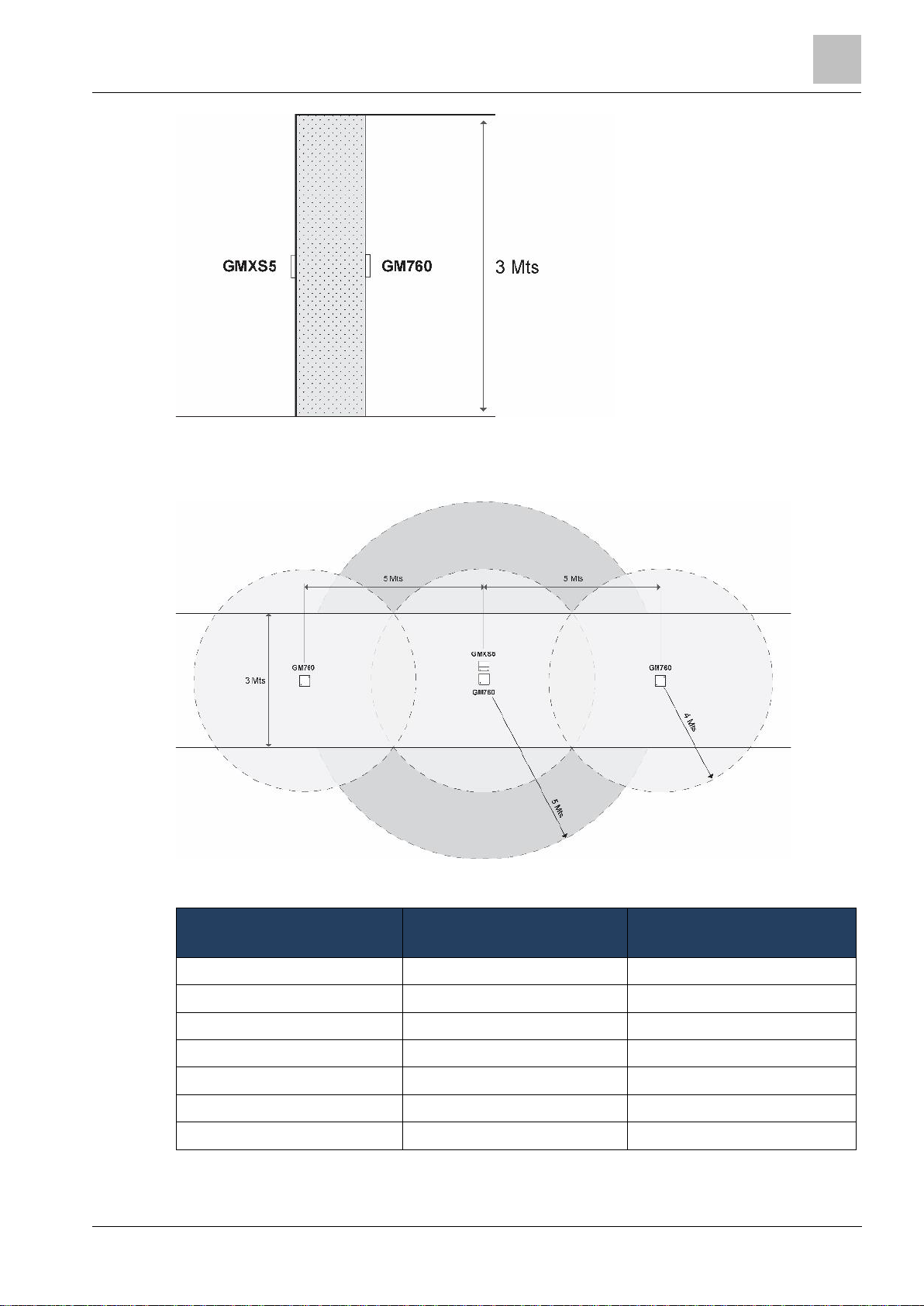
igure 4-9: External GMXS5 and internal ISN-SM-80
Figure 4-9 shows the detectors mounted internal to the protected space and the GMXS5 mounted
external to the protected space. This location provides a stringent test for the detectors as the test
signals from the GMXS5 have to travel through the wall.
Figure 4-10: Activate 3 detectors from a single GMXS5
Figure 4-10 is an example of how to activate multiple detectors from a single GMXS5.
Material Detector Effective Transmission
Diameter of the GMXS5
Table 4-1: GMXS5 transmission diameters
Bosch Security Systems Seismic Detectors Application Guide I-200153-1
04.2016
 Loading...