

Page 1
Intrusion Alarm Systems | ISC‑PDL1‑W18x Professional Series TriTech Detectors
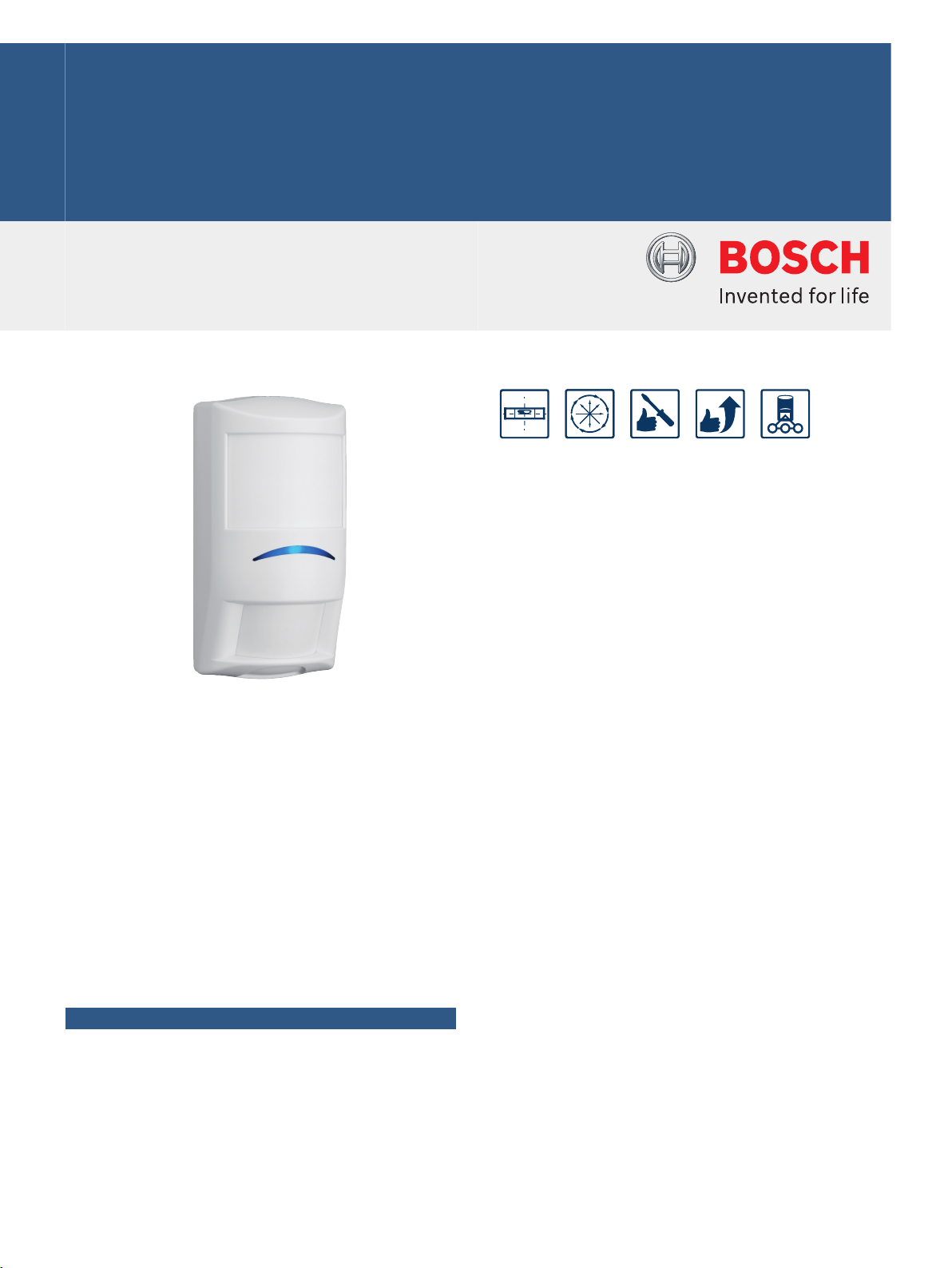
ISC‑PDL1‑W18x Professional Series
TriTech Detectors
www.boschsecurity.com
u 18 m x 25 m (60 ft x 80 ft) coverage, field selectable
to 8 m x 10 m (25 ft x 33 ft)
The ISC-PDL1-W18x Professional Series TriTech
Detectors are exceptionally suited for commercial
indoor applications. Sensor data fusion technology
ensures that the detectors send alarm conditions
based on precise information. Tri-focus optics
eliminate coverage gaps and respond efficiently to
intruders. The powerful combination of unique
features in the Professional Series delivers superior
catch performance and virtually eliminates false
alarms.
The self-locking two-piece enclosure, built-in bubble
level, flexible mounting height, and three optional
mounting brackets simplify installation and reduce
service time.
Functions
Sensor Data Fusion Technology
Sensor data fusion technology is a unique feature that
uses a sophisticated software algorithm to gather
signals from five sensors: two pyroelectric sensors,
range adaptive radar, a room temperature sensor, and
u EN50131-2-4 Grade 2 compliant
u Sensor data fusion technology
u Tri-focus optics technology
u Range adaptive radar
a white light level sensor. The microcontroller analyzes
and compares the sensor data to make the most
intelligent alarm decisions in the security industry.
Tri-focus Optics Technology
Tri-focus optics technology uses optics with three
specific focal lengths: long-range coverage, middlerange coverage, and short-range coverage. The
detector applies the three focal lengths to 86
detection zones, which combine to make 11 solid
curtains of detection. Tri-focus optics technology also
includes two pyroelectric sensors, which deliver twice
the standard optical gain. The sensors process
multiple signals to deliver precise performance
virtually free of false alarms.
Range Adaptive Radar
The microwave transceiver automatically adjusts its
detection thresholds based on input from the PIR
sensors. Integrating the target audience distance
information from the PIR significantly reduces false
alarms from the microwave Doppler radar.
Page 2
2 | ISC‑PDL1‑W18x Professional Series TriTech Detectors
Microwave Anti-mask
The detector sends a supervision‑trouble signal if
microwave reflective material is placed within 30.5 cm
(1 ft) of the detector.
Supervised Microwave and PIR
The detector provides single technology coverage if
the microwave subsystem fails.
Active White Light Suppression
An internal light sensor measures the level of light
intensity directed at the face of the detector. Sensor
data fusion technology uses this information to
eliminate false alarms from bright light sources.
Field Selectable Coverage (18 m x 25 m or 8 m x
10 m)
Installers can use a DIP switch to select 18 m x 25 m
or 8 m x 10 m (60 ft x 80 ft or 25 ft x 33 ft) coverage.
Dynamic Temperature Compensation
The detector automatically adjusts PIR sensitivity to
identify human intruders at critical temperatures.
Dynamic temperature compensation detects human
body heat accurately, avoids false alarms, and delivers
consistent catch performance at all operating
temperatures.
Cover and Wall Tamper Switch
When an intruder removes the cover or attempts to
separate the detector from the wall, a normally-closed
contact opens to alert the control panel.
Self-adjusting LED
The LED brightness adjusts automatically to the
surrounding light level. A blue light-emitting diode
(LED) indicates dual alarms and activates during a
walk test. A yellow LED indicates microwave
detection, and a red LED indicates PIR detection.
Remote Walk Test LED
Users can type a command through a keypad, a control
center, or programming software to remotely enable
or disable the walk test LED. Users can locally enable
or disable the walk test LED through the DIP switch.
Alarm Memory
Alarm memory flashes the alarm LED to indicate
stored alarms for use in multiple unit applications. A
switched voltage from the control panel controls the
alarm memory.
Solid State Relays
Solid state relays send silent alarm output signals to
provide a higher level of security and reliability. An
external magnet does not activate the relay. The solid
state relay uses less current than a mechanical relay,
providing longer standby capacity during a power loss.
Draft, Insect, and Small Animal Immunity
The sealed optic chamber provides immunity to drafts
and insects, reducing false alarms. Small animal
immunity reduces false alarms caused by animals less
than 4.5 kg (10 lb), such as rodents.
Remote Self Test
A remote self test initiates when the walk test input
switches to its true state. The alarm relay and alarm
LED activate for four seconds following a successful
test. The trouble relay activates, and the alarm LED
flashes following a failed test.
Input Power Supervision
When the power is lower than 8 V, a low input power
trouble condition activates the trouble relay and
causes the LED to flash. The trouble condition clears
automatically when power reaches or exceeds 8 V.
Trouble Memory
When the walk test input switches to its true state for
less than two seconds, LED flashes to indicate the
most recent trouble condition. If there is no trouble in
memory, the LED does not flash. After twelve hours, or
after the detector receives a second walk test pulse
for two seconds or less, the LED stops flashing and
the trouble memory clears.
Certifications and approvals
The detectors are designed to also comply with the requirements of:
Australia C-Tick
Region Certification
Australia SCEC eA1186637 [-W18G, -WA18G]
Europe CE 2004/108/EC EMC Directive (EMC),
EN50131EN50131-2-4:2008, Grade 2
Belgium INCERT B-509-0052/f [-W18G]
USA UL ANSR: Intrusion Detection Units
FCC (T3XISC-PDL1-W18G)
Italy IMQ (CA12.00833) [-G]
Canada IC (1249A-W18G)
France AFNOR 2830390400A1 [-W18H]
AFNOR 2830390400 [-W18G]
China CCC 2009031901000559 [-W18G]
Sweden INTYG Nr11-850 [-W18G]
Brazil ANATEL 1282-06-1855 [-W18G]
the Netherlands
REQ 07223002/AA/00 [-W18G]
2006/95/EC Low-Voltage Directive
(LVD), 1999/5/EC Radio equipment and
Telecommunications Terminal Equipment (R&TTE), 2011/65/EU Restriction
of the use of certain hazardous substances in electrical and electronic equipment [-W18G, -W18H]
(UL639), ANSR7: Intrusion Detection
Units Certified for Canada (cULus) [W18G]
Page 3

0f t
0f t
0f t
0f t
0f t
0 f t
7f t
7f t
7f t
7f t
7f t
7f t
13f t
13f t
13f t
13f t
13f t
10f t
20f t
20f t
20f t
20f t
20f t
26f t
26f t
26f t
26f t
26f t
33f t
33f t
33f t
33f t
33f t
39f t
39f t
39f t
39f t
39f t
46f t
46f t
46f t
46f t
46f t 52f t
52f t
52f t
59f t
59f t
59f t
0m
0m
0m
0m
0m
0m
2m
2m
2m
2m
2m
4m
4m
4m
4m
4m
3m
2m
6m
6m
6m
6m
6m
8m
8m
8m
8m
8m
10m
10m
10m
10m
10m
12m
12m
12m
12m
12m
14m
14m
14m
14m
14m
16m
16m
16m
18m
18m
18m
2
3
1
1
2
3
1
1
2
3
90°
2
3
2
2
2
3
3
0f t
0f t
0f t
0f t
0f t
0f t
0m
0m
0m
0m
0m
0m
2m
2m
2m
2m
2m
2m
7f t
7f t
7f t
7f t
7f t
7f t
10f t3m
4m
4m
4m
4m 6m
6m
6m
6m
6m
8m
8m
8m
20f t
13f t
13f t
13f t
13f t
13f t
20f t
20f t
20f t
20f t
26f t
26f t
26f t
4m
90°
3 | ISC‑PDL1‑W18x Professional Series TriTech Detectors
Installation/configuration notes
Mounting Considerations
The recommended mounting height is 2 m to 3 m (7 ft
to 10 ft).
Use an optional B328 Gimbal-mount Bracket or B335-3
Low-profile Swivel-mount Bracket to surface-mount
the detector on a flat wall or in a corner.
Use an optional B338 Universal Ceiling Bracket to
mount the detector on the ceiling.
Wiring Considerations
Recommended wire size is 0.2 mm2 to 1 mm2 (26 AWG
to 16 AWG).
Parts included
Quantity Component
1 Detector
2 Flat-head screws
2 Screw anchors
1 Nylon cable tie
1 Pattern Mask
1 Installation Guide
Technical specifications
Electrical
Power Requirements
Voltage (Operating): 9 VDC to 15 VDC
Current (Maximum): < 25 mA
Long-range Coverage 18 m x 25 m (60 ft x 80 ft)
Selectable Short-range Coverage 8 m x 10 m
(25 ft x 33 ft)
Current (Standby): 13 mA
Outputs
Relay: Solid state relay, normally-closed (NC)
contacts power supervised.
3 W, 125 mA, 25 VDC,
resistance < 10 Ω.
Tamper: Normally-closed (NC) contacts (with
cover on) rated at 25 VDC, 125 mA
maximum.
Connect tamper circuit to 24-hour
protection circuit.
Trouble: Solid‑state relay normally-closed (NC)
contacts.
Mechanical
Enclosure Design
Color: White
Dimensions: 136 mm x 69 mm x 58 mm
(5.25 in. x 2.75 in. x 2.25 in.)
Material: High-impact ABS plastic
Indicators
Alarm Indicator: • Blue LED for TriTech alarms
Page 4

4 | ISC‑PDL1‑W18x Professional Series TriTech Detectors
• Yellow LED for microwave
detection
• Red LED for PIR detection
Zones
Zones: 86
Frequency Information
Radio Frequency
Interference (RFI) immunity:
No alarm or setup on critical
frequencies in the range from 26 MHz
to 1 GHz at 50 V/m.
Environmental
Relative Humidity: 0 to 95%, non-condensing
Temperature (Operating
and Storage):
Environmental Class II EN 50130-5
Protection Rating: IP41, IK04 (EN 60529, EN 50102)
-29°C to +55°C (-20°F to +130°F)
For UL Certificated installations, 0°C to
+49°C (+32°F to +120°F)
Ordering information
ISC‑PDL1‑W18G Professional Series TriTech Detector
Provides PIR and microwave, 18 m x 25 m (60 ft x 80
ft) coverage. 10.525 GHz frequency.
Order number ISC-PDL1-W18G
ISC‑PDL1‑W18H Professional Series TriTech Detector
Provides PIR and microwave, 18 m x 25 m (60 ft x 80
ft) coverage. 10.588 GHz frequency. For use in France
and United Kingdom.
Order number ISC-PDL1-W18H
Accessories
B328 Gimbal‑mount Bracket
Mounts on a single-gang box and allows rotation of a
detector. Wires are hidden inside.
Order number B328
B335-3 Swiveling low-profile mount
Swiveling, low-profile, plastic mount for wall mounting.
The vertical swivel range is +10° to -20°, while the
horizontal swivel range is ±25°. Available in triple
packs.
Order number B335-3
B338 Universal Ceiling‑mount Bracket
Swiveling plastic mount for ceiling mounting. The
vertical swivel range is +7° to -16°, while the horizontal
swivel range is ±45°.
Order number B338
Page 5

5 | ISC‑PDL1‑W18x Professional Series TriTech Detectors
Represented by:
Americas: Europe, Middle East, Africa: Asia-Pacific: China: America Latina:
Bosch Security Systems, Inc.
130 Perinton Parkway
Fairport, New York, 14450, USA
Phone: +1 800 289 0096
Fax: +1 585 223 9180
security.sales@us.bosch.com
www.boschsecurity.us
Bosch Security Systems B.V.
P.O. Box 80002
5617 BA Eindhoven, The Netherlands
Phone: + 31 40 2577 284
Fax: +31 40 2577 330
emea.securitysystems@bosch.com
www.boschsecurity.com
Robert Bosch (SEA) Pte Ltd, Security
Systems
11 Bishan Street 21
Singapore 573943
Phone: +65 6571 2808
Fax: +65 6571 2699
apr.securitysystems@bosch.com
www.boschsecurity.asia
Bosch (Shanghai) Security Systems Ltd.
201 Building, No. 333 Fuquan Road
North IBP
Changning District, Shanghai
200335 China
Phone +86 21 22181111
Fax: +86 21 22182398
www.boschsecurity.com.cn
Robert Bosch Ltda Security Systems Division
Via Anhanguera, Km 98
CEP 13065-900
Campinas, Sao Paulo, Brazil
Phone: +55 19 2103 2860
Fax: +55 19 2103 2862
latam.boschsecurity@bosch.com
www.boschsecurity.com
© Bosch Security Systems 2014 | Data subject to change without notice
2607960459 | en, V21, 23. Dec 2014
 Loading...