

Photobeam 5000
ISC-FPB1-W60QF, ISC-FPB1-W120QF, ISC-FPB1-W200QF
en Installation and Operation Guide


Photobeam 5000 Table of Contents | en 3
Table of contents
1
1.1 About documentation 4
1.2 Bosch Security Systems, Inc 4
2
2.1 Features 5
2.2 Photobeam overview 6
2.3 Console overview 7
2.4 Transmitter/receiver dimensions 8
3
3.1 Beam spread 9
3.2 Pole mount installation 10
3.3 Wall mount installation 12
4
4.1 Terminal strip overview 13
4.2 Wiring distance 14
4.3 Wiring routes 14
5
5.1 Selectable beams 16
5.2 Selectable AND/OR Gate 16
5.3 Level LED 16
5.4 EDC (Environmental Discrimination Circuit) 16
5.5 Beam interruption time 17
5.6 Beam power control 17
5.7 High Density 18
6
7
7.1 Group selection 25
7.2 Channel selection 27
7.3 Synchro wiring 29
7.4 Stacking examples 30
7.4.1 Single stacking 30
7.4.2 Double stack 30
7.4.3 Triple stack 31
7.4.4 Quadruple stack 32
8
8.1 Level LED – alignment of the Upper Beam 35
8.2 Level LED - alignment of the Lower Beam 35
8.3 Volt meter alignment 36
9
10
10.1 Additional information 39
11
12
Introduction 4
System overview 5
Installation 9
Wiring 13
Special features 16
Setup 21
Installing multiple sets (stacking) 25
Optical alignment 35
Operational check 38
Troubleshooting 39
Certifications 40
Specifications 41
Bosch Security Systems, Inc. Installation and Operation Guide 2015.01 | 02 | F.01U.303.478

4 en | Introduction Photobeam 5000
1
1.1
1.2
Introduction
This document contains information that a trained installer needs to install the Photobeam
5000 quad-beam photoelectric detector contained inside the packaging.
About documentation
Copyright
This document is the intellectual property of Bosch Security Systems, Inc. and is protected by
copyright. All rights reserved.
Trademarks
All hardware and software product names used in this document are likely to be registered
trademarks and must be treated accordingly.
Bosch Security Systems, Inc
Use the serial number located on the product label and refer to the Bosch Security Systems,
Inc. website at http://www.boschsecurity.com/datecodes/.
Manufacturing date information is contained in digit no 1 – 3: DDD.
2015.01 | 02 | F.01U.303.478 Installation and Operation Guide Bosch Security Systems, Inc.

Photobeam 5000 System overview | en 5
2
2.1
System overview
The ISC-FPB1-W60QF, ISC-FPB1-W120QF, and ISC-FPB1-W200QF are quad-beam
photoelectric detectors designed for indoor and outdoor applications. Consisting of a
separate transmitter and receiver, an alarm is activated when a person passes through the
beams. Combination of features and adjustable parameters allow for better catch
performance, lower false alarm rates, and reduced effects of environmental disturbances.
Features
For stable operation, the detectors are equipped with the following feautres:
100% Sensitivity Allowance
Maintains stable operation even if 99% of beam energy is cut, for example by rain, fog, frost,
and so on.
Quad Beam Detection
Fewer false alarms caused by birds and other small animals because all four beams must be
blocked simultaneously to cause an alarm.
Beam Power Control
Select the appropriate beam intensity relative to the detection range to minimize reflection on
nearby walls and cross-talk with other detectors.
Beam Interruption Time Control
Use to change the beam interruption time to best fit the application.
Bosch Security Systems, Inc. Installation and Operation Guide 2015.01 | 02 | F.01U.303.478
2
1
1
4
5
6
7
8
9
10
11
10
9
7
8
3
13
12
6 en | System overview Photobeam 5000
2.2
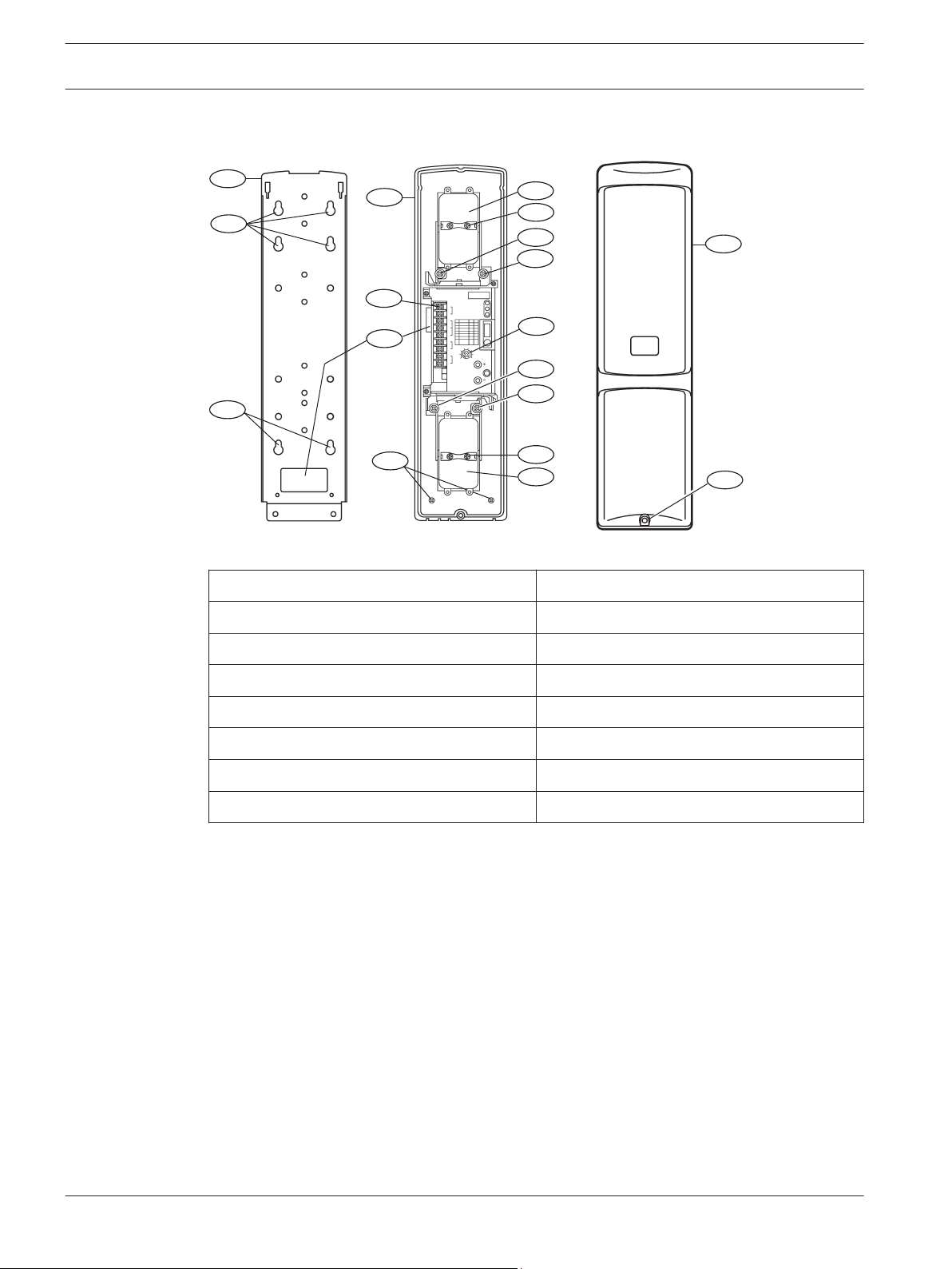
Photobeam overview
Figure 2.1: Photobeam components overview
Callout ー Description
Callout ー Description
1 ー Mounting holes 8 ー Optical alignment
2 ー Mounting plate 9 ー Vertical adjustment
3 ー Device securing screws 10 ー Horizontal adjustment
4 ー Wire entry 11 ー Console
5 ー Wiring terminals 12 ー Cover
6 ー Detector 13 ー Cover securing screws
7 ー Optical module
2015.01 | 02 | F.01U.303.478 Installation and Operation Guide Bosch Security Systems, Inc.
2
3
6
4
8
7
1
5
9
Photobeam 5000 System overview | en 7
2.3
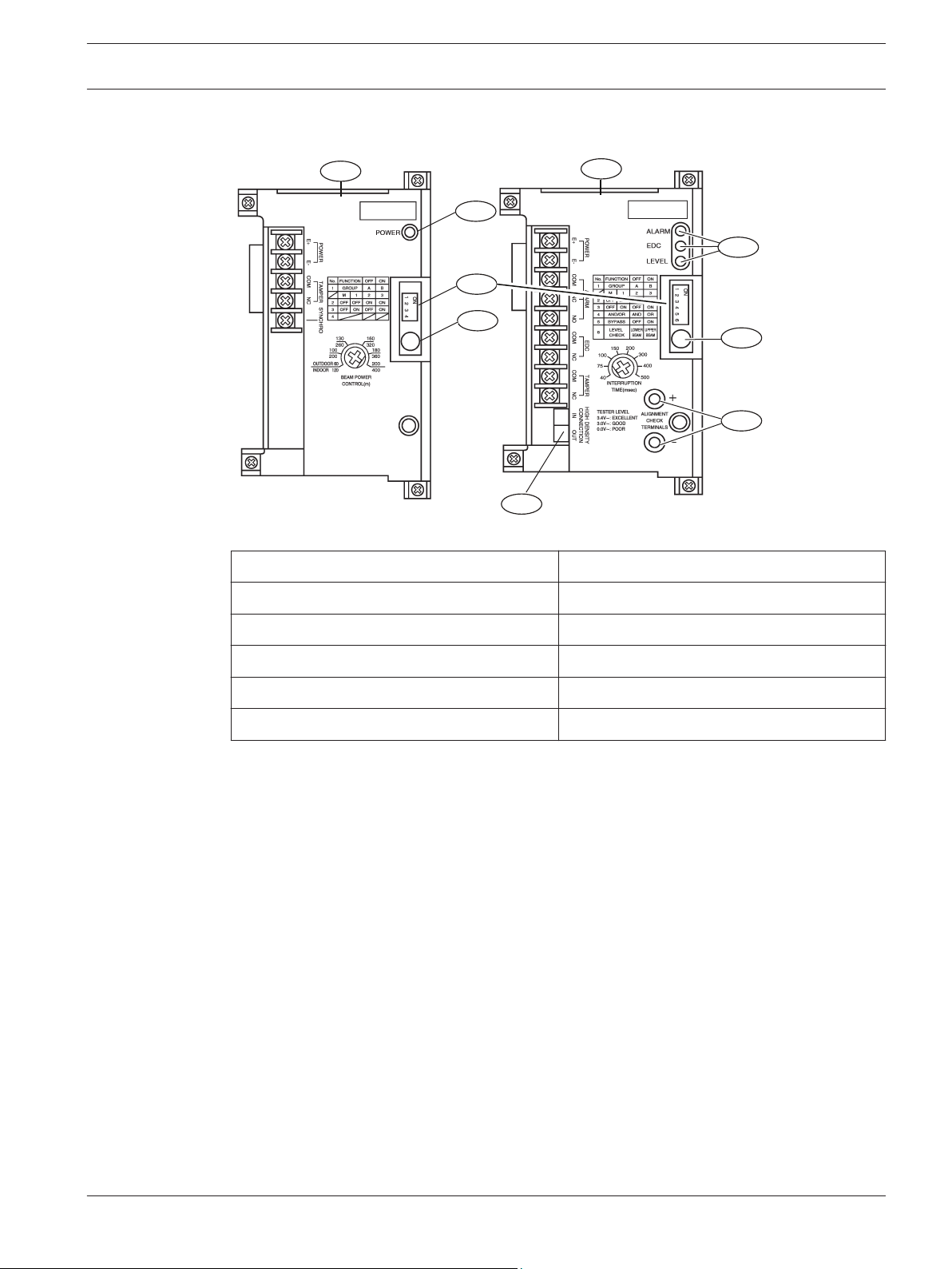
Console overview
Figure 2.2: Console components overview
Callout ー Description
Callout ー Description
1 ー Transmitter console 6 ー Status indicators
2 ー Power indicator 7 ー Sensitivity control
3 ー Function switches 8 ー ALIGNMENT CHECK TERMINALS
4 ー BEAM POWER CONTROL 9 ー HIGH DENSITY terminals
5 ー Receiver console
Bosch Security Systems, Inc. Installation and Operation Guide 2015.01 | 02 | F.01U.303.478
1
103 mm (4.0 in)
19.3 mm
(0.75 in)
398 mm (15.66 in)
244 mm (9.60 in)
96 mm (3.77 in)
77.1 mm
(3.03 in)
337.7 mm (13.29 in)
56 mm
(2.20 in)
220 mm (8.66 in)
39 mm
(1.5 in)
39.7 mm
(1.56 in)
2
3
4
8 en | System overview Photobeam 5000
2.4
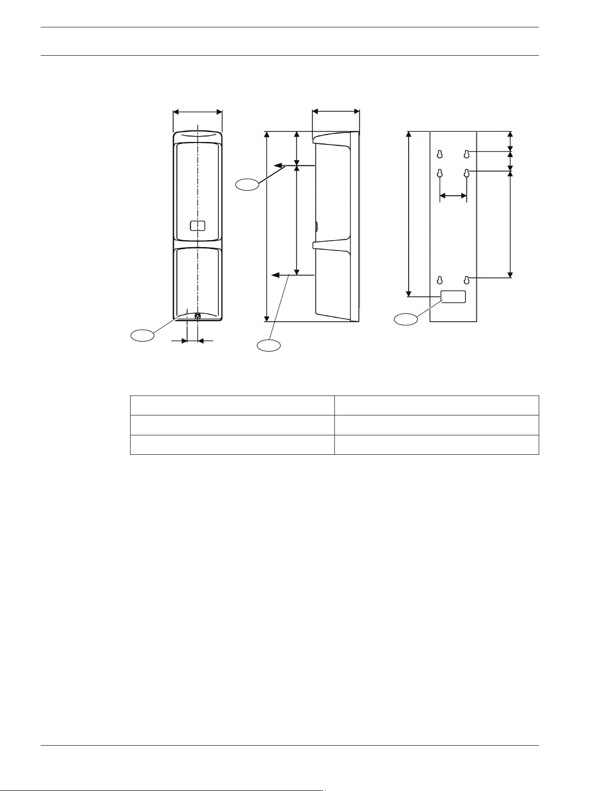
Transmitter/receiver dimensions
Figure 2.3: Transmitter/receiver dimensions
Callout ﹘ Description
Callout ﹘ Description
1 ー Knockout wire entrance 3 ー Center of the Upper Beam
2 ー Center of the Lower Beam 4 ー Wire entrance
2015.01 | 02 | F.01U.303.478 Installation and Operation Guide Bosch Security Systems, Inc.
1
5
4
3
2
Photobeam 5000 Installation | en 9
3
3.1
Installation
Prior to installing the devices, please review the installation considerations below:
– Install in an area that is clear of objects
– Install the transmitter/receiver within the maximum protection range of the model
– Do not install:
– Receivers into intense sources of light (for example, rising and setting sun)
– On movable surfaces subject to vibrations
– Detectors where immersion to water, corrosive liquids, or exposure to high levels of
dust can occur
– Detectors in close proximity to strong electromagnetic noises
– Do not use detectors with other photobeam detectors or receivers
– Do not disassemble or modify this detector
– Do not install while the power is on
– Avoid extreme temperature and humidity ranges as defined in the products specifications
– Avoid installing detectors near magnets and/or magnetized materials
– Avoid beam interference between other units when multiple units are installed
– Use the selectable beam’s feature when stacking detectors
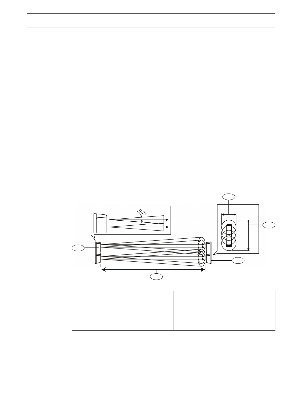
Beam spread
The beam spread angle is ±0.7 °from the transmitter to the receiver. Refer to the diagram and
table below to determine the installation conditions.
Figure 3.1: Beam distance and spread
Callout ﹘ Description
1 ー Transmitter 4 ー Receiver
Callout ﹘ Description
2 ー Horizontal spread (B) 5 ー Distance (A)
3 ー Vertical spread (C)
Bosch Security Systems, Inc. Installation and Operation Guide 2015.01 | 02 | F.01U.303.478
1
2
10 en | Installation Photobeam 5000
Distance, horizontal and vertical spread values: (A) / (B) / (C)
Metric Imperial unit
20 m / 0.5 m / 0.8 m 65 ft / 1.6 ft / 2.6 ft
40 m / 1.0 m /1.3 m 13.1 ft / 3.2 ft / 4.2 ft
60 m / 1.5m / 1.8 m 196 ft / 4.9 ft / 5.9 ft
80 m / 2.0 m / 2.2 m 262 ft / 6.5 ft / 7.2 ft
100 m / 2.5 m / 2.7 m 328 ft / 8.2 ft / 8.8 ft
120 m / 3.0 m / 3.2 m 393 ft / 9.8 ft / 10.4 ft
140 m / 3.5 m / 3.7 m 459 ft / 11.4 ft / 12.1 ft
160 m / 4.0 m / 4.2 m 524 ft / 13.1 ft / 13.7 ft
180 m / 4.5 m / 4.7 m 590 ft / 14.7 ft / 15.4 ft
200 m / 5.0 m / 5.2 m 656 ft / 16.4 ft / 17.0 ft
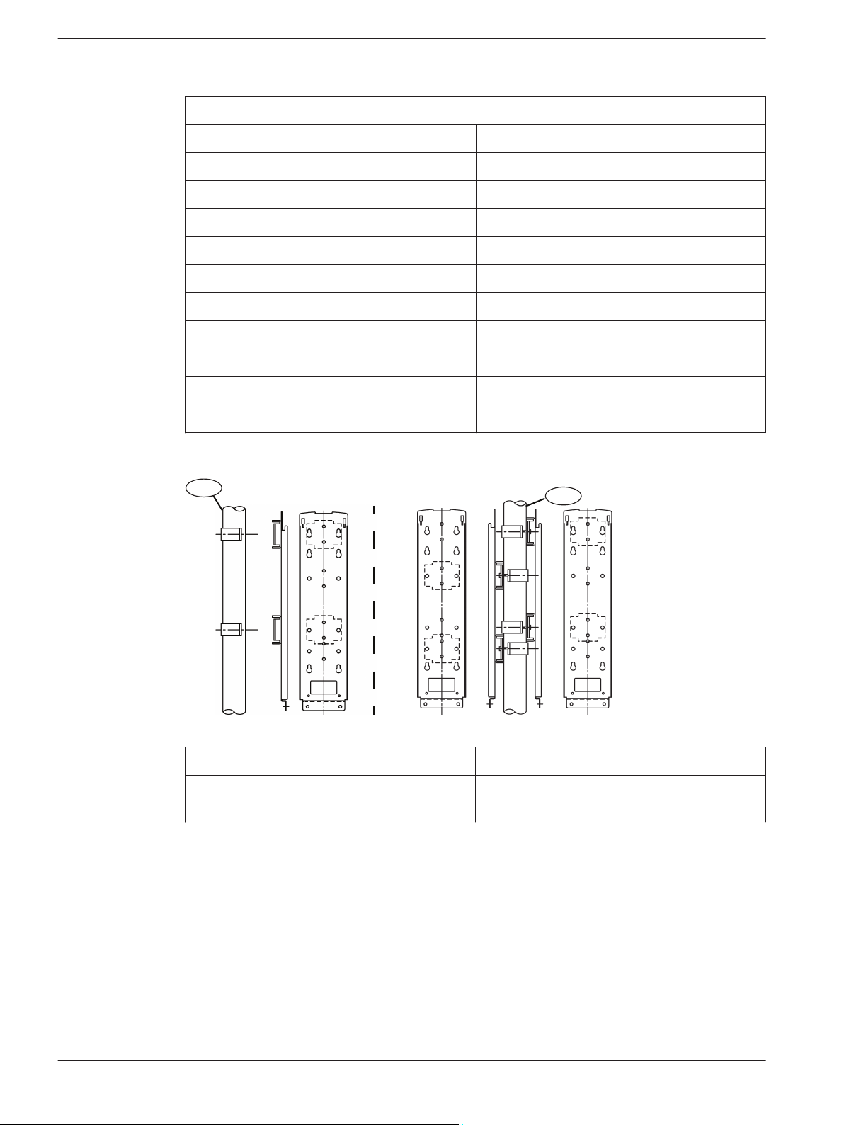
3.2
Pole mount installation
Figure 3.2: Pole mounting view
Callout ﹘ Description
1 ー Diameter 38.0 – 42.7 mm (1.50 – 1.68
in)
Attaching the mounting bracket:
1. Choose an appropriate mounting location for the devices. Install the mounting poles with
a clear line-of-sight between the transmitter and receiver.
2. Loosen the transmitter’s cover mounting screw and remove the cover.
3. Loosen the two base mounting screws and remove the mounting plate by sliding it down.
4. Attach the mounting hardware to the mounting plate using the clamping screws. Refer to
the figure below.
Callout ﹘ Description
2 ー Back-to-back pole mounting
2015.01 | 02 | F.01U.303.478 Installation and Operation Guide Bosch Security Systems, Inc.
1
3
2
4
2
3
1
Photobeam 5000
Installation | en 11
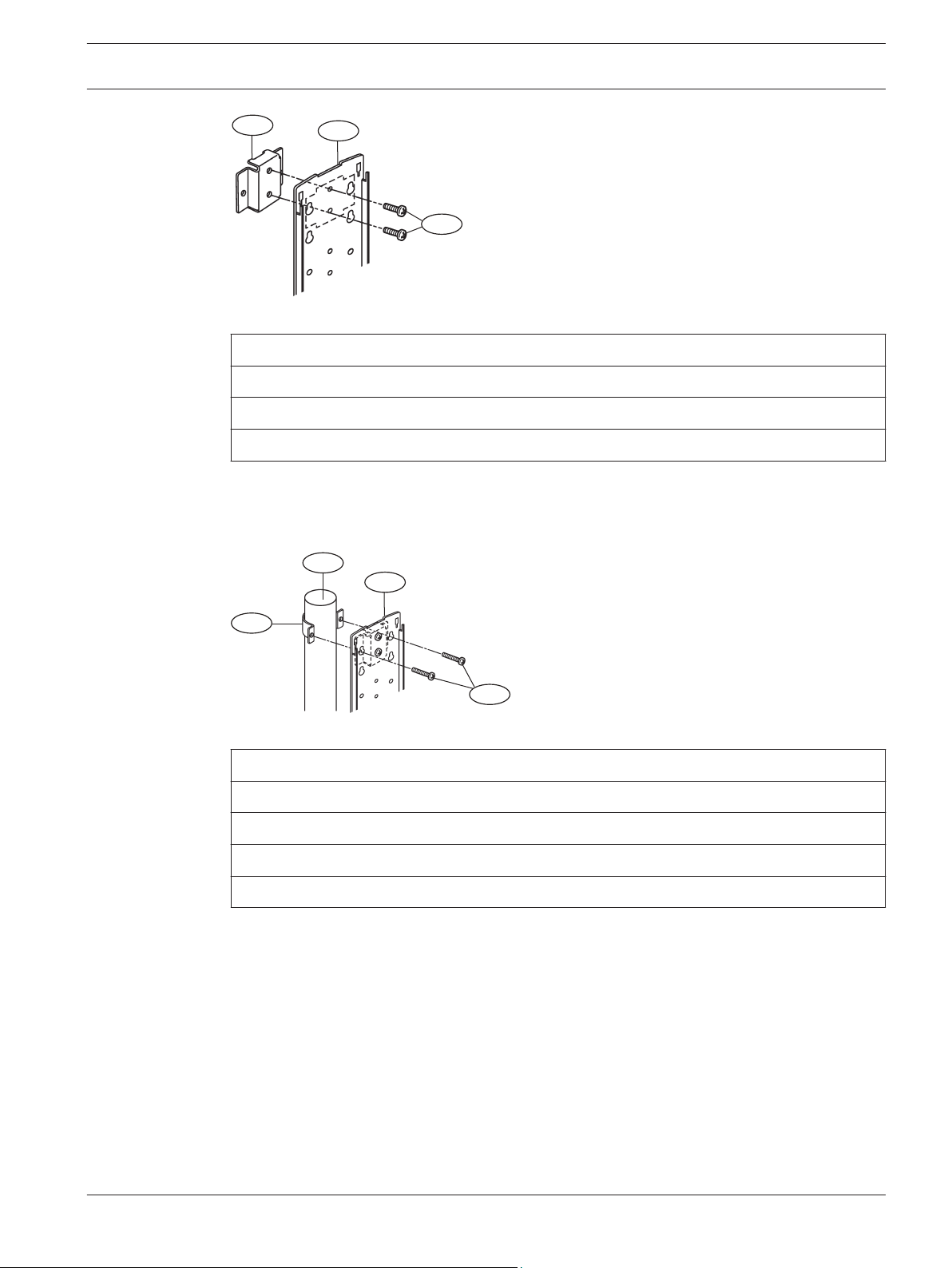
Figure 3.3: Attaching the mounting bracket
Callout ﹘ Description
1 ー Mounting hardware
2 ー Mounting plate
3 ー Clamping screws (short)
Attaching the mounting plate:
1. Attach the mounting plate to the poles using the U-clamps.
2. Use the U-clamps and clamping screws to attach the mounting plate firmly to the poles.
Figure 3.4: Attaching the U-clamp
Callout ﹘ Description
1 ー U-clamp
2 ー Mounting pole
3 ー Mounting plate
4 ー Clamping screws (long)
Wire routing:
1. Route the wire through the wire entry location of the mounting plate, leave enough wire
to reach the terminal strip.
2. Route the wire through the transmitter’s wire entry.
3. Slide the transmitter onto the mounting plate, and secure using the included screws.
4. Repeat this procedure for the receiver, verify line-of-sight with the transmitter.
5. Wire to the terminal strips. Refer to Wiring for wiring procedures.
Bosch Security Systems, Inc. Installation and Operation Guide 2015.01 | 02 | F.01U.303.478
!
1
4
2
6
5
3
12 en | Installation Photobeam 5000
Caution!
Ensure that the pole mount installation is secure and stable. Failure to do so may result in
personal injury, or damage the device.
3.3
Wall mount installation
Installing the transmitter and receiver:
1. Remove the cover and mounting plate from the transmitter.
2. Route the wire through the mounting plate wire entry if the wire is routed through a wall
opening. If the wire is routed on the wall surface, knock-out the thin wall wire hole at the
bottom of the transmitter and cover. Route the wire through the opening after the
mounting plate is secured onto the wall.
3. Secure the mounting plate to the wall surface.
4. Route the wire through the detector wire entry location.
5. Secure the transmitter to the mounting plate.
6. Wire to the terminal strips. Refer to Wiring for wiring procedures.
7. Repeat this procedure for mounting the receiver.
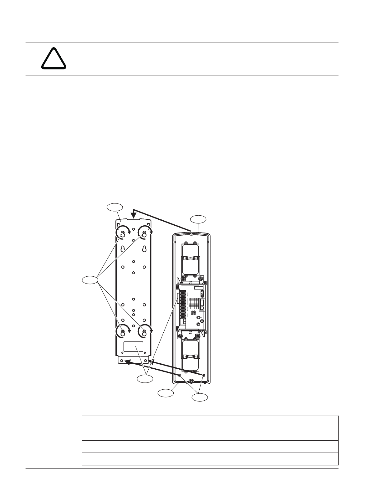
Figure 3.5: Wall mount installation
Callout ー Description
1 ー Mounting screws 4 ー Device securing screws
2 ー Mounting plate 5 ー Knockout
3 ー Detector 6 ー Wire entry
2015.01 | 02 | F.01U.303.478 Installation and Operation Guide Bosch Security Systems, Inc.
Callout ー Description
!
1
2
3
4
3
56
4
Photobeam 5000 Wiring | en 13
4
Wiring
Refer to Terminal strip below for transmitter/receiver terminal locations. Use duct
pipes for outdoor wiring. Do not use aerial wiring.
Caution!
Complete all electrical connections and inspect them prior to applying power.
Notice!
Tamper and EDC terminals should be connected to a 24-hour supervisory loop
Notice!
Power is to be provided by a UL Listed burglar alarm power supply or burglar alarm control
panel. In case of power failure, the power supply or control unit shall have a minimum of 4
hours of standby power.
Notice!
All wiring is to be in accordance with the National Electric Code, ANSI/NFPA 70.
4.1
Notice!
This system should be tested at least once a week to ensure proper function.
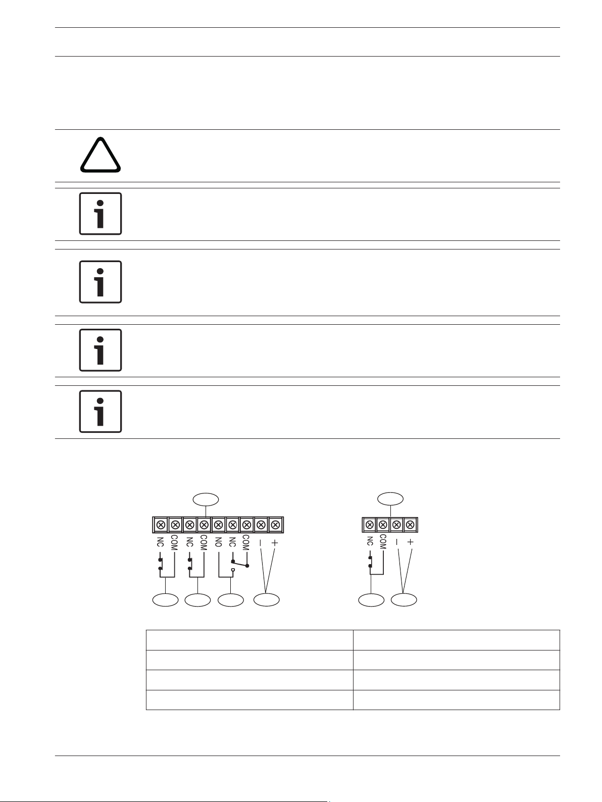
Terminal strip overview
Figure 4.1: Terminal strip component overview
Callout ﹘ Description
1 ー Receiver 4 ー Tamper
2 ー Transmitter 5 ー Alarm output
3 ー Power (non-polarized) 6 ー EDC output
Callout ﹘ Description
Bosch Security Systems, Inc. Installation and Operation Guide 2015.01 | 02 | F.01U.303.478
14 en | Wiring Photobeam 5000
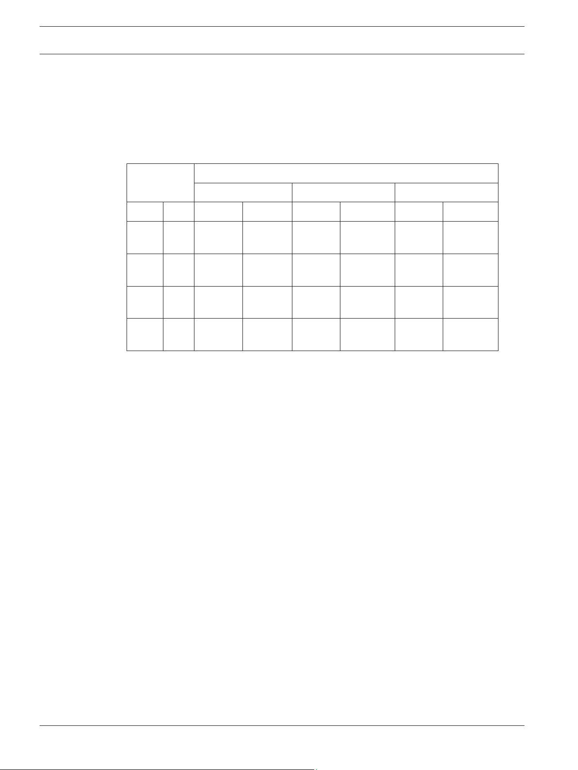
4.2
Wiring distance
Refer to the table to determine the minimum wire gauge for a single sensor system (one
transmitter and one receiver). The distances specified are between the power source and the
last (farthest) unit on the single wire run. For multiple detector configurations, divide the wire
distance in the table by the number of systems in the configuration (1 system = 1 transmitter
and 1 receiver).
Wire Gauge Maximum wiring distance
ISC-FPB1-W60QF ISC-FPB1-W120QF ISC-FPB1-W200QF
AWG Ø mm 12V 24V 12V 24V 12V 24V
22 0.65 90 m
(295 ft)
19 0.90 170 m
(557 ft)
17 1.14 320 m
(1049 ft)
14 1.62 570 m
(1870 ft)
820 m
(2690 ft)
1600 m
(5249 ft)
2930 m
(9612 ft)
5150 m
(18896 ft)
80 m
(262 ft)
170 m
(557 ft)
310 m
(1017 ft)
550 m
(1804 ft)
790 m
(2591 ft)
1550 m
(5085 ft)
2830 m
(9284 ft)
4980 m
(16338 ft)
80 m
(262 ft)
160 m
(524 ft)
300 m
(984 ft)
530 m
(1738 ft)
770 m
(2526 ft)
1500 m
(4921 ft)
2740 m
(8989 ft)
4820 m
(15813 ft)
4.3
Wiring routes
Refer to the graphics below for wiring routes examples. The illustrations depict both one, and
two sets of detector systems on a single wire run.
The graphics below show simple examples of wiring concepts, depicting how to power the
transmitter and receiver pairs, and how to combine alarm outputs. Local regulatory
requirements and technical parameters specific to a connected control panel determine the
exact details of the wiring. Review local regulations and the connected control panels
technical documentation before planning wire routes and connections. Selecting the proper
wire routes and gauges depend on the number of devices, overall distance, and voltage drop
parameters for each individual device.
2015.01 | 02 | F.01U.303.478 Installation and Operation Guide Bosch Security Systems, Inc.

4
1
5
2
3
4
1
5
4
3
2
3
2
Photobeam 5000 Wiring | en 15
Figure 4.2: Wiring for one set on the run
Callout ﹘ Description Callout ﹘ Description
1 ー Power output 4 ー Control panel
2 ー Transmitter 5 ー Alarm input. The COM and NC terminals
on the unit are the outputs, they connect to a
control panel input.
3 ー Receiver
Figure 4.3: Wiring for two sets on a single run
Callout ﹘ Description Callout ﹘ Description
1 ー Power output 4 ー Control panel
2 ー Transmitter 5 ー Alarm input. The COM and NC terminals
on the unit are the outputs, they connect to a
control panel input.
3 ー Receiver
Notice!
The BH12T heater is an optional device. Refer to the BH12T installation instructions (P/N: W.
97.2195) for more information.
Bosch Security Systems, Inc. Installation and Operation Guide 2015.01 | 02 | F.01U.303.478

16 en | Special features Photobeam 5000
5
5.1
5.2
Special features
Refer to the following for sensitivity adjustments.
Selectable beams
Crosstalk occurs when multiple beams are stacked or when used in long distances which
might cause a missed alarm (no catch). The devices are equipped with 8 different selectable
beam channels (2 Groups and 4 Channels) to prevent crosstalking. The selectable beam
channel feature allows the receiver to ignore the beams received from other transmitters
when the installation requires multiple devices to be placed in an area where a receiver is in
the beam spread of multiple transmitters. For more information on crosstalking, refer to
Installing multiple sets (stacking), page 25.
Selectable AND/OR Gate
Environmental conditions might require higher false alarm tolerance against smaller objects
passing through the detector's line of sight. To do this, set the AND/OR gate option to AND
gate mode that only causes an alarm condition when all four infrared beams are interrupted
simultaneously.
High Security applications might require the detection of smaller objects passing through the
detector's line of sight. To do this, set the AND/OR gate option to OR gate mode that causes
an alarm condition when either the upper two beams or the lower two beams are interrupted.
Use the selectable dip switches to choose the AND/OR GATE option on the receiver.
5.3
5.4
Level LED
The Level LED shows the beams energy level received during alignment. As more beam energy
is received, the illumination time shortens as follows: ON => OFF once => OFF twice => OFF
three times => Flashing => ON three times => ON twice => ON once => OFF.
When the LED turns off, the alignment is complete.
Refer to Console overview for Status Indicator locations (callout #6).
EDC (Environmental Discrimination Circuit)
The EDC generates a signal when the beam power level is significantly reduced due to
environmental conditions such as fog or rain. Two Bypass switch features are used at the
receiver, Bypass Switch Off, and Bypass Switch On.
The inability to operate for more than 3 seconds due to environmental conditions is defined as
a “Poor Environmental Condition.”
Switch Condition Description
Off When poor
environmental conditions
present:
When either optical
module is blocked for 3
or more seconds:
The EDC LED turns on and the EDC output activates.
Alarm signal is generated upon further loss of the beam
energy.
The EDC LED turns on and the EDC output activates. No
alarm is generated.
2015.01 | 02 | F.01U.303.478 Installation and Operation Guide Bosch Security Systems, Inc.

Photobeam 5000 Special features | en 17
Switch Condition Description
When both optical
modules are blocked for
The alarm LED turns on and an alarm signal is generated.
EDC LED turns on and EDC output activates.
3 or more seconds:
On When poor
environmental conditions
present:
When either optical
module is blocked for 3
or more seconds:
When both optical
modules are blocked for
3 or more seconds:
The EDC LED turns on and the EDC output activates.
Alarm LED turns on after further loss of beam energy but
does not generate an alarm signal.
The EDC LED turns on and provides a EDC signal. Alarm
LED turns on without generating an alarm signal if
another optical module is blocked.
The alarm LED turns on and alarm signal is generated.
EDC LED does not turn on and does not activate the EDC
output. It is recommended to connect the EDC output to
a trouble input point at the control panel. It is
recommended to check the system any time the EDC
relay has been activated.
Notice!
Connect the EDC to an input circuit and check the system any time the EDC relay is activated.
5.5
5.6
Notice!
The EDC feature was not investigated by Underwriters Laboratories (UL).
Beam interruption time
The beam interruption time defines the amount of time an intruder must spend in the beam
path before an alarm is generated. For instance, if the interruption time is set at 100 ms, the
detector only generates an alarm if the beams are blocked for more than 100 ms.
Notice!
For UL applications, do not set the interrupt time above 75 ms.
Beam power control
The receiver is at optimal detection level when the transmitter's Beam Power Control setting
matches the installation range. When the Beam Power is not reduced to match shorter
distance, reflection off of nearby surfaces may occur and may cause a missed alarm (no
Bosch Security Systems, Inc. Installation and Operation Guide 2015.01 | 02 | F.01U.303.478

1 2
18 en | Special features Photobeam 5000
catch). Beam Power level set to greater than the installation range may also cause cross-talk
with other devices in the line of sight of the transmitter. The Beam Power Control adjusts the
amount of beam energy for optimal range.
Figure 5.1: Detection range
5.7
Callout ﹘ Description
1 ー Short range
2 ー Maximum detection range
High Density
Multiple devices may be stacked on top of each other in high security installations which also
require higher false alarm tolerance against smaller objects. You can use the high density
alarm feature to detect larger objects that only partly interrupt the beams of individual
devices.
This feature allows an alarm condition to be generated when beam pairs are interrupted on
adjacent devices, but not on all four beams within one device.
Connect the first receiver's OUT terminal to the second receiver's IN terminal to form and AND
gate between the two units when stacking units on top of each other. Follow the same
procedure to link up to 8 devices when stacking more than two devices.
– Only the alarm function is linked between the devices. The EDC and tamper connections
are not affected by this feature.
– All connected devices must be set to AND gate mode when using the High Density.
– Use only those connectors which are shipped with the product.
– The High Density link cable between devices can not exceed 2 m (6.5 ft) length.
– Always connect an OUT terminal with another device's IN terminal.
– Do not link OUT terminals of different devices with each other.
– Do not link IN terminals of different devices with each other.
– Do not connect IN and OUT terminals in parallel with each other.
2015.01 | 02 | F.01U.303.478 Installation and Operation Guide Bosch Security Systems, Inc.

1
2
4
5
3
2
3
2
3
Photobeam 5000
Special features | en 19
Figure 5.2: High density synchro wiring
Callout ﹘ Description
1 ー Receiver 1
2 ー Receiver IN connections
3 ー Receiver OUT connections
4 ー Receiver 2
5 ー Receiver 3
Bosch Security Systems, Inc. Installation and Operation Guide 2015.01 | 02 | F.01U.303.478

1
3
2
4
4
20 en | Special features Photobeam 5000
Figure 5.3: High density configuration
Callout ﹘ Description
1 ー Transmitters (1, 2, and 3)
2 ー Intruder (breaking the beams of transmitter 1 and 2)
3 ー Receivers (1, 2, and 3)
4 ー OUT/IN connections
2015.01 | 02 | F.01U.303.478 Installation and Operation Guide Bosch Security Systems, Inc.

3
2
1
Photobeam 5000 Setup | en 21
6
Setup
Turn the Bypass switch on to activate the bypass feature.
Figure 6.1: Receiver Bypass switch
Callout ﹘ Description
1 ー Receiver
2 ー Switches (AND/OR GATE switch 4, BYPASS switch 5, and LEVEL CHECK switch 6)
3 ー Beam interruption time sensitivity volume
AND/OR Gate (on the receiver)
Set the dip switch 4 on the receiver to:
ON: OR GATE
OFF: AND GATE (original position)
BYPASS (on the receiver)
Set the dip switch 5 on the receiver to:
ON: BYPASS activated
OFF: BYPASS not activated (original position)
LEVEL CHECK (on the receiver)
Set the dip switch 6 on the receiver to:
ON: Perform optical alignment of the upper beam
OFF: Perform optical alignment of the lower beam (default position)
Interruption time
Turn the sensitivity control on the receiver clockwise to reduce sensitivity and
counterclockwise to increase sensitivity.
Bosch Security Systems, Inc. Installation and Operation Guide 2015.01 | 02 | F.01U.303.478

1
2 3
4
5 6
en | Setup Photobeam 5000
22
Figure 6.2: Interruption time
Callout ﹘ Description
Callout ﹘ Description
1 ー 40 ms running 4 ー 300 ms normal walking
2 ー 100 ms jogging 5 ー 400 ms slow walking
3 ー 200 ms fast walking 6 ー 500 ms slow moving
Beam power control
Turn the Beam Power Control on the transmitter clockwise to increase beam power. Turn
counter-clockwise to decrease beam power. Refer to table below.
2015.01 | 02 | F.01U.303.478 Installation and Operation Guide Bosch Security Systems, Inc.

Photobeam 5000 Setup | en 23
Model Volume setting of beam power control (outdoors)
ISC-FPB1W60QF
ISC-FPB1W120QF
ISC-FPB1W200QF
volume 20 30 40 50 55 60
range <20 m
(65 ft)
20-30 m
(65-98 ft)
30-40 m
(98-131 ft)
volume 40 60 80 100 110 120
range <40 m
(131 ft)
40-60 m
(131-196 ft)
60-80 m
(196-262 ft)
volume 60 100 130 160 180 200
range <60 m
(131 ft)
60-100 m
(131-328 ft)
100-130 m
(328-426 ft)
Model Volume setting of beam power control (indoors)
ISC-FPB1W60QF
ISC-FPB1W120QF
volume 40 60 80 100 110 120
range <40 m
(131 ft)
40-60 m
(131-196 ft)
60-80 m
(196-262 ft)
volume 80 120 160 200 220 240
range <80 m
(262 ft)
80-120 m
(262-393 ft)
120-160 m
(393-524 ft)
40-50 m
(131-164 ft)
80-100 m
(262-328 ft)
130-160 m
(426-524 ft)
80-100 m
(262-328 ft)
160-200 m
(524-656 ft)
50-55 m
(164-180 ft)
100-110 m
(328-360 ft)
160-180 m
(524-590 ft)
100-110 m
(328-360 ft)
200-220 m
(656-721 ft)
55-60 m
(180-196 ft)
110-120 m
(360-393 ft)
180-200 m
(590-656 ft)
110-120 m
(360-393 ft)
220-240 m
(721-787 ft)
ISC-FPB1W200QF
volume 120 200 260 320 360 400
range <120 m
(393 ft)
120-200 m
(393-656 ft)
200-260 m
(656-853 ft)
260-320 m
(853-1049 ft)
320-360 m
(1049-1181
ft)
360-400 m
(1181-1312
ft)
Bosch Security Systems, Inc. Installation and Operation Guide 2015.01 | 02 | F.01U.303.478

3
2
1
24 en | Setup Photobeam 5000
Figure 6.3: Beam switch
Callout ﹘ Description
Callout ﹘ Description
1 ー Transmitter 3 ー Beam power control
2 ー Beam switch
2015.01 | 02 | F.01U.303.478 Installation and Operation Guide Bosch Security Systems, Inc.

R
R
R
RTT T T
Photobeam 5000 Installing multiple sets (stacking) | en 25
7
Installing multiple sets (stacking)
This section describes the positioning of photobeam sets as well as several examples of how
they are stacked. Depending on your installation environment, you can install a single or up to
a four-level stack for maximum coverage.
The term ”set“ describes one transmitter and one receiver pairing. The term “crosstalk” is a
type of interference.
Interference
Photobeam interference or ”crosstalk” in a single or multiple stack occurs when more than
one transmitter signal is received by one receiver and interferes with normal operation.
Each photobeam set can be programmed to a specific group; Group A or Group B in order to
reduce crosstalk interference in a single stack environment. In a multi-stack environment, you
can program each photobeam set to a specific group and channel.
Installation recommendations
When installing multiple sets, it is recommended to install them in a similar fashion as
depicted in the illustration below, whereby each transmitter (T) is emitting it’s beam in an
opposing direction from the other transmitter, and being received by its corresponding
receiver (R).
7.1
Notice!
Photobeam group/channel dip switch selections and synchro wires are not required when
installing a photobeam set (one transmitter and one receiver).
Group selection
The Group option allows you to install multiple sets of photobeams, covering a larger
perimeter area, while reducing the chances of crosstalk and interference. The options to
choose from include Group A or Group B.
Group selection is accomplished through setting Dip Switch 1 to either the ON, or OFF
position on both the transmitter and receiver. Set each transmitter/receiver set to the same
group for proper functionality. Refer to the graphic below for dip switch locations on both the
transmitter and receiver.
Bosch Security Systems, Inc. Installation and Operation Guide 2015.01 | 02 | F.01U.303.478

2
1
3
1
2
en | Installing multiple sets (stacking) Photobeam 5000
26
Figure 7.1: Transmitter
Callout ﹘ Description
1 ﹘ Switches 1, 2, and 3 (Switch 1 determines Group A or Group B selection. Switches 2 and
3 determine channel assignments.)
2 ﹘ Transmitter
3 ﹘ Switch 4 (not used)
Figure 7.2: Receiver
Callout ﹘ Description
1 ﹘ Switches 1, 2, and 3 (Switch 1 determines Group A or Group B selection. Switches 2 and
3 determine channel assignments.)
2 ﹘ Receiver
Group selection
Use the following table below to select the desired group setting.
2015.01 | 02 | F.01U.303.478 Installation and Operation Guide Bosch Security Systems, Inc.

1
2 2
1
2 2
1
1
4
3
R
R
R
RTT T T
Photobeam 5000 Installing multiple sets (stacking) | en 27
Group Switch No. 1
A OFF
B ON
Table 7.1: Group selection
Application
The use of the beam Group A/Group B selection is best illustrated below.
Figure 7.3: Beam group selection
7.2
Callout ﹘ Description
1 ﹘ Receivers
2 ﹘ Transmitters
3 ﹘ Transmitter/receiver sets programmed for Group B
4 ﹘ Transmitter/receiver sets programmed for Group A
Transmitters emitting beams that are assigned to Group A do not interfere with receivers
collecting beam signals from transmitters assigned to Group B. The same holds true for
transmitters assigned to Group B not interfering with receivers assigned to Group A. The
frequencies emitted from Group A are different than the frequencies emitted from Group B,
and therefore do not interfere with one another.
Channel selection
Selecting different channels (frequencies) on the transmitter/receiver sets allows you to
further expand your photobeam stacking capabilities and coverage. Multi-stack configurations
allow you to increase the area of protection with respect to height This occurs by assigning
each stack (row) a specific channel setting as you build multiple photobeam stacks, one above
the other. Beam crosstalking and interference between stacks are eliminated as each stack
(row) has its own unique channel.
When installing multiple stacks, the initial stack must be assigned as the Master (notated as
“M” in the corresponding tables located on each transmitter and receiver). Each additional
stack is assigned a separate channel number (1 to 3). You cannot have a multiple stack
configuration without assigning one stack as the Master. Refer to the transmitter and receiver
illustrations in the previous section for channel programming and dip switch locations
(Channels 1 to 3).
Bosch Security Systems, Inc. Installation and Operation Guide 2015.01 | 02 | F.01U.303.478

28 en | Installing multiple sets (stacking) Photobeam 5000
In a multi-stack configuration, it is possible to have a stack or a row of four-beam sets
assigned to Group A, with each stack also being assigned to a specific channel, channel M
(Master), 1, 2, or 3. A similar configuration is possible with a multiple stack configuration
assigned to Group B.
Channels 1, 2, and 3 emit beams only when Channel M (Master) is active. Channels 1, 2
and/or 3 emit beams only when connected to the Channel M stack through the use of a
“synchro” wire. Refer to Synchro wiring, page 29 for more details.
Group A and Group B channel selections
Group A Channel M (Master)
Channel 1
Channel 2
Channel 3
Group B Channel M (Master)
Channel 1
Channel 2
Channel 3
Notice!
In a multi-stack configuration, one row must be assigned as the Master (M) with each
corresponding stack assigned a different channel (1 to 3) and attached by synchro wiring.
Refer to the following tables for transmitter/receiver channel programming.
Group switch settings
Switch Function OFF ON
1 GROUP A B
Channel switch settings
Switch Function
M 1 2 3
2 OFF OFF ON ON
3 OFF ON OFF ON
Extra features switch settings
Switch
FUNCTION OFF ON
4 AND/OR Gate AND OR
5 BYPASS OFF ON
6 LEVEL CHECK LOWER BEAM UPPER BEAM
2015.01 | 02 | F.01U.303.478 Installation and Operation Guide Bosch Security Systems, Inc.

3
1 2
!
Photobeam 5000 Installing multiple sets (stacking) | en 29
7.3
Synchro wiring
Use synchronized (abbreviated “synchro”) wires when installing two or more sets in the same
group by using the SYNCHRO terminal on each transmitter. Synchro wires allow each
transmitter’s frequency to be synchronized at the same starting point to eliminate false
emissions to the receiver. Synchro wires are not required between the receivers. Refer to the
graphic below depicting a synchro wiring connection between two photobeam stacks (a
maximum of 4 stacks are supported).
Figure 7.4: Synchro wiring
Callout ﹘ Description
1 ー Receiver
2 ー Transmitter (synchro terminals on transmitters only)
3 ー Synchro wire
The synchro wire should be more than 0.65 mm (22 AWG) and run no longer than 20 m (66 ft)
in length. Synchro wiring should only be wired to the same group (Group A to Group A, or
Group B to Group B), and the connected devices must use a common power supply.
Notice!
The system does not activate when synchro wires are connected improperly. The POWER LED
flashes when the required wires are not connected correctly.
Caution!
When the POWER LED flashes, shut off the power and reconnect the wires correctly.
Bosch Security Systems, Inc. Installation and Operation Guide 2015.01 | 02 | F.01U.303.478

2
122
3 123
122
5
1
R
T
T
R
R
TT
R
4
30 en | Installing multiple sets (stacking) Photobeam 5000
7.4
7.4.1
Stacking examples
Photobeam sets combined together form a stack. A stack is similar to a row in that you can
install up to four rows (stacks) of photobeams when securing a perimeter, or area. In the
following sections, four stacking examples are shown with brief descriptions as to why you
might install a stack configuration.
Single stacking
Refer to the following graphic below for a single stack example.
Figure 7.5: Stacking in long distance (single stack)
Callout ﹘ Description
1 ー Single stack assigned to Channel M
7.4.2
2 ー Receiver
3 ー Transmitter
4 ー Group B transmitter/receiver pairs
5 ー Group A transmitter/receiver pairs
Application
Using a single stack configuration provides a basic level of detection when you want to secure
a longer distance perimeter area like a fence.
In single stack configurations:
– Select all devices for Channel M.
– Set photobeams sets depicted in the above illustration, to Group B (callout 4) to avoid
crosstalk with sets in Group A (callout 5).
– Synchro wires are not required.
Double stack
Refer to the following graphic below for a double stack example.
2015.01 | 02 | F.01U.303.478 Installation and Operation Guide Bosch Security Systems, Inc.

3
123
4 124
123
2
7
1
126
R
T
T
R
R
TT
R
5
Photobeam 5000 Installing multiple sets (stacking) | en 31
Figure 7.6: Stacking in long distance (double stack)
Callout ﹘ Description
1 ﹘ Second stack assigned to Channel 1
2 ﹘ First stack assigned to Channel M
7.4.3
3 ﹘ Receiver
4 ﹘ Transmitter
5 ﹘ Group B transmitter/receiver pairs
6 ﹘ Synchro wiring
7 ﹘ Group A transmitter/receiver pairs
Application
Using a double stack configuration provides a higher level of detection when you want to
secure a perimeter or an area such as a loading dock entrance of perimeter wall, and you need
a higher placement position.
In double stack configurations:
– Each top set stack must be set for Channel M, and the bottom stack set to Channel 1 to
avoid crosstalk between top and botton stacks.
– Set photobeams sets in the illustration above (callout 5), to Group B to avoid crosstalk
with sets assigned to Group A (callout 7).
– Use Synchro wiring as illustrated in the graphic above.
Triple stack
Refer to the following graphic below for a triple stack example.
Bosch Security Systems, Inc. Installation and Operation Guide 2015.01 | 02 | F.01U.303.478

4
124
5 125
124
3
2
8
1
127
R
T
T
R
R
TT
R
6
32 en | Installing multiple sets (stacking) Photobeam 5000
Figure 7.7: Stacking in long distance (triple stack)
Callout ﹘ Description
1 ー Third stack assigned to Channel 2
2 ー Second stack assigned to Channel 1
3 ー First stack assigned to Channel M
4 ー Receiver
5 ー Transmitter
6 ー Group B transmitter/receiver pairs
7 ー Synchro wiring
8 ー Group A transmitter/receiver pairs
Application
Using a triple stack configuration provides an added level of detection from a double stack
configuration. Use a triple stack configuration when you want to secure a perimeter or an area
that has a high wall, or an environment where you need a higher placement position.
In triple stack configurations:
– Each top set stack must be set for Channel M, middle stack set to Channel 1, and the
bottom stack set to Channel 2 to avoid crosstalk between the stacking sets.
– Set photobeams sets in the illustration above to Group B (callout 6) to avoid crosstalk
with sets in Group A (callout 8).
– Use Synchro wiring as illustrated in the graphic above.
7.4.4
2015.01 | 02 | F.01U.303.478 Installation and Operation Guide Bosch Security Systems, Inc.
Quadruple stack
Refer to the following graphic below for a quadruple stack example.

5
125
6 126
125
4
3
2
9
1
128
R
T
T
R
R
TT
R
7
Photobeam 5000
Installing multiple sets (stacking) | en 33
Stacking in long distance (quadruple stack)
Callout ﹘ Description
1 ﹘ Fourth stack assigned to Channel 3
2 ﹘ Third stack assigned to Channel 2
3 ﹘ Second stack assigned to Channel 1
4 ﹘ First stack assigned to Channel M
5 ﹘ Receiver
6 ﹘ Transmitter
7 ﹘ Group B transmitter/receiver pairs
8 ﹘ Synchro wiring
9 ﹘ Group A transmitter/receiver pairs
Application
Use a quadruple stack configuration when you want to secure a perimeter or an area that has
a high wall, or an environment where you need a higher placement position.
In quadruple stack configurations:
– Each top set stack must be set for Channel M, the next stack set to Channel 1, the next
stack set to Channel 2, and the bottom stack set to Channel 3 to avoid crosstalk.
– Set photobeams sets in the illustration above to Group B (callout 7) to avoid crosstalk
with sets in Group A (callout 9).
Bosch Security Systems, Inc. Installation and Operation Guide 2015.01 | 02 | F.01U.303.478

34 en | Installing multiple sets (stacking) Photobeam 5000
– Use Synchro wiring as illustrated in the graphic above.
2015.01 | 02 | F.01U.303.478 Installation and Operation Guide Bosch Security Systems, Inc.

4
1
2
3
5
Photobeam 5000 Optical alignment | en 35
8
8.1
Optical alignment
Perform the following to align the detector.
Level LED – alignment of the Upper Beam
Perform the following to align the upper beam.
Aligning of the upper beam:
1. Turn on the receiver Function switch 6. The monitor LED flashes (5 times/sec).
2. Look into the scope at the center of the lens from a 10-15 cm (4-5 in) distance, adjust the
horizontal direction by rotating the turntable and the horizontal adjustment screw. Adjust
the vertical direction by rotating the vertical adjustment screw. Adjust until you locate the
other part of the sensor in the center of the scope view.
3. Check the level LED of the receiver. Perform fine adjustments and repeat procedure until
the level LED turns off. Refer to Volt meter alignment, page 36.
Figure 8.1: Optical alignment
Callout ﹘ Description
1 ー Turntable 4 ー Scope view finder
2 ー Vertical adjustment screw 5 ー Dip switch
3 ー Horizontal adjustment screw
Notice!
Turn on Function switches 1 and 2 of the transmitter after finishing the alignment to verify the
monitor LEDs light up once every 3 seconds.
8.2
Bosch Security Systems, Inc. Installation and Operation Guide 2015.01 | 02 | F.01U.303.478
Level LED - alignment of the Lower Beam
Perform the following to align the lower beam.
Aligning of the lower beam:
Callout ﹘ Description

1
1
36 en | Optical alignment Photobeam 5000
1. Turn off the transmitter Function switch 6.
2. Follow steps 2 and 3 as listed in the Level LED – alignment of the Upper Beam procedure. If
LED turns off, alignment is complete.
Figure 8.2: Level LED
Callout ﹘ Description
1 ー Receiver LED console
8.3
Notice!
Turn on Function switches 1 and 2 of the transmitter after finishing the alignment to verify the
monitor LEDs light up once every 3 seconds.
Volt meter alignment
Insert the volt meter leads into the alignment check terminals of the receiver to check voltage.
If the value is 3.0 V or higher, the adjustment is completed. If less than 3.0 V, adjust the
receiver and transmitter until 3.0 V is obtained.
Notice!
In an ideal environment, the voltage is 3.0 VDC or above.
Figure 8.3: Volt meter alignment
Callout ﹘ Description
1 ー Alignment check terminals
2015.01 | 02 | F.01U.303.478 Installation and Operation Guide Bosch Security Systems, Inc.

Photobeam 5000 Optical alignment | en 37
Notice!
Turn on Function switches 1 and 2 of the transmitter after finishing the alignment to verify the
monitor LEDs light up once every 3 seconds.
Bosch Security Systems, Inc. Installation and Operation Guide 2015.01 | 02 | F.01U.303.478

1
5
6
4
2
3
38 en | Operational check Photobeam 5000
9
Operational check
Perform the following to test the overall operation of the system.
Walk test
Testing the alarm signal:
1. Walk along the beam path near the transmitter and receiver in a pattern crossing the
beam signal in three different areas as depicted in the illustration below (callout’s 2, 4
and 5 – Walk test crossing location), and check the alarm LEDs. Refer to the Walk test
illustration below. The alarm LED turns on each time you cross the beam path. Make sure
the control panel receives an alarm signal.
2. If the alarm LED does not turn on, the beam interruption time may be set too low, or
other beams are reflected into the receiver.
Figure 9.1: Walk test pattern
Callout ﹘ Description
1 ー Transmitter 4 ー Walk test crossing location 2
2 ー Walk test crossing location 1 5 ー Walk test crossing location 3
3 ー Beam path 6 ー Receiver
EDC test
Testing the EDC signal:
1. Block only the upper optical module of the receiver for 3 seconds. Make sure the EDC
LED on the receiver turns on.
2. When the EDC LED is ON, block the lower optical module, and confirm the alarm LED on
the receiver turns on.
3. Block only the lower optical module of receiver for 3 seconds. Make sure the EDC LED on
the receiver turns on. Make sure the control panel receives EDC signal from the receiver.
Verify bypass feature settings. Refer to the EDC function description in EDC
(Environmental Discrimination Circuit), page 16.
Tamper test
Testing the tamper detect circuit:
1. Place the cover on the detector. Verify the tamper input of the control panel indicates
normal status condition.
2. Remove the cover from the detector. Verify the tamper input of the control panel detects
the status change and indicates the faulted (active) condition.
Callout ﹘ Description
2015.01 | 02 | F.01U.303.478 Installation and Operation Guide Bosch Security Systems, Inc.

Photobeam 5000 Troubleshooting | en 39
10
Troubleshooting
In case of trouble, verify the following:
– Transmitter and receiver power supply voltage is between 10.5 ー 28 V
– Transmitter monitor LED is on
– Receiver alarm LED turns on when beam is blocked
– Volume of Beam Power Control is appropriate for the set range
– Receiver level LED is off
Troubleshooting table
Problem Cause Solution
Constant
alarm
False
alarms
Objects are blocking the beam Remove object(s)
Optical modules or covers are dirty Clean optical modules and covers
Unit misaligned Realign the devices
Intermittent blocking of the beam Remove object(s)
Beam interruption time is set too short Increase interruption time
Electro-magnetic or radio frequency
interference
Wiring too close to power sources or
power line
Relocate devices away from noise
Change the wiring route
No alarm
when
beams are
broken
EDC
activation
Unstable mounting surface Improve installation stability
Inappropriate beam power control level Re-adjust the control level
Transmitter and receiver distance exceed
the model’s maximum range
Beams are reflected into the receiver Remove reflective objects or change
Beam interruption time is set too low Increase the sensitivity
Other devices’ beams interfere with the
receiver
Beam interruption is set too slow Decrease interruption time
Objects are blocking the beams Remove object(s)
Unstable mounting surface Improve installation stability
Unstable installation site Improve installation stability
Transmitter and receiver distance exceed
the model’s maximum range
Reinstall within supported range or
switch to a model with greater
range
the installation site
Adjust beams power or change
location
Reinstall within supported range or
switch to a model with greater
range
10.1
Bosch Security Systems, Inc. Installation and Operation Guide 2015.01 | 02 | F.01U.303.478
Additional information
– At least once a year, clean the optical modules and covers with a soft cloth. Perform walk
testing to verify correct operation.

40 en | Certifications Photobeam 5000
11
Certifications
Region Agency Certification
US UL UL 639 Intrusion Detection Units and Systems
Europe CE Hereby, Bosch, declares that this transmitter is in
compliance with the essential requirements and
other relevant provisions of Directive 1999/5/EC
2015.01 | 02 | F.01U.303.478 Installation and Operation Guide Bosch Security Systems, Inc.

Photobeam 5000 Specifications | en 41
12
Specifications
Product Name Photoelectric Detector
Model ISC-FPB1-W60QF ISC-FPB1-W120QF ISC-FPB1-W200QF
Max. outdoor range 60 m (196 ft) 120 m (393 ft) 200 m (656 ft)
Max. indoor range 120 m (393 ft) 240 m (787 ft) 400 m (1312 ft)
Transmitter current draw 20 mA 24 mA 28 mA
Receiver current draw 100 mA
Power 10.5VDC – 28 VDC
Optical alignment +/- 90° Horizontally,+/-10° vertically
Alarm output – Form C relay (COM, NC, NO) (dry-contact)
– Duration - 2 sec
– Contact capacity – 30 VDC, 0.2 A (resistive load)
– Resistance - 3.0 Ω or less
Tamper output – Form B, normally closed relay (dry-contact)
– Open when cover is open
– Contact capacity – 30 VDC, 0.1 A (resistive load)
– Resistance - 3.0 Ω or less
EDC output – Form B, normally closed relay (dry- contact)
– Open when EDC is activated
– Contact capacity – 30 VDC, 0.2 A (resistive load)
– Resistance - 3.0 Ω or less
Selectable beams 2 Groups with 4 Channels
Interruption time 40 ms to 500 ms (adjustable)
Operating temperature -25° C to +60° C (-13° F to +140° F) (96% or less Relative
Humidity)
Storage temperature -30° C to +70° C (-22° F to 158° F) (95% or less Relative
Humidity)
IP rating (indoor) IP66
Weight (each) 1.3 kg (2.86 lbs)
Dimensions 103 x 398 x 99 mm (4.05 x 15.66 x 3.89 in)
Bosch Security Systems, Inc. Installation and Operation Guide 2015.01 | 02 | F.01U.303.478


Bosch Security Systems, Inc.
130 Perinton Parkway
Fairport, NY 14450
USA
www.boschsecurity.com
© Bosch Security Systems, Inc., 2015
Bosch Sicherheitssysteme GmbH
Robert-Bosch-Ring 5
85630 Grasbrunn
Germany
 Loading...