


IMPORTANT: |
IMPORTANT : |
IMPORTANTE: |
Read Before Using |
Lire avant usage |
Leer antes de usar |
|
|
|
Operating/Safety Instructions

 Consignes de fonctionnement/sécurité Instrucciones de funcionamiento y seguridad
GWS18V-45C
GWS18V-45PC
GWS18V-45PSC
|
Call Toll Free for |
Pour obtenir des informations |
Llame gratis para |
|
Consumer Information |
et les adresses de nos centres |
obtener información |
||
|
& Service Locations |
de service après-vente, |
para el consumidor y |
|
|
|
appelez ce numéro gratuit |
ubicaciones de servicio |
|
|
|
|
||
|
1-877-BOSCH99 (1-877-267-2499) www.boschtools.com |
|
||
|
|
|
|
|
For English Version |
Version française |
Versión en español |
||
|
See page 2 |
Voir page 22 |
Ver la página 43 |
|
|
|
|
|
|
Safety Symbols
The definitions below describe the level of severity for each signal word. Please read the manual and pay attention to these symbols.
This is the safety alert symbol. It is used to alert you to potential
! personal injury hazards. Obey all safety messages that follow this symbol to avoid possible injury or death.
DANGER indicates a hazardous situation which, if not avoided, will result in death or serious injury.
WARNING indicates a hazardous situation which, if not avoided, could result in death or serious injury.
CAUTION indicates a hazardous situation which, if not avoided, could result in minor or moderate injury.
General Power Tool Safety Warnings
Read all safety warnings and all instructions. Failure to follow the warnings and instructions may result in electric shock, fire and/or serious injury.
SAVE ALL WARNINGS AND INSTRUCTIONS FOR FUTURE REFERENCE
The term “power tool” in the warnings refers to your mains-operated (corded) power tool or battery-operated (cordless) power tool.
Work area safety
Keep work area clean and well lit. Cluttered or dark areas invite accidents.
Do not operate power tools in explosive atmospheres, such as in the presence of flammable liquids, gases or dust. Power tools create sparks which may ignite the dust or fumes.
Keep children and bystanders away while operating a power tool. Distractions can cause you to lose control.
Electrical safety
Power tool plugs must match the outlet. Never modify the plug in any way. Do not use any adapter plugs with earthed (grounded) power tools. Unmodified plugs and matching outlets will reduce risk of electric shock.
Avoid body contact with earthed or grounded surfaces such as pipes, radiators, ranges and refrigerators. There is an increased risk of electric shock if your body is earthed or grounded.
-2-

Use personal protective equipment. Always wear eye protection. Protective equipment such as dust mask, non-skid safety shoes, hard hat, or hearing protection used for appropriate conditions will reduce personal injuries.
Prevent unintentional starting. Ensure the switch is in the off-position before connecting to power source and / or battery pack, picking up or carrying the tool.
Carrying power tools with your finger on the switch or energizing power tools that have the switch on invites accidents.
Remove any adjusting key or wrench before turning the power tool on. A wrench or a key left attached to a rotating part of the power tool may result in personal injury.
Do not overreach. Keep proper footing and balance at all times. This enables better control of the power tool in unexpected situations.
Dress properly. Do not wear loose clothing or jewelry. Keep your hair, clothing and gloves away from moving parts. Loose clothes, jewelry or long hair can be caught in moving parts.
If devices are provided for the connection of dust extraction and collection facilities, ensure these are connected and properly used. Use of dust collection can reduce dustrelated hazards.
Power tool use and care
Do not force the power tool. Use the correct power tool for your application. The correct power tool will do the job better and safer at the rate for which it was designed.
Do not use the power tool if the switch does not turn it on and off. Any power tool that cannot be controlled with the switch is dangerous and must be repaired.
Disconnect the plug from the power source and/or the battery pack from the power tool before making any adjustments, changing accessories, or storing power tools. Such preventive safety measures reduce the risk of starting the power tool accidentally.
Store idle power tools out of the reach of children and do not allow persons unfamiliar with the power tool or these instructions to operate the power tool. Power tools are dangerous in the hands of untrained users.
Maintain power tools. Check for misalignment or binding of moving parts, breakage of parts and any other condition that may affect the power tool’s operation. If damaged, have the power tool repaired before use.
Many accidents are caused by poorly maintained power tools.
Keep cutting tools sharp and clean. Properly maintained cutting tools with sharp cutting edges are less likely to bind and are easier to control.
Use the power tool, accessories and tool bits etc. in accordance with these instructions, taking into account the working conditions and the work to be performed. Use of the power tool for operations different from those intended could result in a hazardous situation.
Battery tool use and care
Recharge only with the charger specified by the manufacturer. A charger that is suitable for one type of battery pack may create a risk of fire when used with another battery pack.
Use power tools only with specifically designated battery packs. Use of any other battery packs may create a risk of injury and fire.
When battery pack is not in use, keep it away from other metal objects like paper clips, coins, keys, nails, screws, or other small metal objects that can make a connection from one terminal to another.
Shorting the battery terminals together may cause burns or a fire.
Under abusive conditions, liquid may be ejected from the battery, avoid contact. If contact accidentally occurs, flush with water. If liquid contacts eyes, additionally seek medical help. Liquid ejected from the battery may cause irritation or burns.
Service
Have your power tool serviced by a qualified repair person using only identical replacement parts. This will ensure that the safety of the power tool is maintained.
-3-

Power Tool-Specific Safety Warnings
Safety Warnings Common for Grinding, Sanding, Wire Brushing, and Abrasive Cutting-Off Operations:
This power tool is intended to function as a grinder, sander, wire brush or cut-off tool. Read all safety warnings, instructions, illustrations and specifications provided with this power tool. Failure to follow all instructions listed below may result in electric shock, fire and/or serious injury.
Operations such as polishing is not recommended to be performed with this power tool. Operations for which the power tool was not designed may create a hazard and cause personal injury.
Do not use accessories which are not specifically designed and recommended by the tool manufacturer. Just because the accessory can be attached to your power tool, it does not assure safe operation.
The rated speed of the accessory must be at least equal to the maximum speed marked on the power tool. Accessories running faster than their RATED SPEED can break and fly apart.
The outside diameter and the thickness of your accessory must be within the capacity rating of your power tool. Incorrectly sized accessories cannot be adequately guarded or controlled.
Threaded mounting of accessories must match the GRINDER spindle thread. For accessories mounted by FLANGES, the arbour hole of the accessory must fit the locating diameter of the FLANGE.
Accessories that do not match the mounting hardware of the power tool will run out of balance, vibrate excessively and may cause loss of control.
Do not use a damaged accessory. Before each use inspect the accessory such as abrasive wheels for chips and cracks, backing pad for cracks, tear or excess wear, wire brush for loose or cracked wires. If power tool or accessory is dropped, inspect for damage or install an undamaged accessory. After inspecting and installing an accessory, position yourself and bystanders away from the plane of the rotating accessory and run the power tool at maximum no-load speed for one minute.
-4-

which in turn causes the uncontrolled power tool to be forced in the direction opposite of the accessory’s rotation at the point of the binding.
For example, if an abrasive wheel is snagged or pinched by the workpiece, the edge of the wheel that is entering into the pinch point can dig into the surface of the material causing the wheel to climb out or kickout. The wheel may either jump toward or away from the operator, depending on direction of the wheel’s movement at the point of pinching. Abrasive wheels may also break under these conditions. Kickback is the result of power tool misuse and/or incorrect operating procedures or conditions and can be avoided by taking proper precautions as given below.
Maintain a firm grip on the power tool and position your body and arm to allow you to resist kickback forces. Always use auxiliary handle, if provided, for maximum control over kickback or torque reaction during start-up. The operator can control torque reactions or kickback forces, if proper precautions are taken.
Never place your hand near the rotating accessory. Accessory may kickback over your hand.
Do not position your body in the area where power tool will move if kickback occurs.
Kickback will propel the tool in direction opposite to the wheel’s movement at the point of snagging.
Use special care when working corners, sharp edges etc. Avoid bouncing and snagging the accessory. Corners, sharp edges or bouncing have a tendency to snag the rotating accessory and cause loss of control or kickback.
Do not attach a saw chain woodcarving blade or toothed saw blade. Such blades create frequent kickback and loss of control.
Safety Warnings Specific for Grinding and Abrasive Cutting-Off Operations:
Use only wheel types that are recommended for your power tool and the specific guard designed for the selected wheel. Wheels for which the power tool was not designed cannot be adequately guarded and are unsafe.
The grinding surface of centre depressed wheels must be mounted below the plane of the guard lip. An improperly mounted wheel
that projects through the plane of the guard lip cannot be adequately protected.
The guard must be securely attached to the power tool and positioned for maximum safety, so the least amount of wheel is exposed towards the operator. The guard helps to protect operator from broken wheel fragments and accidental contact with wheel.
Wheels must be used only for recommended applications. For example: do not grind with the side of cut-off wheel.
Abrasive cut-off wheels are intended for peripheral grinding, side forces applied to these wheels may cause them to shatter.
Always use undamaged wheel flanges that are of correct size and shape for your selected wheel. Proper wheel flanges support the wheel thus reducing the possibility of wheel breakage. Flanges for cut-off wheels may be different from grinding wheel flanges.
Do not use worn down wheels from larger power tools. Wheel intended for larger power tool is not suitable for the higher speed of a smaller tool and may burst.
Additional Safety Warnings Specific for Abrasive Cutting-Off Operations:
Do not “jam” the cut-off wheel or apply excessive pressure. Do not attempt to make an excessive depth of cut. Overstressing the wheel increases the loading and susceptibility to twisting or binding of the wheel in the cut and the possibility of kickback or wheel breakage.
Do not position your body in line with and behind the rotating wheel. When the wheel, at the point of operation, is moving away from your body, the possible kickback may propel the spinning wheel and the power tool directly at you.
When wheel is binding or when interrupting a cut for any reason, switch off the power tool and hold the power tool motionless until the wheel comes to a complete stop. Never attempt to remove the cut-off wheel from the cut while the wheel is in motion otherwise kickback may occur. Investigate and take corrective action to eliminate the cause of wheel binding.
Do not restart the cutting operation in the workpiece. Let the wheel reach full speed and carefully reenter the cut. The wheel may bind, walk up or kickback if the power tool is restarted in the workpiece.
Support panels or any oversized workpiece to minimize the risk of wheel pinching and
-5-
kickback. Large workpieces tend to sag under |
Safety Warnings Specific for Wire |
||
their |
own weight. Supports must be placed |
Brushing Operations: |
|
under the workpiece near the line of cut and |
Be aware that wire bristles are thrown by |
||
near the edge of the workpiece on both sides of |
|||
the brush even during ordinary operation. |
|||
the wheel. |
|||
Do not overstress the wires by applying |
|||
Use extra caution when making a “pocket |
excessive load to the brush. The wire |
||
cut” into existing walls or other blind areas. |
bristles can easily penetrate light clothing |
||
The protruding wheel may cut gas or water |
and/or skin. |
||
pipes, electrical wiring or objects that can cause |
If the use of a guard is recommended for |
||
kickback. |
|||
wire brushing, do not allow any |
|||
Do not use type 1 abrasive wheels designed |
interference of the wire wheel or brush with |
||
for straight grinding. |
the guard. Wire wheel or brush may expand in |
||
Do not attempt to cut large stock or sheets |
diameter due to work load and centrifugal |
||
of metal as this machine is not designed to |
forces. |
||
be a dedicated cut-off machine. |
|
||
|
Safety Warnings Specific for |
|
|
|
Sanding Operations: |
|
|
Do not use excessively oversized sanding |
|
||
disc |
paper. Follow manufacturer’s |
|
|
recommendations, when selecting sanding |
|
||
paper. Larger sanding paper extending beyond |
|
||
the sanding pad presents a laceration hazard |
|
||
and may cause snagging, tearing of the disc or |
|
||
kickback. |
|
||
Additional Safety Warnings
Do not use AC only rated tools with a DC power supply. While the tool may appear to work, the electrical components of the AC rated tool are likely to fail and create a hazard to the operator.
Keep handles dry, clean and free from oil and grease. Slippery hands cannot safely control the power tool.
Use clamps or other practical way to secure and support the workpiece to a stable platform. Holding the work by hand or against your body is unstable and may lead to loss of control.
Develop a periodic maintenance schedule for your tool. When cleaning a tool be careful not to disassemble any portion of the tool since internal wires may be misplaced or pinched or safety guard return springs may be improperly mounted.
Certain cleaning agents such as gasoline, carbon tetrachloride, ammonia, etc. may damage plastic parts.
Do not use vacuum or other dust collection system when cutting metal. Sparks from metal cutting can cause fire in the collector.
Some dust created by power sanding, sawing, grinding, drilling, and other construction
activities contains chemicals known to cause cancer, birth defects or other reproductive harm. Some examples of these chemicals are:
• Lead from lead-based paints,
• Crystalline silica from bricks and cement and other masonry products, and
• Arsenic and chromium from chemicallytreated lumber.
Your risk from these exposures varies, depending on how often you do this type of work. To reduce your exposure to these chemicals: work in a well ventilated area, and work with approved safety equipment, such as those dust masks that are specially designed to filter out microscopic particles.
-6-
Symbols
IMPORTANT: Some of the following symbols may be used on your tool. Please study them and learn their meaning. Proper interpretation of these symbols will allow you to operate the tool better and safer.
|
|
|
|
|
|
|
|
|
Symbol |
Designation / Explanation |
|||||||
|
|
|
V |
Volts (voltage) |
||||
|
|
|
|
|
||||
|
|
|
A |
Amperes (current) |
||||
|
|
|
|
|||||
|
|
Hz |
Hertz (frequency, cycles per second) |
|||||
|
|
|
|
|||||
|
|
W |
Watt (power) |
|||||
|
|
|
|
|||||
|
|
kg |
Kilograms (weight) |
|||||
|
|
|
||||||
|
min |
Minutes (time) |
||||||
|
|
|
|
|
|
|||
|
|
|
|
s |
Seconds (time) |
|||
|
|
|
|
|
|
|
|
|
|
|
|
|
|
|
|
Diameter (size of drill bits, grinding wheels, etc.) |
|
|
|
|
|
|||||
|
|
n0 |
No load speed (rotational speed at no load) |
|||||
|
|
|
|
|
||||
|
|
|
n |
Rated speed (maximum attainable speed) |
||||
|
|
|
|
|
|
|
|
|
.../min |
Revolutions or reciprocation per minute (revolutions, strokes, surface speed, |
|||||||
orbits etc. per minute) |
||||||||
|
|
|
|
|
|
|
||
|
|
|
|
|||||
0 |
|
|
Off position (zero speed, zero torque...) |
|||||
|
|
|||||||
1, 2, 3, ... |
Selector settings (speed, torque or position settings. Higher number means |
|||||||
I, II, III, |
greater speed) |
|||||||
|
|
|
|
|
|
|||
0 |
|
|
|
|
Infinitely variable selector with off (speed is increasing from 0 setting) |
|||
|
|
|
|
|
|
|
|
|
|
|
|
|
|
|
|
Arrow (action in the direction of arrow) |
|
|
|
|
|
|
|
|
||
|
|
|
|
|
|
|
|
|
|
|
|
|
|
|
|
Alternating current (type or a characteristic of current) |
|
|
|
|
|
|
|
|
|
|
|
|
|
|
|
|
|
Direct current (type or a characteristic of current) |
|
|
|
|
|
|
|
|
||
|
|
|
|
|
|
|
||
|
|
|
|
|
|
|
|
|
|
|
|
|
|
|
|
Alternating or direct current (type or a characteristic of current) |
|
|
|
|
|
|
|
|
||
|
|
|
|
|
|
|
|
|
|
|
|
|
|
|
|
Class II construction (designates double insulated construction tools) |
|
|
|
|
|
|
|
|
|
|
|
|
|
|
|
|
|
Earthing terminal (grounding terminal) |
|
|
|
|
|
|
|
|
||
|
|
|
|
|
|
|
|
|
|
|
|
|
|
|
|
Warning symbol (alerts user to warning messages) |
|
|
|
|
|
|
|
|
||
|
|
|
|
|
|
|
|
|
-7-
Please study them you to operate the
Functional Description and Specifications
Disconnect battery pack from tool before making any assembly, adjustments or changing accessories. Such preventive safety measures
reduce the risk of starting the tool accidentally.
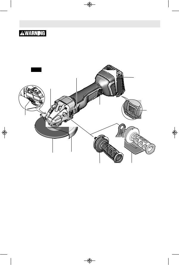
GWS18V-45C
Cordless Angle Grinder with Side Switch
FIG. 1
SIDE |
|
SWITCH |
BATTERY PACK |
|
|
SPINDLE |
|
LOCK |
|
|
LOCATION FOR |
BATTERY |
|
BLUETOOTH |
|
GUARD |
CONNECTIVITY |
PACK |
MODULE |
RELEASE |
|
RELEASE |
(OPTIONAL) |
BUTTON |
LEVER |
|
|
GRINDING WHEEL
WHEEL GUARD
VIBRATION CONTROL |
HAND GUARD |
SIDE HANDLE |
(Optional Accessory) |
-9-
Functional Description and Specifications
Disconnect battery pack from tool before making any assembly, adjustments or changing accessories. Such preventive safety measures
reduce the risk of starting the tool accidentally.
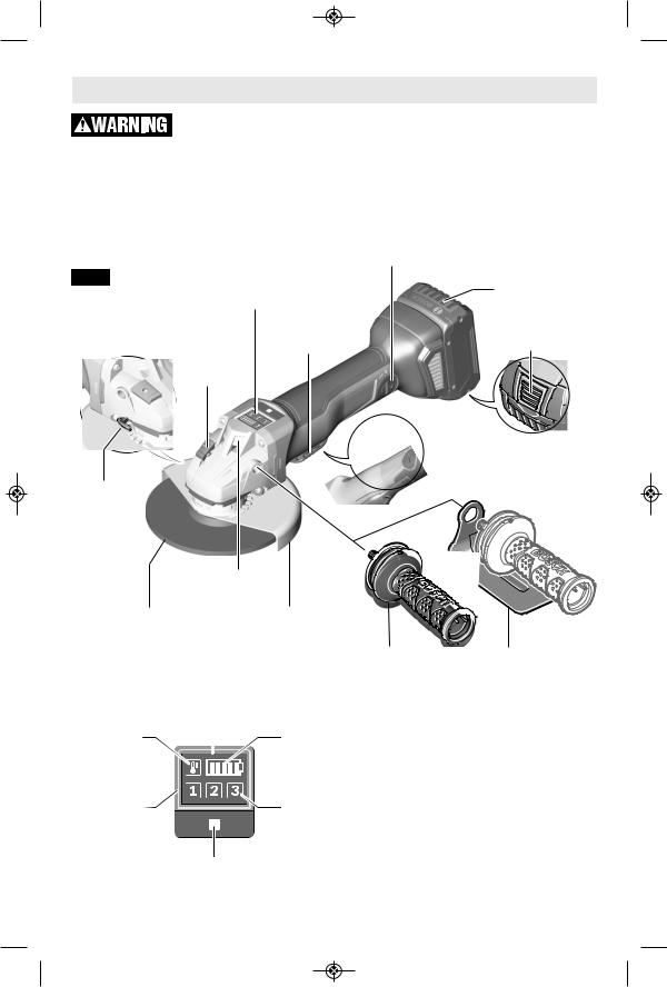
GWS18V-45PC/PSC
Cordless Angle Grinder with Paddle Switch
LOCATION FOR BLUETOOTH |
|
CONNECTIVITY MODULE |
|
(GWS18V-45PC OPTIONAL) |
|
FIG. 2 |
BATTERY PACK |
USER INTERFACE |
|
(GWS18V-45PSC) |
|
PADDLE |
BATTERY PACK |
SWITCH |
RELEASE BUTTON |
SPINDLE |
|
LOCK |
|
 "LOCK-OFF" SWITCH
RELEASE LEVER
GUARD
RELEASE
LEVER
WORK LIGHT (GWS18V-45PSC)
GRINDING |
WHEEL |
|
WHEEL |
GUARD |
|
|
VIBRATION CONTROL |
HAND GUARD |
|
SIDE HANDLE |
(Optional Accessory) |
USER INTERFACE |
|
|
(GWS18V-45PSC) |
|
|
OVERLOAD |
BATTERY STATUS |
|
PROTECTION |
|
|
INDICATOR |
|
|
INDICATOR |
|
|
|
|
|
POWER TOOL |
SPEED |
|
STATUS |
PRESELECTION |
|
INDICATOR |
LEVEL |
|
SPEED |
|
|
PRESELECTION |
|
|
BUTTON |
|
|
-10-
Functional Description and Specifications
Disconnect battery pack from tool before making any assembly, adjustments or changing accessories. Such preventive safety measures
reduce the risk of starting the tool accidentally.
Model number |
GWS18V-45C |
GWS18V-45PC |
GWS18V-45PSC |
|
|
|
|
Battery |
18V (Bosch Series) |
18V (Bosch Series) |
18V (Bosch Series) |
|
|
|
|
Rated speed |
n 9,000/min |
n 9,000/min |
n 9,000/min |
|
|
|
|
Switch Type |
Side |
Paddle |
Paddle |
|
|
|
|
Run-Out Brake |
Included |
Included |
Included |
|
|
|
|
Bluetooth Connectivity Tool Module |
Optional |
Optional |
Included |
|
|
|
|
Spindle thread |
5/8"-11 UNC |
5/8"-11 UNC |
5/8"-11 UNC |
|
|
|
|
Max. spindle length |
9/16" (14,3 mm) |
9/16" (14,3 mm) |
9/16" (14,3 mm) |
|
|
|
|
Max.Type 27 grinding wheel |
4 1/2" (115 mm) |
4 1/2" (115 mm) |
4 1/2" (115 mm) |
|
|
|
|
Type 27 grinding wheel thickness |
0.25" (6mm) |
0.25" (6mm) |
0.25" (6mm) |
|
|
|
|
Max.Type 41/1A, 27A cutting wheel |
4 1/2" (115 mm) |
4 1/2" (115 mm) |
4 1/2" (115 mm) |
|
|
|
|
Max. flap disc |
4 1/2" (115 mm) |
4 1/2" (115 mm) |
4 1/2" (115 mm) |
|
|
|
|
Max. sanding disc |
4 1/2" (115 mm) |
4 1/2" (115 mm) |
4 1/2" (115 mm) |
|
|
|
|
Max. wire wheel |
4" (102 mm) |
4" (102 mm) |
4" (102 mm) |
|
|
|
|
Max. wire cup brush |
3" (76 mm) |
3" (76 mm) |
3" (76 mm) |
|
|
|
|
|
Battery Packs/Chargers |
|
|
Please refer to the Charger Manual included with your tool. |
|
||
NOTE: For tool specifications refer to the nameplate on your tool. |
|
||
Accessory speed rating must be equal to or greater than the tool’s speed rating. Do not |
|||
exceed the recommended wheel diameter. |
|
|
|
NOTE: Not recommended for use with type 11 cup wheels. |
|
||
-11-
|
INSERTING THE BLUETOOTH Assembly |
|
||
|
CONNECTIVITY TOOL MODULE |
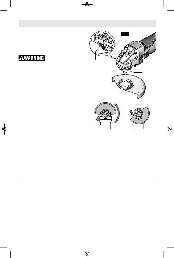
FIG. 3 |
|
|
Read the corresponding operating |
|
|
||
instructions for information about the |
|
|
||
Bluetooth® Connectivity Tool Module. |
|
|
|
|
|
WHEEL GUARD INSTALLATION |
|
|
|
|
Wheel guard must be |
|
|
|
|
attached when |
using |
GUARD |
|
disc grinding or cutting wheels. |
Always |
|
||
keep wheel guard be weent you and your work |
|
|||
while grinding or cutting. |
|
RELEASE |
MOUNTING |
|
|
|
|
LEVER |
GUARD |
TO ATTACH WHEEL GUARD: Disconnect |
|
FLANGE |
||
battery pack from tool. |
|
|
|
|
Press and hold the release lever (Fig. 3), and |
|
|
||
place the guard on the guard mounting |
|
|
||
flange until the guard’s keys line up with the |
|
|
||
notches in the spindle collar (Fig. 3A). |
|
KEYS |
|
|
Press the guard onto the guard mounting |
|
|
||
flange until the shoulder of the guard is |
|
|
||
seated against the flange of the tool, and turn |
|
|
||
the guard until it can clearly be heard to |
|
|
||
engage. |
|
|
|
|
Adjust the position of the guard to the |
|
|
||
requirements of the work process. For this, |
A |
B |
||
press the release lever upward and turn the |
||||
guard until it clicks into place then adjust as |
|
|
||
needed. |
|
circumstances and must be taken to an |
||
• |
Always adjust the guard in such a manner |
|||
|
that all 3 red cams of release lever engage |
after-sales service agent. |
|
|
|
into the corresponding notches of the |
Note: The encoding keys on the guard |
||
|
guard (Fig. 3B). |
|
ensure that only a guard that fits the tool type |
|
• |
Adjust the guard in such a manner that |
can be mounted. |
|
|
|
sparking is prevented in the direction of the |
TO REMOVE GUARD: Press release lever, |
||
• |
operator. |
|
rotate guard until the keys on guard line up |
|
The guard should turn only upon actuation |
with the notches on the guard mounting flange, |
|||
|
of the release lever! Otherwise the tool |
and lift guard off the guard mounting flange |
||
|
may not continue to be used under any |
(Fig. 3). |
|
|
LOCK NUT AND BACKING FLANGE
Your tool is equipped with a threaded spindle for mounting ac ces sories. Always use the supplied lock nut (and backing flange) that has same thread size as spindle.
VIBRATION CONTROL SIDE HANDLE
The side handle is used to control and balance the tool. The handle must be thread ed into the front housing on either side of the tool, depending on per sonal preference and comfort. Use the side handle for safe control and ease of operation (Fig. 1).
OPTIONAL HAND GUARD
(Optional Accessory)
The hand guard is to be used with backing pads, sanding discs and wire brushes to keep fingers and hand away from work surface, sharp edges, burrs and debris. When using the optional hand guard accessory insert side handle through hole in guard and then thread into housing (Fig. 1).
Ensure that hand guard is positioned between hand and backing pad, sanding disc or wire brush.
-12-

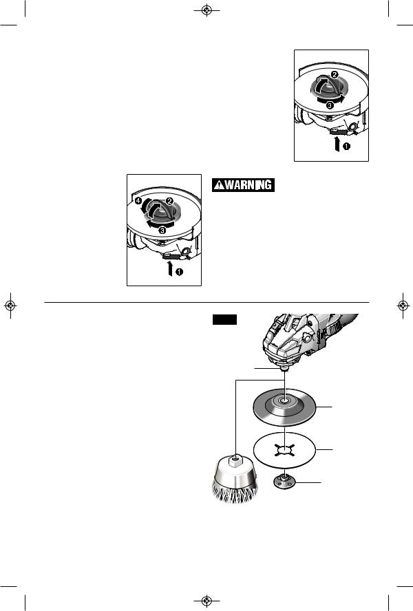
DISC GRINDING WHEEL ASSEMBLY
Disconnect battery pack from tool. Be sure that wheel guard is in place for grinding. Place BACKING FLANGE and GRINDING WHEEL on the spindle. Thread on the lock nut and tighten nut using the supplied lock nut wrench, while holding the spindle lock in (Fig. 4).
TO REMOVE: Reverse procedure.
Not recommended for use with spin-on wheels.
TYPE 27 |
SPINDLE |
|
GRINDING |
||
|
||
WHEEL |
|
|
|
BACKING |
|
|
FLANGE |
|
|
LOCK NUT |
|
|
(OPTIONAL) |
FIG. 4
SPINDLE 

TYPE 27
WHEEL
GUARD
BACKING
FLANGE
TYPE 27
GRINDING
WHEEL
 LOCK NUT
  (OPTIONAL)
QUICK-
CLAMPING NUT
ABRASIVE TYPE 41/1A AND 27A
WHEEL ASSEMBLY
Using the optional Type 41/1A wheel guard, it is possible to perform limited cutting on small stock such as metal tubes, piping or rebar.
Do not attempt to cut large stock or sheets of metal as this tool is not designed to be a dedicated cutting tool.
Always use Type 41/1A cutting. protection guard for
Disconnect battery pack from tool. Be sure that wheel guard is in place for cutting. When using mounting wheels, thread BACKING FLANGE onto spindle, then place WHEEL on the spindle. Thread on the lock nut and tighten nut using a lock nut wrench provided with adapter kit, while holding the spindle lock in (Fig. 5).
TO REMOVE: Reverse procedure.
TYPE 41/1A ABRASIVE
STRAIGHT GRINDING WHEELS
Do not use Type 41/1A abrasive wheels designed for straight/die grinding. This tool
is not designed for use with Type 41/1A abrasive straight/die grinding wheels.
FIG. 5
SPINDLE
TYPE 41/1A WHEEL GUARD (OPTIONAL)
BACKING
FLANGE
|
QUICK- |
|
CLAMPING NUT |
TYPE 41/1A |
TYPE 27A |
CUTTING WHEEL |
CUTOFF |
|
WHEEL |
-13-
QUICK-CLAMPING NUT
Use the quick-clamping nut to secure the grinding/cutting disc without the need for additional tools. Only use the quick-clamping nut for grinding/cutting discs up to a maximum diameter of 4 1/2”.
• The quick-clamping nut may be used only for grinding or cutting discs.
• Only use quick-clamping nuts that are in good working order and not damaged.
• When screwing on, make sure that the printed side of the quick-clamping nut is not facing the grinding disc.
Press the spindle lock button to lock the grinding spindle. To tighten the quickclamping nut, fold up the bar and turn the quick-clamping nut firmly clockwise. Then fold down the bar to secure the quickclamping nut. It is not sufficient to tighten the disc along the edge.
A properly secured, undamaged quickclamping nut can be removed by hand. To do this, fold up the bar and turn the quickclamping nut firmly anticlockwise, Fig 8. If the quick-clamping nut is stuck, do not attempt to loosen it with a tool – always use a two pin spanner.
Only use accessories with Maximum Safe Operating Speed rated at least equal to the
maximum speed marked on the power tool. This speed is based on the strength of the wheel. It is not meant to imply a best or most efficient operating speed. Do not exceed the Maximum Safe Operating Speed.
SANDING ACCESSORIES ASSEMBLY |
||||
|
|
BACKING PAD |
||
|
|
|
|
Before attaching a backing |
|
|
|
|
pad be sure its maximum |
safe operating |
eed is not exceeded by the |
|||
nameplate speed of the tool. |
||||
|
|
|
|
Wheel guard may not be |
|
|
|
|
used for most sanding |
operations. Alw |
s reinstall wheel guard when |
|||
converting back to grinding operations. |
||||
|
|
|
|
Do not use the Quick- |
|
|
|
|
Clamping Nut with backing |
pad for sanding |
ccessories. |
|||
TO INSTALL BACKING PAD AND
SANDING DISC (Not Included)
Disconnect battery pack from tool.
Attach hand guard (Fig. 1). Set the tool on its top side (spindle up). Place the rubber backing pad onto the spindle shaft. Center the sanding disc on top of the backing pad. Insert the lock nut through the disc and thread onto the spindle as far as you can with your fingers. Press in the spindle lock, then tighten the backing pad securely with lock nut wrench (Fig. 6).
TO REMOVE: Reverse procedure.
FIG. 6
SPINDLE
BACKING |
PAD |
SANDING
DISC
LOCK NUT |
(OPTIONAL) |
 WIRE BRUSH
-14-

WIRE BRUSH ASSEMBLY
Before assembling wire brush to this tool, disconnect from the power source. Attach hand guard (Fig. 1). Wire brushes are equipped with their own threaded hub, simply thread on to spindle. Be sure to seat against shoulder before turning tool “ON”.
TO REMOVE: Reverse procedure.
WIRE WHEEL ASSEMBLY
Before assembling wire wheel to this tool, disconnect from the power source. Attach type 27 guard (Fig. 3). Wire wheels are equipped with their own threaded hub, simply thread on to spindle. Be sure to seat against shoulder before turning tool “ON”.
TO REMOVE: Reverse procedure.
|
|
|
|
|
|
|
Operating Instructions |
|
|
|
User Interface (GWS18V-45PSC) (see figure 2) |
|
||
The user interface is used to preselect the speed and to indicate the status of the power tool. |
||||
SPEED PRESELECTION |
|
|
|
|
You can use the button for speed preselection to preselect the required speed, even during |
||||
operation. The data in the following table are recommended values. |
|
|||
Material |
Application |
Accessory |
Speed preselec- |
GWS18V-45PSC |
|
|
|
tion level |
[min-1] |
Metal |
Brushing, rust re- |
Cup brush |
1 |
4500 |
|
moval |
|
|
|
Stainless |
Grinding |
Fibre disc |
2 |
6000 |
steel |
|
|
|
|
Metal |
Rough grinding |
Grinding disc |
3 |
9000 |
Metal |
Cutting |
Cutting disc |
3 |
9000 |
Masonry, |
Cutting |
Diamond cutting disc and cutting guide (cutting |
3 |
9000 |
stone |
|
stone is permitted only with a cutting guide) |
|
|
STATUS INDICATIONS
Battery status indicator (User interface) |
Meaning/Cause |
Solution |
green |
Battery charged |
|
yellow |
Battery almost empty |
Replace or charge battery soon |
red |
Battery pack empty |
Replace or charge battery |
Overload protection indicator |
Meaning/Cause |
Solution |
(User interface) |
|
|
yellow |
Critical temperature has been |
Run the power tool at no load and allow it |
|
reached (motor, electronics, |
to cool down |
|
battery) |
|
red |
Power tool is overheated and |
Allow the power tool to cool down |
|
switches off |
|
Power tool status indicator |
Meaning/Cause |
Solution |
(User interface) |
|
|
green |
Status OK |
– |
yellow |
Critical temperature has been |
Run the power tool at no load and allow it |
|
reached or battery is almost empty |
to cool down, or replace or charge the |
|
|
battery soon |
Illuminated red |
Power tool is overheated or battery |
Allow the power tool to cool down, or re- |
|
is empty |
place or charge the battery |
Flashing red |
Kickback shutdown, restart |
Switch the power tool off and on again |
|
protection has been triggered |
|
|
|
|
Flashing blue |
Power tool is connected to a mobile |
– |
|
terminal device or settings are |
|
|
being transferred |
|
-15-
Hold the tool with both hands while starting the tool, since torque from the motor can cause the
tool to twist.
Start the tool before applying to work and let the tool come to full speed before contacting the workpiece. Lift the tool from the work before releasing the switch. DO NOT turn the switch “ON” and “OFF” while the tool is under load; this will greatly decrease the switch life.
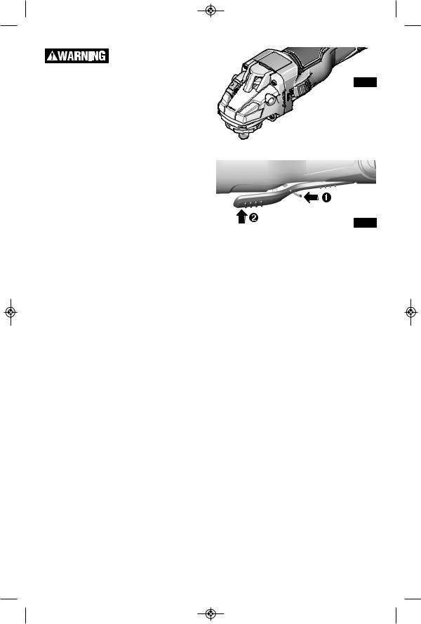
SIDE ON-OFF SWITCH
WITH LOCK (FIG. 8)
The tool is switched “ON” by the side switch located at the side of the motor housing. The switch can be locked in the “ON” position, a convenience for long grinding operations.
TO TURN THE TOOL “ON” without locking it, move the switch forward by applying pressure ONLY at the REAR portion of the switch. When pressure is released the switch will return to “OFF” position.
TO LOCK THE SWITCH “ON”, move the switch forward and press the FRONT portion. TO UNLOCK THE SWITCH, simply press and release the REAR portion of the slider. Switch is spring loaded and will snap back automatically.
PADDLE SWITCH (FIG. 9)
The paddle switch has a lock-off feature to help prevent accidental startups.
TO TURN TOOL “ON”, push lock-off switch forward to unlock the paddle switch, then squeeze paddle switch.
TO TURN TOOL “OFF”, release pressure on paddle switch. The switch is spring loaded and will return to the “OFF” position automatically.
FIG. 8
 SIDE
SIDE
SWITCH
ON |
FIG. 9 |
OFF 
-16-
|
|
|
Grinding Operations |
|||||||
SELECTING GRINDING WHEELS |
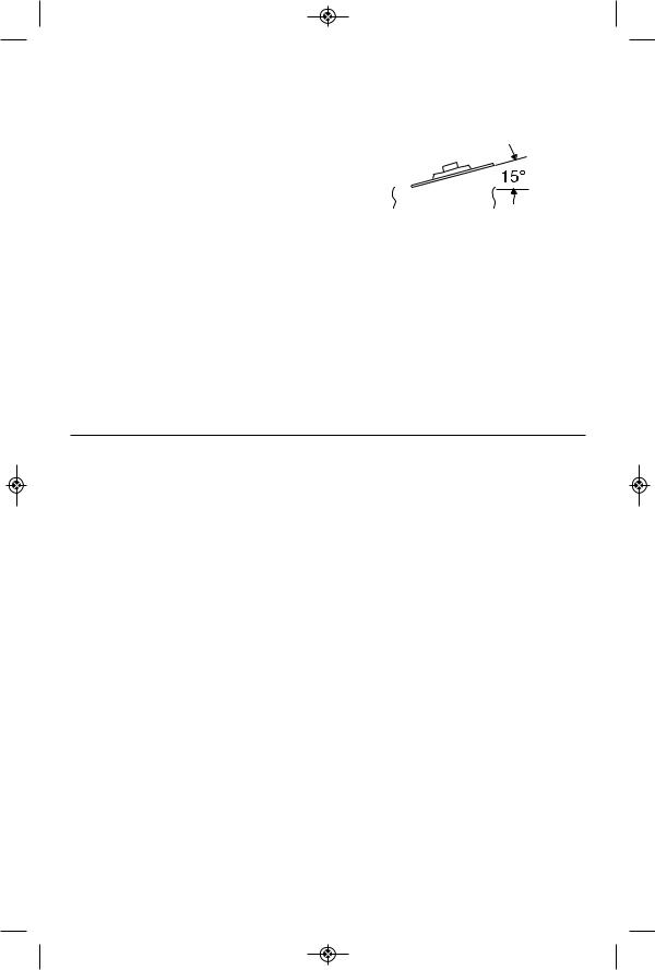
the tool is difficult to control. If the angle is too |
|||||||||
|
|
|
Before using a grinding |
steep, the pressure is concentrated on a small |
||||||
|
|
|
wheel, be certain that its |
area causing burning to the work surface. |
||||||
maximum saf operating speed is not |
|
|
|
|
|
|
||||
exceeded by the nameplate speed of the |
|
|
|
|
|
|
||||
grinder. Do not exceed the recom mended |
|
|
|
|
|
|
||||
wheel diameter. |
|
|
|
|
|
|
||||
|
|
|
|
|
|
|||||
DISC GRINDING WHEELS |
|
|
|
|
|
|
||||
|
|
|
|
|
|
|||||
Grinding wheels should be carefully selected in |
|
|
|
|
Excessive or sudden |
|||||
order to use the grinder most efficiently. Wheels |
|
|
|
|
pressure on the wheel will |
|||||
vary in type of abrasive, bond, hardness, grit |
|
|
|
|
||||||
slow grinding ction and put dangerous |
||||||||||
size and structure. The correct type of wheel to |
||||||||||
stresses on the wheel. |
||||||||||
use is determined by the job. Use disc grinding |
||||||||||
When grinding with a new wheel be certain to |
||||||||||
wheels for fast grinding of structural steel, |
||||||||||
heavy weld beads, steel casting, stainless steel |
grind while pulling tool backwards until wheel |
|||||||||
and other ferrous metals. |
becomes rounded on its edge. New wheels |
|||||||||
|
|
GRINDING TIPS |
have sharp corners which tend to “bite” or cut |
|||||||
|
|
into work piece when pushing forward. |
||||||||
Efficient grinding is achieved by controlling the |
||||||||||
pressure and keep ngi the angle between wheel |
|
|
|
|
|
|
||||
and workpiece at 10° to 15°. If the wheel is flat, |
|
|
|
|
|
|
||||
|
|
|
Cutting Operations |
||
|
|
|
Do not use this grinder for |
• |
Always follow precautions for kickback. |
|
|
|
cutting masonry. |
• |
Do not apply side pressure to cutting wheel |
|
|
|
|||
|
|
CUTTING METAL |
|
to reduce wheel speed. |
|
Using the optional Type 41/1A wheel guard, |
• |
The tool should always be used so that |
|||
it is possible to perform limited cutting on |
|
sparks are directed away from user. |
|||
small stock such as metal tubes, piping or |
|
|
|||
rebar. When cutting, work with moderate feed, adapted to the material being cut. Do not exert side pressure onto the cutting disc, tilt or oscillate the tool. When cutting profiles and square bar, it is best to start at the smallest cross section.
-17-
|
|
|
|
|
|
|
Sanding Operations |
|
||
|
SELECTING SANDING DISC |
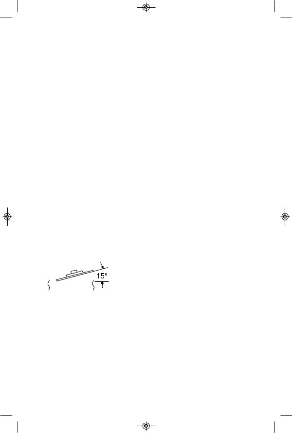
If sander is tilted too much, sanding action will |
||||||||
Sanding discs are made of extremely hard |
be too great and a rough cut surface or |
|||||||||
and sharp aluminum oxide grits, phenol-resin |
gouging and snagging will result. |
|||||||||
bonded to a sturdy fiber backing for fast |
Guide the Disc Sander with crosswise strokes. |
|||||||||
heavy-duty service and long life. The discs |
||||||||||
Be careful not to hold the sander in one spot |
||||||||||
vary as to size and spacing of the abrasive |
||||||||||
too long. Do not use a circular motion, as this |
||||||||||
grits. OPEN COAT (type H) — used for soft |
||||||||||
makes swirl marks. Test before use on scrap stock. |
||||||||||
materials and on paint or varnish. CLOSED |
||||||||||
Do not force or apply pressure when sanding. |
||||||||||
COAT (type K) —used for metal, hardwood, |
||||||||||
stone, marble and other materials. |
|
Use only the weight of the tool for pressure. |
||||||||
Sanding discs range in grit from 16 (very |
Excess pressure actually slows the tool down. |
|||||||||
If faster stock removal is desired, change to a |
||||||||||
coarse) to 180 (very fine). To obtain best |
||||||||||
coarser grit disc. |
||||||||||
results, select sanding discs carefully. Many |
||||||||||
jobs require the use of several grit sizes and |
Remove gummy paint from metal with an |
|||||||||
at times both “open coat and closed coat” |
“open coat” disc. Sand until sparks start to |
|||||||||
discs are required to get the job done faster. |
appear, then stop and change to a “closed |
|||||||||
See chart for application examples. |
coat” disc to remove any remaining paint. |
|||||||||
|
|
|
|
|
|
|
|
SANDING WOOD |
||
Operation: Refinishing painted wood or metal surfaces. |
|
|||||||||
|
|
|
|
|
|
|
|
When sanding wood the direction of the disc |
||
|
REMARKS |
|
GRIT |
|||||||
|
|
|
|
|
|
|
|
motion at the contact point should parallel the |
||
To remove paint and to smooth |
|
Coarse |
||||||||
|
grain as much as possible. The rapid cut of |
|||||||||
surface irregularities. |
|
16-24-30 |
||||||||
|
|
|
|
|
|
|
|
discs and the swirl type scratch pattern they |
||
To smooth |
|
Medium |
||||||||
|
occasionally create generally prohibit their use |
|||||||||
the rough sanding. |
|
36-50-80 |
||||||||
|
for producing the final finish. |
|||||||||
To remove scratches left by |
|
Fine |
||||||||
|
Scratches and circular marks are usually the |
|||||||||
previous discs. |
|
100-120 |
||||||||
|
|
|
|
|
|
|
|
result of using too coarse a grit. When |
||
To smooth surfaces for painting, |
|
Very Fine |
||||||||
|
changing to a finer grit, move across the sand- |
|||||||||
polishing or waxing. |
|
150-180 |
||||||||
|
|
|
|
|
|
|
|
ing lines that were made by a previous coarser |
||
|
|
|
SANDING TIPS |
|
disc. |
|
||||
|
|
|
|
|
SANDING METAL |
|||||
For best results, tilt the Disc Sander at a 10° to |
|
|||||||||
When sanding automobiles or appliances, |
||||||||||
15° angle while sanding so that only about 1" |
||||||||||
wipe the metal clean with a non-flammable |
||||||||||
of the surface around the edge of the disc |
||||||||||
solvent or commercial cleaner to remove all |
||||||||||
contacts the work. |
|
|||||||||
|
wax and grease. By doing this first, the |
|||||||||
|
|
|
|
|
|
|
|
|||
|
|
|
|
|
|
|
|
sanding discs will sand better and last longer. |
||
|
|
|
|
|
|
|
|
For heavy duty work, use a coarse grit disc |
||
|
|
|
|
|
|
|
|
first. Follow-up with a medium grit to remove |
||
|
|
|
|
|
|
|
|
|||
|
|
|
|
|
|
|
|
scratches. To produce smooth finish, use fine |
||
|
|
|
|
|
|
|
|
|||
|
|
|
|
If the disc (accessory) is |
grit disc. |
|
||||
|
|
|
|
held flat or the back edge |
|
|
||||
of the disc comes in contact with the work, a |
|
|
||||||||
violent thrust to the side may result. |
|
|
|
|||||||
-18-
|
|
Wire Brush Operations |
||
Wire brushes are intended to “clean” structural |
pressure so only the tips of the wire come |
|||
steel, castings, sheet metal, stone and |
in contact with the work. |
|||
concrete. They are used to remove rust, scale |
2.If heavier pressures are used, the wires will |
|||
and paint. |
|
|
||
|
Avoid bouncing and |
be overstressed, resulting in a wiping |
||
|
|
action; and if this is continued, the life of |
||
|
|
snagging the wire brush, |
the brush will be shortened due to wire |
|
especially when working corners, sharp edges |
fatigue. |
|||
etc. This can cause loss of control and kick- |
3. Apply the brush to the work in such a way |
|||
back. |
|
|
||
|
|
that as much of the brush face as possible is |
||
|
BRUSHING PRESSURE |
in full contact with the work. Applying the side |
||
1.Remember, the tips of a wire brush do the |
or edge of the brush to the work will result in |
|||
work. Operate the brush with the lightest |
wire breakage and shortened brush life. |
|||
|
|
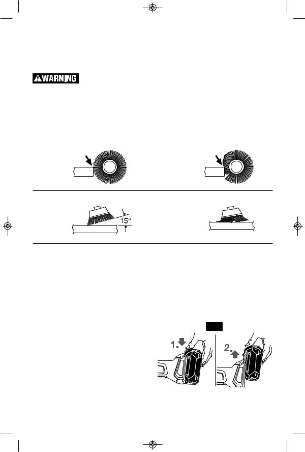
WIRE WHEEL BRUSH |
||
CORRECT: |
|
INCORRECT: |
||
Wire tips doing |
|
Excessive |
||
the work. |
|
pressure can |
||
|
|
|
cause wire |
|
|
|
|
breakage. |
|
|
|
WIRE CUP BRUSH |
||
CORRECT: |
|
INCORRECT: |
||
Wire tips doing |
|
Excessive pressure |
||
the work. |
|
can cause wire |
||
|
|
|
breakage. |
|
|
|
INSERTING AND RELEASING BATTERY PACK |
||
This tool is equipped with Automatic Restart |
To remove the battery pack, press the battery |
|||
Protection. This feature helps prevent |
pack release button and slide the battery pack |
|||
accidental startups after power has been |
forward. |
|||
interrupted, e.g. the battery was removed with |
Press the battery pack release button again |
|||
the switch locked in the on position. To resume |
||||
and slide the battery pack completely out of |
||||
operation, turn the side switch to the off |
||||
tool housing (Fig. 10). |
||||
position, and back to on position to restart the |
||||
|
||||
tool. |
|
|
FIG. 10 |
|
Make sure that the side switch is in the off |
||||
|
||||
position before inserting or removing battery |
|
|||
pack. (Fig. 8). To insert the battery pack slide it |
|
|||
into the housing until the battery pack locks |
|
|||
into position. |
|
|
||
Your tool is equipped with a secondary locking |
|
|||
latch to prevent the battery pack from |
|
|||
completely falling out of the handle, should it |
|
|||
become loose due to vibration. |
|
|||
-19-

USING ‘BOSCH TOOLBOX’ APP
After pairing your tool with a mobile device you can adjust certain functions or check the status of the power tool using Bosch Toolbox app.
Every time you change any setting the tool will confirm the changes by flashing the white LED work light on GWS18V-45PSC.
A. Help button – tapping this button will bring up help screen.
B. Tool photo – tapping on the photo will let you customize the photograph of the tool.
C. Power tool battery charge status – the number of green ‘batteries’ indicates the estimated charge level for the battery pack.
D. Power tool nickname – tapping on the ‘pencil’ icon will let you customize the tool nickname. You can also do it when changing the tool photo.
E. Connection status bar – Here you can see the connection (signal) strength K indicated by vertical bars. You can use toggle switch to disconnect the tool from you mobile device.
F. Soft Start - Allows speed ramp-up of grinder.
G. Work Light - Modify settings to LED (PSC only).
H. User Interface - Customize tool interface and usage settings.
I. Factory Reset toggle switch – you can reset tool settings back to factory default settings. When you do so the LED after glow will reset to ‘10s’ and KickBack Control will be reset to ‘Later’ setting.
J. Tool alerts – tapping the ‘alerts triangle’ will display any alerts received from the tool.
K. Info button – displays tool information and specifications.
GWS18V-45PSC |
|
A |
|
|
|||
|
|
|
B |
|
|
|
|
|
|
|
C |
|
|
|
|
|
|
|
D |
GWS18V-45PSC |
|
||
|
|||
|
|
|
E |
|
|
|
|
|
|
|
|
|
|
|
F |
|
|
|
|
|
|
|
G |
|
|
|
|
|
|
|
H |
|
|
|
|
|
|
|
I |
|
|
|
|
|
|
|
J |
|
|
|
|
-20-
 Loading...