


 Loading...
GTS 10 J Professional 
Robert Bosch Power Tools GmbH
70538 Stuttgart
GERMANY
www.bosch-pt.com
1 609 92A 5P7 (2020.09) PS / 105
1 609 92A 5P7
en Original instructions zh zh ko
th
id Petunjuk-Petunjuk untuk
Penggunaan Orisinal
vi Bản gốc hướng dẫn sửdụng
2 |
English ................................................... |
Page |
15 |
....................................................... |
27 |
|
.................................................. |
38 |
|
............................................... |
48 |
|
...................................................... |
61 |
|
Bahasa Indonesia..................................... |
Halaman |
77 |
Tiếng Việt ............................................... |
Trang |
91 |
1 609 92A 5P7 | (11.09.2020) |
|
|
|
Bosch Power Tools |
|
|
|
|
|
|
|
|
|
|
|
|
|
|
|
|
|
|
|
| 3
|
(2) |
(4) |
(6) |
(8) |
(1) |
(3) |
(5) |
|
(7) |
(19) |
(17) |
(15) |
(14) |
||
(20) |
(18) |
(16) |
(12) |
||
GTS 10 J
 (9)
(9)
3 601 M30 5C2
(10)(11)
 (4)
(4)
 (12)
(12)
 (13)
(13)
(21)
(22)
(23)
(24)
Bosch Power Tools |
|
|
|
1 609 92A 5P7 | (11.09.2020) |
|
|
|
|
|
|
|
|
|
|
|
|
|
|
|
|
|
|
|
4 |
3 601 M30 5C2
(8)(27) (28)
(25) |
(11) |
(26) |
(29) |
(1) |
(31) |
(34) (12) |
(33) |
(32) |
(12) (31) |
(30) |
1 609 92A 5P7 | (11.09.2020) |
|
|
|
Bosch Power Tools |
|
|
|
|
|
|
|
|
|
|
|
|
|
|
|
|
|
|
|
| 5
3 601 M30 5C2
Bosch Power Tools |
|
|
|
1 609 92A 5P7 | (11.09.2020) |
|
|
|
|
|
|
|
|
|
|
|
|
|
|
|
|
|
|
|
6 |
a1 |
3 601 M30 5C2 |
a2 |
3 601 M30 5C2 |
|
|
(8)
(8)
(37)
(22)
(36) |
(22) |
(36) |
|
(37)
(35)
(35)
b |
(26) |
c1 |
|
|
|
|
|
|
(38) |
|
|
|
(6) |
(40) |
|
|
|
|
(8) |
 (39)
(39)
 (8)
(8)
c2 |
|
d |
(10) (42)
(41)
(11)
(39)
 (1)
(1)
1 609 92A 5P7 | (11.09.2020) |
|
|
|
Bosch Power Tools |
|
|
|
|
|
|
|
|
|
|
|
|
|
|
|
|
|
|
|
e
(44) |
(43) |
(10) |
(44)
f2 (29)
(3)
(46)
h
(33) (32)
| 7
f1
(5)
(5)
(3)(45)
g
(47) 
(32) 
i
(12)
(12)
Bosch Power Tools |
|
|
|
1 609 92A 5P7 | (17.09.2020) |
|
|
|
|
|
|
|
|
|
|
|
|
|
|
|
|
|
|
|
8 |
j
GTA 600
k1 |
3 601 M30 5C2 |
|
 (6)
(6)
 (6)
(6)
(39)
 (39)
(39)
(8) |
(48) |
(9)
 (8)
(8)
k2 |
|
k3 |
(50)
(26)
(49) (23)
1 609 92A 5P7 | (11.09.2020) |
|
|
|
Bosch Power Tools |
|
|
|
|
|
|
|
|
|
|
|
|
|
|
|
|
|
|
|
| 9
k4
 (27)
(27)
(51) (49)
(53)
(52)
A |
|
B |
(3) |
(54) (55)
(55)
(56)
(57) 
(18)(17)
C
(16)
(14)
Bosch Power Tools |
|
|
|
1 609 92A 5P7 | (11.09.2020) |
|
|
|
|
|
|
|
|
|
|
|
|
|
|
|
|
|
|
|
10 |
D
 (10)
(10)
(58)
 (14)
(14)
|
(41) |
(2) |
(28) |
E |
|
|
|
F |
|
|
3 601 M30 5C2 |
|||
|
|
|
|
|
|
|
|
|||
|
|
|
|
|
|
|
|
|
|
|
|
|
|
|
|
|
|
|
|
|
|
|
|
(8) |
|
|
|
|
|
|||
(43) |
(10) |
|
|
|
|
(8) |
|
|
||
|
|
|
|
|
|
|
|
|
||
|
|
|
|
|
|
|
|
|
|
|
|
|
|
|
|
|
|
(37) |
|
|
|
|
|
|
|
|
|
|
|
|
|
|
|
|
|
|
|
|
|
(37) |
(22) |
||
|
|
|
|
|
|
|
(36) |
|
||
|
|
|
|
|
|
|
|
|
||
|
|
|
|
|
|
|
(35) |
|
|
|
|
|
(27) |
|
|
|
|
||||
|
|
|
|
|
|
|
|
|
|
|
G1 |
|
G2 |
|
|
|
|
||||
(20) |
|
|
|
|
|
|
|
|
|
|
(59)
(20) 
1 609 92A 5P7 | (11.09.2020) |
|
|
|
Bosch Power Tools |
|
|
|
|
|
|
|
|
|
|
|
|
|
|
|
|
|
|
|
| 11
H
(10) (43) |
(24) |
(3) |
I
(5)
(60) |
(56) |
J1 |
J2 |
(65)
(62) (54) (63)
(61) |
(18) |
(17) |
(64) |
Bosch Power Tools |
|
|
|
1 609 92A 5P7 | (11.09.2020) |
|
|
|
|
|
|
|
|
|
|
|
|
|
|
|
|
|
|
|

12 |
K
(67)
(5)
(67)
(66)
(66)
L
(58)(68)
1 609 92A 5P7 | (17.09.2020) |
|
|
|
Bosch Power Tools |
|
|
|
|
|
|
|
|
|
|
|
|
|
|
|
|
|
|
|
| 13
M N
(26)
 (69)
(69)
(2)
(28)
|
|
|
(41) |
|
|
|
(70) |
|
|
|
|
||
|
|
|
(71) |
(21) |
||
|
|
|
|
|
|
|
O1 |
O2 |
|
||||
|
|
|
(44) |
|
||
|
|
|
(72) |
|
||
|
|
|
(73) |
|
||
|
|
|
(6) |
|
|
|
(34) |
(33) |
|
||||
|
|
|
|
|
||
O1 |
|
|
(74) |
|
||
|
3 601 M30 5C2 |
|
||||
|
|
|
|
|
||
|
|
|
|
|
|
|
 (9)
(9)
(34)(6)
Bosch Power Tools |
|
|
|
1 609 92A 5P7 | (11.09.2020) |
|
|
|
|
|
|
|
|
|
|
|
|
|
|
|
|
|
|
|
14 |
O3 |
|
|
O4 |
(75) |
(24) |
(23) |
|
(10)
O5
(76)(22)
(31) |
(43) |
 (31)
(31)
 (77)
(77)
(76) (21)
 (3)
(3)
P
1 609 92A 5P7 | (11.09.2020) |
|
|
|
Bosch Power Tools |
|
|
|
|
|
|
|
|
|
|
|
|
|
|
|
|
|
|
|
English
Safety instructions
General Power Tool Safety Warnings
 WARNING Read all safety warnings, instructions, illustrations and specifica-
tions provided with this power tool. Failure to follow all in-
structions listed below may result in electric shock, fire and/
or serious injury.
Save all warnings and instructions for future reference.
The term "power tool" in the warnings refers to your mainsoperated (corded) power tool or battery-operated (cordless) power tool.
Work area safety
uKeep work area clean and well lit. Cluttered or dark areas invite accidents.
uDo not operate power tools in explosive atmospheres, such as in the presence of flammable liquids, gases or dust. Power tools create sparks which may ignite the dust or fumes.
uKeep children and bystanders away while operating a power tool. Distractions can cause you to lose control.
Electrical safety
uPower tool plugs must match the outlet. Never modify the plug in any way. Do not use any adapter plugs with earthed (grounded) power tools. Unmodified plugs and matching outlets will reduce risk of electric shock.
uAvoid body contact with earthed or grounded surfaces, such as pipes, radiators, ranges and refrigerators. There is an increased risk of electric shock if your body is earthed or grounded.
uDo not expose power tools to rain or wet conditions.
Water entering a power tool will increase the risk of electric shock.
uDo not abuse the cord. Never use the cord for carrying, pulling or unplugging the power tool. Keep cord away from heat, oil, sharp edges or moving parts.
Damaged or entangled cords increase the risk of electric shock.
uWhen operating a power tool outdoors, use an extension cord suitable for outdoor use. Use of a cord suitable for outdoor use reduces the risk of electric shock.
uIf operating a power tool in a damp location is unavoidable, use a residual current device (RCD) protected supply. Use of an RCD reduces the risk of electric shock.
Personal safety
uStay alert, watch what you are doing and use common sense when operating a power tool. Do not use a power tool while you are tired or under the influence of drugs, alcohol or medication. A moment of inatten-
English | 15
tion while operating power tools may result in serious personal injury.
uUse personal protective equipment. Always wear eye protection. Protective equipment such as a dust mask, non-skid safety shoes, hard hat or hearing protection used for appropriate conditions will reduce personal injuries.
uPrevent unintentional starting. Ensure the switch is in the off-position before connecting to power source and/or battery pack, picking up or carrying the tool.
Carrying power tools with your finger on the switch or energising power tools that have the switch on invites accidents.
uRemove any adjusting key or wrench before turning the power tool on. A wrench or a key left attached to a rotating part of the power tool may result in personal injury.
uDo not overreach. Keep proper footing and balance at all times. This enables better control of the power tool in unexpected situations.
uDress properly. Do not wear loose clothing or jewellery. Keep your hair and clothing away from moving parts. Loose clothes, jewellery or long hair can be caught in moving parts.
uIf devices are provided for the connection of dust extraction and collection facilities, ensure these are connected and properly used. Use of dust collection can reduce dust-related hazards.
uDo not let familiarity gained from frequent use of tools allow you to become complacent and ignore tool safety principles. A careless action can cause severe injury within a fraction of a second.
Power tool use and care
uDo not force the power tool. Use the correct power tool for your application. The correct power tool will do the job better and safer at the rate for which it was designed.
uDo not use the power tool if the switch does not turn it on and off. Any power tool that cannot be controlled with the switch is dangerous and must be repaired.
uDisconnect the plug from the power source and/or remove the battery pack, if detachable, from the power tool before making any adjustments, changing accessories, or storing power tools. Such preventive safety measures reduce the risk of starting the power tool accidentally.
uStore idle power tools out of the reach of children and do not allow persons unfamiliar with the power tool or these instructions to operate the power tool. Power tools are dangerous in the hands of untrained users.
uMaintain power tools and accessories. Check for misalignment or binding of moving parts, breakage of parts and any other condition that may affect the power tool’s operation. If damaged, have the power tool repaired before use. Many accidents are caused by poorly maintained power tools.
Bosch Power Tools |
|
|
|
1 609 92A 5P7 | (11.09.2020) |
|
|
|
|
|
|
|
|
|
|
|
|
|
|
|
|
|
|
|
16 | English
uKeep cutting tools sharp and clean. Properly maintained cutting tools with sharp cutting edges are less likely to bind and are easier to control.
uUse the power tool, accessories and tool bits etc. in accordance with these instructions, taking into account the working conditions and the work to be performed. Use of the power tool for operations different from those intended could result in a hazardous situation.
uKeep handles and grasping surfaces dry, clean and free from oil and grease. Slippery handles and grasping surfaces do not allow for safe handling and control of the tool in unexpected situations.
Service
uHave your power tool serviced by a qualified repair person using only identical replacement parts. This will ensure that the safety of the power tool is maintained.
Safety instructions for table saws
Guarding related warnings
uKeep guards in place. Guards must be in working order and be properly mounted. A guard that is loose, damaged, or is not functioning correctly must be repaired or replaced.
uAlways use saw blade guard, riving knife and antikickback device for every through–cutting operation.
For through-cutting operations where the saw blade cuts completely through the thickness of the workpiece, the guard and other safety devices help reduce the risk of injury.
uImmediately reattach the guarding system after completing an operation (such as rabbeting, dadoing or resawing cuts) which requires removal of the guard, riving knife and/or anti-kickback device. The guard, riving knife and anti-kickback device help to reduce the risk of injury.
uMake sure the saw blade is not contacting the guard, riving knife or the workpiece before the switch is turned on. Inadvertent contact of these items with the saw blade could cause a hazardous condition.
uAdjust the riving knife as described in this instruction manual. Incorrect spacing, positioning and alignment can make the riving knife ineffective in reducing the likelihood of kickback.
uFor the riving knife and anti-kickback device to work, they must be engaged in the workpiece. The riving knife and anti-kickback device are ineffective when cutting workpieces that are too short to be engaged with the riving knife and anti-kickback device. Under these conditions a kickback cannot be prevented by the riving knife and anti-kickback device.
uUse the appropriate saw blade for the riving knife. For the riving knife to function properly, the saw blade diameter must match the appropriate riving knife and the body of the saw blade must be thinner than the thickness of the riving knife and the cutting width of the saw blade must be wider than the thickness of the riving knife.
Cutting procedures warnings
u  DANGER: Never place your fingers or hands in the vicinity or in line with the saw blade. A moment of inat-
tention or a slip could direct your hand towards the saw
blade and result in serious personal injury.
uFeed the workpiece into the saw blade only against the direction of rotation. Feeding the workpiece in the same direction that the saw blade is rotating above the table may result in the workpiece, and your hand, being pulled into the saw blade.
uNever use the mitre gauge to feed the workpiece when ripping and do not use the rip fence as a length stop when cross cutting with the mitre gauge. Guiding the workpiece with the rip fence and the mitre gauge at the same time increases the likelihood of saw blade binding and kickback.
uWhen ripping, always apply the workpiece feeding force between the fence and the saw blade. Use a push stick when the distance between the fence and the saw blade is less than 150mm, and use a push block when this distance is less than 50 mm. “Work helping” devices will keep your hand at a safe distance from the saw blade.
uUse only the push stick provided by the manufacturer or constructed in accordance with the instructions.
This push stick provides sufficient distance of the hand from the saw blade.
uNever use a damaged or cut push stick. A damaged push stick may break causing your hand to slip into the saw blade.
uDo not perform any operation “freehand”. Always use either the rip fence or the mitre gauge to position and guide the workpiece. “Freehand” means using your hands to support or guide the workpiece, in lieu of a rip fence or mitre gauge. Freehand sawing leads to misalignment, binding and kickback.
uNever reach around or over a rotating saw blade.
Reaching for a workpiece may lead to accidental contact with the moving saw blade.
uProvide auxiliary workpiece support to the rear and/ or sides of the saw table for long and/or wide workpieces to keep them level. A long and/or wide workpiece has a tendency to pivot on the table’s edge, causing loss of control, saw blade binding and kickback.
uFeed workpiece at an even pace. Do not bend or twist the workpiece. If jamming occurs, turn the tool off immediately, unplug the tool then clear the jam. Jamming the saw blade by the workpiece can cause kickback or stall the motor.
uDo not remove pieces of cut-off material while the saw is running. The material may become trapped between the fence or inside the saw blade guard and the saw blade pulling your fingers into the saw blade. Turn the saw off and wait until the saw blade stops before removing material.
1 609 92A 5P7 | (11.09.2020) |
|
|
|
Bosch Power Tools |
|
|
|
|
|
|
|
|
|
|
|
|
|
|
|
|
|
|
|

uUse an auxiliary fence in contact with the table top when ripping workpieces less than 2 mm thick. A thin workpiece may wedge under the rip fence and create a kickback.
Kickback causes and related warnings
Kickback is a sudden reaction of the workpiece due to a pinched, jammed saw blade or misaligned line of cut in the workpiece with respect to the saw blade or when a part of the workpiece binds between the saw blade and the rip fence or other fixed object.
Most frequently during kickback, the workpiece is lifted from the table by the rear portion of the saw blade and is propelled towards the operator.
Kickback is the result of saw misuse and/or incorrect operating procedures or conditions and can be avoided by taking proper precautions as given below.
uNever stand directly in line with the saw blade. Always position your body on the same side of the saw blade as the fence. Kickback may propel the workpiece at high velocity towards anyone standing in front and in line with the saw blade.
uNever reach over or in back of the saw blade to pull or to support the workpiece. Accidental contact with the saw blade may occur or kickback may drag your fingers into the saw blade.
uNever hold and press the workpiece that is being cut off against the rotating saw blade. Pressing the workpiece being cut off against the saw blade will create a binding condition and kickback.
uAlign the fence to be parallel with the saw blade. A misaligned fence will pinch the workpiece against the saw blade and create kickback.
uUse a featherboard to guide the workpiece against the table and fence when making non-through cuts such as rabbeting, dadoing or resawing cuts. A featherboard helps to control the workpiece in the event of a kickback.
uSupport large panels to minimise the risk of saw blade pinching and kickback. Large panels tend to sag under their own weight. Support(s) must be placed under all portions of the panel overhanging the table top.
uUse extra caution when cutting a workpiece that is twisted, knotted, warped or does not have a straight edge to guide it with a mitre gauge or along the fence.
A warped, knotted, or twisted workpiece is unstable and causes misalignment of the kerf with the saw blade, binding and kickback.
uNever cut more than one workpiece, stacked vertically or horizontally. The saw blade could pick up one or more pieces and cause kickback.
uWhen restarting the saw with the saw blade in the workpiece, centre the saw blade in the kerf so that the saw teeth are not engaged in the material. If the saw blade binds, it may lift up the workpiece and cause kickback when the saw is restarted.
uKeep saw blades clean, sharp, and with sufficient set. Never use warped saw blades or saw blades with
English | 17
cracked or broken teeth. Sharp and properly set saw blades minimise binding, stalling and kickback.
Table saw operating procedure warnings
uTurn off the table saw and disconnect the power cord when removing the table insert, changing the saw blade or making adjustments to the riving knife, antikickback device or saw blade guard, and when the machine is left unattended. Precautionary measures will avoid accidents.
uNever leave the table saw running unattended. Turn it off and don’t leave the tool until it comes to a complete stop. An unattended running saw is an uncontrolled hazard.
uLocate the table saw in a well-lit and level area where you can maintain good footing and balance. It should be installed in an area that provides enough room to easily handle the size of your workpiece. Cramped, dark areas, and uneven slippery floors invite accidents.
uFrequently clean and remove sawdust from under the saw table and/or the dust collection device. Accumulated sawdust is combustible and may self-ignite.
uThe table saw must be secured. A table saw that is not properly secured may move or tip over.
uRemove tools, wood scraps, etc. from the table before the table saw is turned on. Distraction or a potential jam can be dangerous.
uAlways use saw blades with correct size and shape (diamond versus round) of arbour holes. Saw blades that do not match the mounting hardware of the saw will run off-centre, causing loss of control.
uNever use damaged or incorrect saw blade mounting means such as flanges, saw blade washers, bolts or nuts. These mounting means were specially designed for your saw, for safe operation and optimum performance.
uNever stand on the table saw, do not use it as a stepping stool. Serious injury could occur if the tool is tipped or if the cutting tool is accidentally contacted.
uMake sure that the saw blade is installed to rotate in the proper direction. Do not use grinding wheels, wire brushes, or abrasive wheels on a table saw. Improper saw blade installation or use of accessories not recommended may cause serious injury.
Additional safety warnings
uWhen mounting the saw blade, wear protective gloves. This poses a risk of injury.
uDo not use HSS saw blades. Such saw blades can easily break.
uNever use the tool without the table insert. Replace table insert if defective. Without flawless table inserts, injuries are possible from the saw blade.
uKeep your work area clean. Material mixtures are particularly hazardous. Light metal dust may catch fire or explode.
Bosch Power Tools |
|
|
|
1 609 92A 5P7 | (11.09.2020) |
|
|
|
|
|
|
|
|
|
|
|
|
|
|
|
|
|
|
|
18 | English
uChoose the saw blade suited to the material you want to work on.
uOnly use saw blades that match the specifications given in this operating manual and that are tested and marked in accordance with EN 847-1
uOnly use saw blades that are recommended by the power tool manufacturer and are suitable for using on the material you want to saw.
uOnly advance the workpiece towards the saw blade when it is running. Otherwise there is a risk of kickback occurring if the saw blade catches in the workpiece.
Products sold in GB only:
Your product is fitted with an BS 1363/A approved electric plug with internal fuse (ASTA approved to BS 1362).
If the plug is not suitable for your socket outlets, it should be cut off and an appropriate plug fitted in its place by an authorised customer service agent. The replacement plug should have the same fuse rating as the original plug.
The severed plug must be disposed of to avoid a possible shock hazard and should never be inserted into a mains socket elsewhere.
Symbols
The following symbols may be important for the operation of your power tool. Please take note of these symbols and their meaning. Correctly interpreting the symbols will help you to operate the power tool more effectively and safely.
Symbols and their meaning
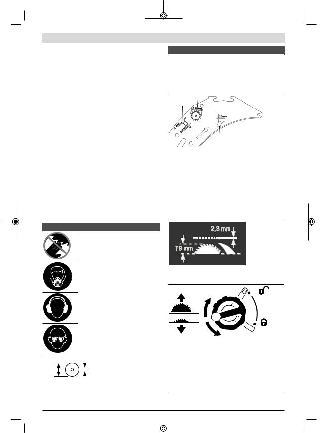
Keep hands away from the cutting area while the power tool is running. Contact with the saw blade can lead to injuries.
Wear a dust mask.
Wear hearing protection. Exposure to noise can cause hearing loss.
Wear safety goggles.
Ø 25.4 MM
Ø 254
MM
Take note of the dimensions of the saw blade. The hole diameter must fit the tool spindle without play. If it is necessary to use reducers, ensure that the dimensions of the re-
Symbols and their meaning
ducer are suitable for the base blade thickness and the saw blade hole diameter, as well as the tool spindle diameter. Wherever possible, use the reducers provided with the saw blade.
The saw blade diameter must match the information specified on the symbol.
A
D
 C B
C B
a The saw blade must be no more than 254 mm in dia-
meter.
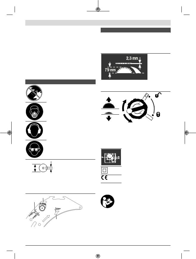
b The riving knife is 2.3 mm thick.
c The cutting direction of the teeth (direction of the arrow on the saw blade) must match the direction of the arrow on the riving knife.
d When changing the saw blade, make sure that the cutting width is no smaller than 2.4 mm and the base blade thickness is no larger than 2.2 mm. Otherwise, there is a risk that the riving knife will hook into the workpiece.
The riving knife is 2.3 mm thick.
The maximum possible workpiece height is 79 mm.
Left-hand side:
Indicates the direction of rotation of the crank for lowering (transport position) and raising (work position) the saw blade.
Right-hand side:
Indicates the position of the locking lever for securing the saw blade and setting the bevel angle (saw blade can be swivelled).
1 609 92A 5P7 | (11.09.2020) |
|
|
|
Bosch Power Tools |
|
|
|
|
|
|
|
|
|
|
|
|
|
|
|
|
|
|
|
Symbols and their meaning
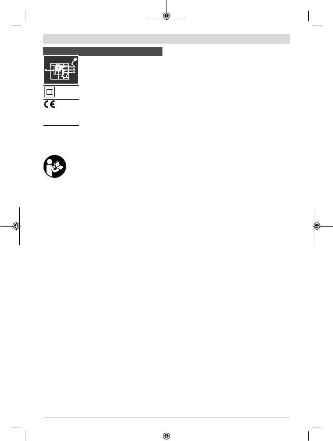
Oil the power tool as necessary at the points indicated.
Protection class II power tools are strengthened or double-insulated.
The CE mark provides confirmation from the manufacturer that the power tool complies with the applicable EU Directives.
Product Description and
Specifications
Read all the safety and general instructions.
Failure to observe the safety and general instructions may result in electric shock, fire and/or serious injury.
Please observe the illustrations at the beginning of this operating manual.
Intended use
The power tool is a stationary machine for cutting in a straight line with and against the grain in hardwood, softwood, chipboard and fibreboard. Mitre angles of –60° to +60° as well as bevel angles of -2° to 47° are possible.
It is also possible to saw aluminium profiles and plastic using the appropriate saw blades.
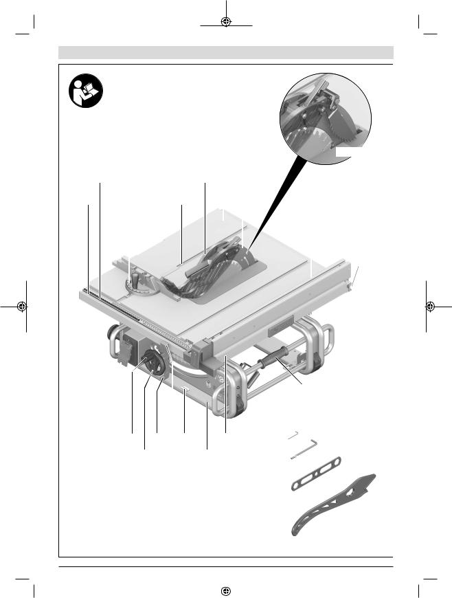
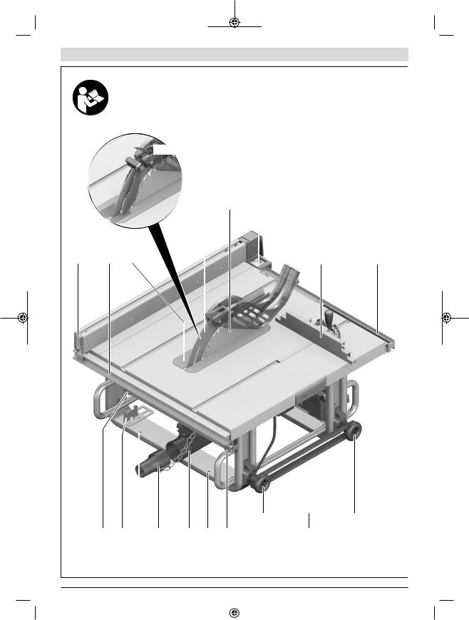
Product Features
The numbering of the product features refers to the diagram of the power tool on the graphics page.
(1)Guide groove for parallel guide
(2)Scale for spacing between saw blade and parallel guide
(3)Angle guide
(4)Recessed handles
(5)Guide groove for angle guide
(6)Protective cover
(7)Saw table
(8)Riving knife
(9)Anti-kickback pawlsA)
(10)Parallel guide
(11)V guide groove on the saw table for the parallel guide
(12)Mounting holes
(13)Carrying handle
(14)Saw table expansion
(15)Fixing clip for the GTA 600 saw stand
(16)Clamping handle for saw table expansion
English | 19
(17)Locking lever for setting the bevel angle
(18)Hand wheel
(19)Crank for raising and lowering the saw blade
(20)On/off switch safety flap
(21)Hex key (2 mm)
(22)Hex key (5 mm)
(23)Ring spanner (23 mm)
(24)Push stick
(25)Adjusting screw for adjusting the clamping force of the parallel guide
(26)Table insert
(27)Saw blade
(28)Magnifying glass
(29)Profile rail
(30)Cable holder
(31)Holding clip for storing the additional parallel guide
(32)Chip ejector
(33)Dust extraction adapter
(34)Bracket for storing the protective cover
(35)Clamping lever for riving knife
(36)Hex socket screws for riving knifeA)
(37)Positioning pins for riving knife
(38)Recesses for table insert
(39)Clamping lever for protective cover
(40)Guide pin for protective cover
(41)Clamping handle for parallel guide
(42)V guide for parallel guide
(43)Additional parallel guide
(44)"Additional parallel guide" fastening set
(45)Guide rail for angle guide
(46)"Profile rail" fastening set
(47)Fastening screw for chip ejector
(48)Push buttons for retracting the guide bolt of the anti-kickback pawlsA)
(49)Clamping nut
(50)Spindle locking lever
(51)Clamping flange
(52)Tool spindle
(53)Mounting flange
(54)Angle indicator (vertical)
(55)Scale for bevel angles
(56)Locking knob for all mitre angles
(57)Angle indicator on the angle guide
(58)Saw table spacing indicator
(59)On button
(60)Knurled nut for profile rail
Bosch Power Tools |
|
|
|
1 609 92A 5P7 | (11.09.2020) |
|
|
|
|
|
|
|
|
|
|
|
|
|
|
|
|
|
|
|
20 | English
(61)Cross-head screw for setting the 0° stop
(62)Stop for 0° bevel angle
(63)Screw for bevel angle indicator
(64)Cross-head screw for setting the 45° stop
(65)Stop for 45° bevel angle
(66)Hex socket screws (5 mm) on the front for adjusting the parallelism of the saw blade
(67)Hex socket screws (5 mm) on the rear for adjusting the parallelism of the saw blade
(68)Screw for saw table spacing indicator
(69)Hex socket screws (5 mm) for adjusting the parallelism of the parallel guide
(70)Screw for parallel guide spacing indicator
(71)Adjusting screws for table insert
(72)Bracket for storing the "additional parallel guide" fastening set
(73)Holding clip for storing the dust extraction adapter
(74)Bracket for storing the anti-kickback pawlsA)
(75)Securing nut for the ring spanner and for hanging the push stick
(76)Bracket for storing the hex key
(77)Holding clip for storing the angle guide
A) Country version 3 601 M30 5C2
Technical Data
Table saw |
|
GTS 10 J |
|
Article number |
|
|
3 601 M30 5.. |
Rated power input |
|
W |
1800 |
Rated voltage |
|
V |
220−240 |
Frequency |
|
Hz |
50/60 |
No-load speed |
|
min-1 |
3650 |
Starting current limitation |
|
|
● |
Weight according to EPTA- |
|
kg |
26.2 |
Procedure 01:2014 |
|
|
|
Protection class |
|
|
/ II |
Dimensions (including detachable parts of the tool) |
|||
Width x depth x height |
|
mm |
640 x 706 x 330 |
Dimensions of suitable saw blades |
|
|
|
Saw blade diameter |
|
mm |
254 |
Base blade thickness |
|
mm |
< 2.2 |
Min. tooth thickness/offset |
|
mm |
> 2.4 |
Hole diameter |
|
mm |
25.4 |
Maximum workpiece dimensions: (see "Maximum workpiece dimensions", page 24)
The specifications apply to a rated voltage [U] of 230 V. These specifications may vary at different voltages and in country-specific models.
Assembly
uAvoid starting the power tool unintentionally. The mains plug must not be connected to the power supply during assembly or when carrying out any kind of work on the power tool.
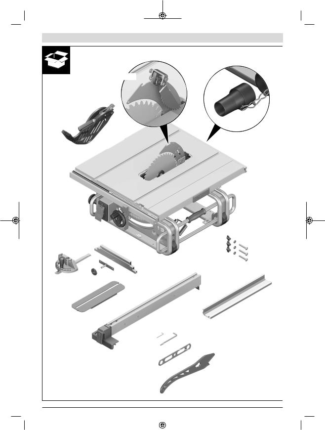
Items included
Check to ensure that all the parts listed below have been supplied before using the power tool for the first time:
–Table saw with fitted saw blade (27) and riving knife (8)
–Angle guide (3)
–Profile rail (29)
–"Profile rail" fastening set (46) (guide plate, knurled nut, screw, washer)
–Parallel guide (10)
–Additional parallel guide (43)
–"Additional parallel guide" fastening set (44) (3 fastening screws, 3 washers, 3 wing nuts)
–Protective cover (6)
–Anti-kickback pawls (9) (Country version
3 601 M30 5C2 )
–Hex key (22)
–Hex key (21)
–Ring spanner (23)
–Push stick (24)
–Table insert (26)
–Dust extraction adapter (33)
Note: Check the power tool for possible damage.
Before continuing to use the power tool, carefully check that all protective devices or slightly damaged parts are working perfectly and according to specifications. Check that the moving parts are working perfectly and without jamming; check whether any parts are damaged. All parts must be fitted correctly and all the conditions necessary to ensure smooth operation must be met.
If the protective devices or any parts become damaged, you must have them properly repaired or replaced by an authorised service centre.
Fitting individual components
–Carefully remove all parts included in the delivery from their packaging.
–Remove all packing material from the power tool and the accessories provided.
–Make sure that you remove the packaging material beneath the motor block.
The following parts of the tool are attached directly to the housing: Push stick (24), ring spanner (23), hex key (22) and (21), parallel guide (10), angle guide (3), dust extraction adapter (33), additional parallel guide (43) with fastening set (44), protective cover (6).
–If you require one of these parts, remove it carefully from its storage location.
1 609 92A 5P7 | (11.09.2020) |
|
|
|
Bosch Power Tools |
|
|
|
|
|
|
|
|
|
|
|
|
|
|
|
|
|
|
|
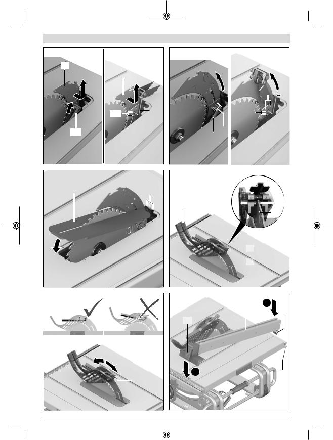
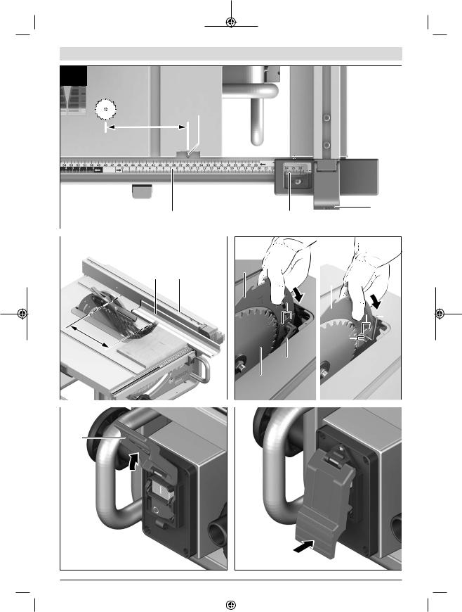
Positioning the riving knife (see figures a1–a2)
Note: If necessary, clean all parts to be fitted before you position them.
–Turn the crank (19) clockwise as far as possible so that the saw blade (27) is in the highest possible position above the saw table.
–Loosen the clamping lever (35). or
country version 3 601 M30 5C2 : Loosen the hex socket screws (36) with the hex key (22).
–Slide the riving knife (8) towards the clamping lever (35) until it can be pulled upwards.
–Pull the riving knife all the way up until it is positioned exactly over the centre of the saw blade.
–Allow both pins (37) to engage in the lower bore holes in the riving knife and then retighten the clamping lever (35) or the hex socket screws (36).
Fitting the table insert (see figure b)
–Hook the table insert (26) into the rear recesses (38) of the tool chamber.
–Guide the table insert down.
–Press down on the table insert until it engages in the front of the tool chamber.
The front side of the table insert (26) must lie flush with or a little below the saw table; the rear must lie flush with or a little above the saw table.
Fitting the protective cover (see figures c1–c2)
Note: Only fit the protective cover when the riving knife is in the top position directly over the centre of the saw blade (see figure a2). Do not fit the protective cover when the riving knife is in the bottom position (position when delivered/ position for sawing grooves) (see figure a1).
–Loosen the clamping lever (39) and remove the protective cover (6) from the bracket (34).
–Hold the saw blade guard (upper metal rail) of the protective cover (6) with one hand, while using the other hand to move the clamping lever (39) up.
–Push the guide pin (40) backwards into the groove on the riving knife (8).
–Move the protective cover (6) down until the saw blade guard (upper metal rail) is parallel with the surface of the saw table (7).
–Push the clamping lever (39) down. The clamping lever must be felt and heard to engage; the protective cover (6) must be securely and safely fitted.
uAlways check that the blade guard can move properly before use. Do not use the power tool if the blade guard cannot move freely and does not close immediately.
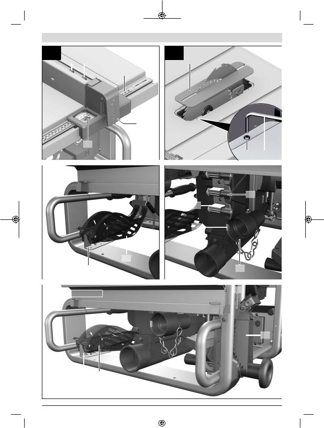
Fitting the parallel guide (see figure d)
The parallel guide (10) can be positioned on either the left or the right of the saw blade.
–Loosen the clamping handle (41) of the parallel guide
(10). This lightens the load on the V guide (42).
English | 21
–First insert the parallel guide with the V guide into the guide groove (11) of the saw table. Then position the parallel guide in the front guide groove (1) of the saw table. The parallel guide can now be moved freely.
–To secure the parallel guide, push the clamping handle
(41) down.
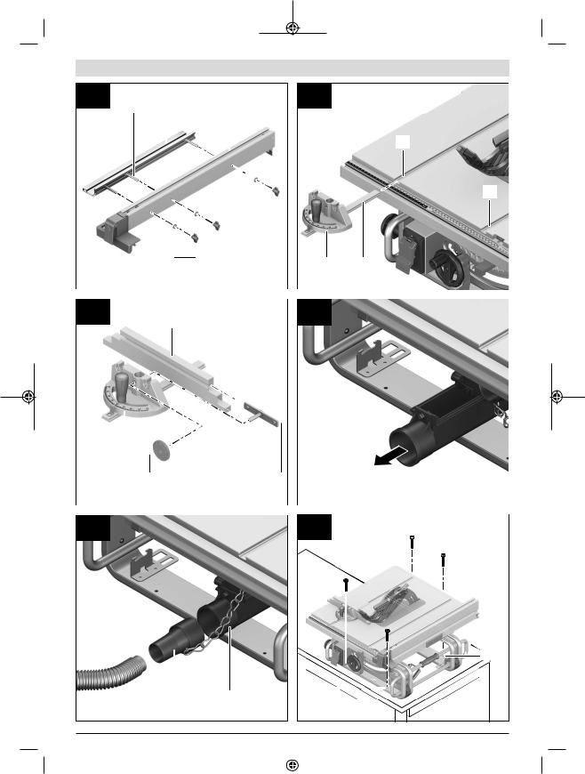
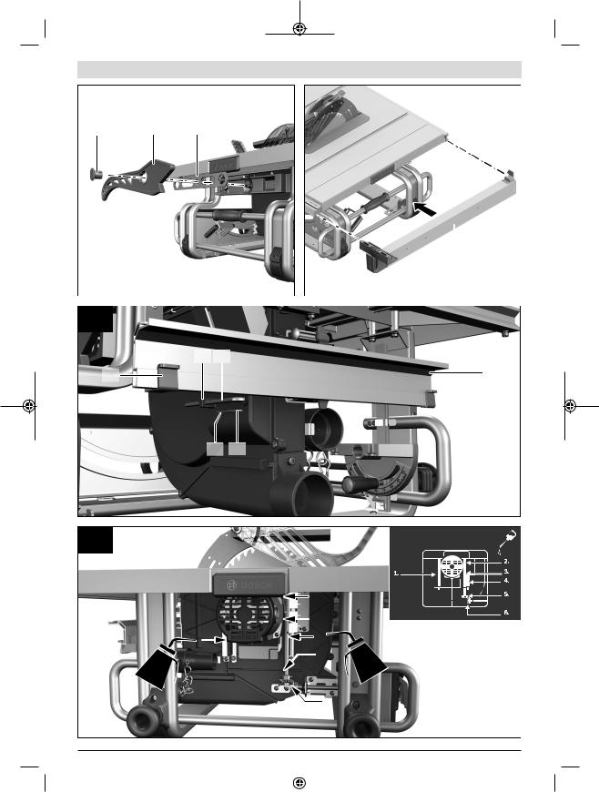
Fitting the additional parallel guide (see figure e)
To saw narrow workpieces and bevel angles, you must fit the additional parallel guide (43) on the parallel guide (10). The additional parallel guide can be fitted on the left or right of the parallel guide (10) as required.
Use the "additional parallel guide" fastening set (44) (two fastening screws, two washers, two wing nuts) for fitting the guide.
–Slide the fastening screws through the lateral holes on the parallel guide (10).
–The heads of the screws are used to guide the additional parallel guide.
–Slide the additional parallel guide (43) over the heads of the fastening screws.
–Place the washers on the fastening screws and tighten the screws using the wing nuts.
Fitting the angle guide (see figure f1-f2)
–Push the rail (45) of the angle guide (3) into one of the guide grooves (5) provided in the saw table.
To make it easier to position long workpieces, the angle guide can be extended with the profile rail (29).
–If necessary, fit the profile rail on the angle guide using the fastening set (46).
Dust/chip extraction
The dust from materials such as lead paint, some types of wood, minerals and metal can be harmful to human health. Touching or breathing in this dust can trigger allergic reactions and/or cause respiratory illnesses in the user or in people in the near vicinity.
Certain dusts, such as oak or beech dust, are classified as carcinogenic, especially in conjunction with wood treatment additives (chromate, wood preservative). Materials containing asbestos may only be machined by specialists.
–Use a dust extraction system that is suitable for the material wherever possible.
–Provide good ventilation at the workplace.
–It is advisable to wear a P2 filter class breathing mask. The regulations on the material being machined that apply in the country of use must be observed.
The dust/chip extraction system can be blocked by dust, chips or fragments of the workpiece.
–Switch the power tool off and pull the mains plug out of the socket.
–Wait until the saw blade has come to a complete stop.
–Determine the cause of the blockage and eliminate it.
uAvoid dust accumulation at the workplace. Dust can easily ignite.
Bosch Power Tools |
|
|
|
1 609 92A 5P7 | (11.09.2020) |
|
|
|
|
|
|
|
|
|
|
|
|
|
|
|
|
|
|
|
22 | English
uTo prevent the risk of fire when sawing aluminium, empty the chip ejector and do not use chip extraction.
Emptying the chip ejector (see figure g)
You can empty the chip ejector (32) to remove workpiece fragments and large chips.
–Switch the power tool off and pull the mains plug out of the socket.
–Wait until the saw blade has come to a complete stop.
–Loosen the fastening screw (47) using the hex key (22).
–Pull out the chip ejector (32) and remove the workpiece fragments and chips.
–Refit the chip ejector on the power tool.
External dust extraction (see figure h)
Use the dust extraction adapter (33) provided to connect a dust extractor to the chip ejector (32).
–Securely attach the dust extraction adapter (33) and the dust extraction hose.
The dust extractor must be suitable for the material being worked.
When extracting dry dust that is especially detrimental to health or carcinogenic, use a special dust extractor.
Stationary or flexible mounting
uTo ensure safe handling, the power tool must be mounted on a flat, stable work surface (e.g. work bench) before use.
Mounting on a work surface (see figure i)
–Use suitable screw fasteners to secure the power tool to the work surface. The holes (12) are used for this purpose.
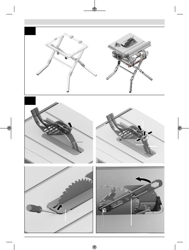
Mounting on a Bosch saw stand (see figure j)
Thanks to their height-adjustable legs, Bosch saw stands (e.g. GTA 600) provide firm support for the power tool on any surface.
uRead all the warnings and instructions included with the saw stand. Failure to observe the warnings and follow instructions may result in electric shock, fire and/or serious injury.
uAssemble the saw stand properly before mounting the power tool. Correct assembly is important to prevent the risk of collapsing.
–Mount the power tool on the saw stand in the transport position.
Changing the saw blade (see figures k1−k4)
uPull the plug out of the socket before carrying out any work on the power tool.
uWhen mounting the saw blade, wear protective gloves. This poses a risk of injury.
uOnly use saw blades the maximum permitted speed of which is higher than the no-load speed of the power tool.
uOnly use saw blades that match the specifications given in this operating manual and that are tested and marked in accordance with EN 847-1
uOnly use saw blades that are recommended by the power tool manufacturer and are suitable for use on the material you want to saw. This prevents the saw tooth tips from overheating and the plastic you want to saw from melting.
uOnly use saw blades that are recommended by the power tool manufacturer and are suitable for using on the material you want to saw.
uDo not use HSS saw blades. Such saw blades can easily break.
Removing the saw blade
–Turn the crank (19) clockwise as far as possible so that the saw blade (27) is in the highest possible position above the saw table.
–Open the clamping lever (39) and pull the protective cover (6) out of the groove on the riving knife (8).
–Additionally, for country version 3 601 M30 5C2 : Press the push buttons (48) and retract the anti-kickback pawls (9) from the hole in the riving knife (8).
–Use a screwdriver to lift the table insert (26) at the front and remove it from the tool chamber.
–Turn the clamping nut (49) using the ring spanner (23) while pulling the spindle locking lever (50) until it engages.
–Keep pulling the spindle locking lever and unscrew the clamping nut anticlockwise.
–Remove the clamping flange (51).
–Remove the saw blade (27).
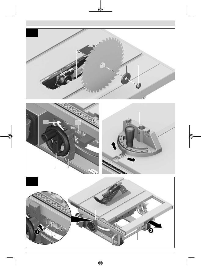
Fitting the saw blade
If necessary, clean all the parts you want to fit before installing them.
–Place the new saw blade on the mounting flange (53) of the tool spindle (52).
Note: Use sufficiently large saw blades. The radial clearance between the saw blade and the riving knife must not exceed 3−8 mm (max.).
uWhen mounting the saw blade, ensure that the cutting direction of the teeth (direction of the arrow on the saw blade) matches the direction of the arrow on the riving knife.
–Fit the clamping flange (51) and the clamping nut (49).
–Turn the clamping nut (49) using the ring spanner (23) while pulling the spindle locking lever (50) until it engages.
–Tighten the clamping nut by turning it clockwise.
–Reinsert the table insert (26).
–Refit the protective cover (6).
–In addition for country version 3 601 M30 5C2 : Refit the anti-kickback pawls (9).
1 609 92A 5P7 | (11.09.2020) |
|
|
|
Bosch Power Tools |
|
|
|
|
|
|
|
|
|
|
|
|
|
|
|
|
|
|
|

Operation
uPull the plug out of the socket before carrying out any work on the power tool.
Transport position and work position of the saw
blade
Transport position
–Remove the protective cover (6), remove the table insert
(26) and place the riving knife (8) in the bottom position. Reinsert the table insert (26).
–Turn the crank (19) anticlockwise until the teeth of the saw blade (27) lie below the saw table (7).
–Push the saw table expansion (14) in fully.
Push the clamping handle (16) down. This fixes the saw table expansion in place.
Work position
–Position the riving knife (8) in the top position directly over the centre of the saw blade, insert the table insert
(26) and fit the protective cover (6).
–Turn the crank (19) clockwise until the top teeth of the saw blade (27) are approx. 3−6 mm above the workpiece.
Setting mitre and bevel angles
To ensure precise cuts, the basic settings of the power tool must be checked and adjusted as necessary after intensive use.
Setting Bevel Angles (saw blade) (see figure A)
The bevel angle can be set between -2° and 47°.
– Loosen the locking lever (17) by turning it anticlockwise.
Note: When the locking lever is fully loosened, gravity causes the saw blade to tilt into a position that corresponds to approximately 30°.
–Pull or push the hand wheel (18) along the slotted link until the angle indicator (54) shows the required bevel angle.
–Hold the hand wheel in this position and retighten the locking lever (17).
For quick and precise setting of the standard bevel angles of 0° and 45°, there are pre-set stops ((62)),((65)).
Setting mitre angles (angle guide) (see figure B)
The mitre angle can be set between 60° (left-hand side) and
60° (right-hand side).
–Loosen the locking knob (56) if it is tightened.
–Turn the angle guide until the angle indicator (57) shows the required mitre angle.
–Retighten the locking knob (56).
Extending the saw table
The free end of long and heavy workpieces must have something placed underneath it or be supported.
English | 23
Saw table expansion (see figure C)
The saw table expansion (14) increases the width of the saw table (7) on the right to a maximum of 625 mm.
–Pull the clamping handle (16) for the saw table expansion all the way up.
–Pull out the saw table expansion (14) to the required length.
–Push the clamping handle (16) down. This fixes the saw table expansion in place.
Adjusting the parallel guide
The parallel guide (10) can be positioned on either the left (black scale) or the right (silver scale) of the saw blade. The marking in the magnifying glass (28) indicates the set distance of the parallel guide to the saw blade on the scale (2). Position the parallel guide on the required side of the saw blade.
Adjusting the parallel guide
when the saw table is not pulled out
–Loosen the clamping handle (41) of the parallel guide
(10). Move the parallel guide until the marking in the magnifying glass (28) indicates the desired distance from the saw blade.
When the saw table is not pulled out, the lower marking on the silver scale applies (2).
–To secure it in place, push the clamping handle (41) back down.
Adjusting the parallel guide
when the saw table is pulled out (see figure D)
–Position the parallel guide on the right of the saw blade. Move the parallel guide until the marking in the magnifying glass (28) shows 26 cm on the lower scale.
To secure it in place, push the clamping handle (41) back down.
–Pull the clamping handle (16) for the saw table expansion all the way up.
–Pull out the saw table expansion (14) until the spacing indicator (58) shows the desired distance from the saw blade on the upper scale.
–Push the clamping handle (16) down. This fixes the saw table expansion in place.
Adjusting the additional parallel guide (see
figure E)
To saw narrow workpieces and bevel angles, you must fit the additional parallel guide (43) on the parallel guide (10). The additional parallel guide can be fitted on the left or right of the parallel guide (10) as required.
When sawing, workpieces can become jammed between the parallel guide and the saw blade, caught in the saw blade as it rises and ejected.
You should therefore set the additional parallel guide so that the end of the guide is between the front tooth of the saw blade and the front edge of the riving knife.
Bosch Power Tools |
|
|
|
1 609 92A 5P7 | (11.09.2020) |
|
|
|
|
|
|
|
|
|
|
|
|
|
|
|
|
|
|
|

24 | English
–To do so, loosen all wing nuts of the fastening set (44) and move the additional parallel guide until only the front two screws are used for attachment.
–Retighten the wing nuts.
Adjusting the riving knife
The riving knife (8) prevents the saw blade (27) from becoming jammed in the kerf. Otherwise there is a risk of kickback occurring if the saw blade catches in the workpiece.
It is therefore important to ensure that the riving knife is set up correctly:
–The radial clearance between the saw blade and the riving knife must not exceed 3−8 mm (max.).
–The thickness of the riving knife must be smaller than the cutting width and larger than the base blade thickness.
–The riving knife must always be aligned with the saw blade.
–For normal cuts, the riving knife must always be in the highest possible position.
Adjusting the riving knife height (see figure F)
The height of the riving knife must be adjusted in order to saw grooves.
uOnly use the power tool for grooving or routing if a suitable protective guard (e.g. tunnel blade guard, featherboard) is in place.
–Open the clamping lever (39) and pull the protective cover (6) out of the groove on the riving knife (8).
To prevent damage to the protective guard, store it in the bracket (34) provided on the housing (see
also figure O1).
–Additionally, for country version 3 601 M30 5C2 :
Press the push buttons (48) together and retract the antikickback pawls (9) from the hole in the riving knife (8). To securely store the anti-kickback pawls, fix them in the bracket (74) provided on the housing (see
also figure O1).
–Turn the crank (19) clockwise as far as possible so that the saw blade (27) is in the highest possible position above the saw table.
–Loosen the clamping lever (35). or
country version 3 601 M30 5C2 : Loosen the hex socket screws (36) with the hex key (22).
–Pull the riving knife off the pins (37) (pull the clamping lever (35) outwards slightly) and push the riving knife (8) down as far as possible.
–Allow both pins (37) to engage in the upper bore holes in the riving knife and then retighten the clamping
lever (35).
Start-up
uPay attention to the mains voltage. The voltage of the power source must match the voltage specified on the rating plate of the power tool.
uProducts that are only sold in AUS and NZ: Use a residual current device (RCD) with a nominal residual current of 30 mA or less.
Switching on (see figure G1)
–Fold up the safety flap (20).
–To start, press the green "on" button (59).
–Drop the safety flap (20) back down.
Switching off (see figure G2)
– Press the safety flap (20).
Power outage
The on/off switch acts as a zero-voltage switch that prevents the power tool from starting up again following a power outage (e.g. if the mains plug is removed during operation).
To restart the power tool following a power outage, press the green "on" button (59) again.
Practical advice
General sawing instructions
uBefore making any cuts, first make sure that the saw blade cannot come into contact with the stops or any other parts of the tool at any time.
uOnly use the power tool for grooving or routing if a suitable protective guard (e.g. tunnel blade guard, featherboard) is in place.
uDo not use the power tool for cutting slots (stopped grooves).
Protect the saw blade against impact and shock. Do not subject the saw blade to lateral pressure.
The riving knife must be aligned with the saw blade in order to prevent the workpiece from jamming.
Do not saw workpieces that have become bent or twisted out of shape. The workpiece must always have a straight edge to face against the parallel guide.
Always store the push stick on the power tool.
Position of the operator (see figure H)
uNever stand directly in line with the saw blade. Always position your body on the same side of the saw blade as the fence. Kickback may propel the workpiece at high velocity towards anyone standing in front and in line with the saw blade.
–Keep hands, fingers and arms away from the rotating saw blade.
Pay attention to the following instructions:
–Hold the workpiece firmly with both hands and press it securely against the saw table.
–When using narrow workpieces or sawing bevel angles, always use the push stick (24) and the additional parallel guide (43) provided.
Maximum workpiece dimensions
Bevel angle |
max. height of the work- |
|
piece [mm] |
0° |
79 |
1 609 92A 5P7 | (11.09.2020) |
|
|
|
Bosch Power Tools |
|
|
|
|
|
|
|
|
|
|
|
|
|
|
|
|
|
|
|

Bevel angle |
max. height of the work- |
|
piece [mm] |
45° |
56 |
Sawing
Making straight cuts
–Adjust the parallel guide (10) to the desired cutting width.
–Place the workpiece on the saw table in front of the protective cover (6).
–Use the crank (19) to raise or lower the saw blade as far up or down as needed to position the top teeth of the saw blade (27) approx. 3−6 mm above the workpiece.
–Switch on the power tool.
–Saw through the workpiece applying uniform feed.
If you apply too much pressure, the tip of the saw blade could overheat and damage the workpiece.
–Switch off the power tool and wait until the saw blade has come to a complete stop.
Sawing a bevel angle
–Set the required saw blade bevel angle.
If the saw blade is tilted to the left, the parallel guide (10) must be to the right of the blade.
–Follow the work steps set out in the (see "Making straight cuts", page 25) section
Sawing mitre angles (see figure I)
–Set the required mitre angle on the angle guide (3).
–Place the workpiece on the profile rail (29).
The profile must not be positioned along the cut line. If it is, loosen the knurled nut (60) and reposition the profile rail.
–Use the crank (19) to raise or lower the saw blade as far up or down as needed to position the top teeth of the saw blade (27) approx. 3−6 mm above the workpiece.
–Switch the power tool on.
–Hold the workpiece against the profile rail (29) with one hand; place your other hand on the locking knob (56) and slide the angle guide slowly forwards in the guide groove
(5).
–Switch off the power tool and wait until the saw blade has come to a complete stop.
Checking and adjusting the basic settings
To ensure precise cuts, the basic settings of the power tool must be checked and adjusted as necessary after intensive use.
Experience and suitable special tools are required for this. A Bosch after-sales service point will handle this work quickly and reliably.
Adjusting the stops for a standard bevel angle 0°/45°
–Bring the power tool into the work position.
–Set the saw blade to a bevel angle of 0°.
–Remove the blade guard (6).
English | 25
Checking (see figure J1)
–Set an angle gauge to 90° and place it on the saw table
(7).
The leg of the angle gauge must be flush with the saw blade
(27) along its entire length.
Setting (see figure J2)
–Loosen the screw (61). This enables the 0° stop (62) to be moved.
–Loosen the locking lever (17).
–Slide the hand wheel (18) towards the 0° stop until the leg of the angle gauge is flush with the saw blade along its entire length.
–Hold the hand wheel in this position and retighten the locking lever (17).
–Retighten the screw (61).
If the angle indicator (54) is not aligned with the 0° mark on the scale (55) following adjustment, loosen the screw (63) using a conventional cross-headed screwdriver and align the angle indicator along the 0° mark.
Repeat the work step above for the bevel angle of 45° (loosen the screw (64); move the 45° stop (65)). The angle indicator (54) must not be repositioned when doing this.
Parallelism of the saw blade with the guide grooves of the angle guide (see figure K)
–Bring the power tool into the work position.
–Remove the blade guard (6).
Checking
–Use a pencil to mark the first left-hand saw tooth that is visible at the back above the table insert.
–Set an angle gauge to 90° and place it on the edge of the guide groove (5).
–Move the leg of the angle gauge until it touches the marked saw tooth and read the distance between the saw blade and the guide groove.
–Turn the saw blade until the marked tooth at the front lies above the table insert.
–Move the angle gauge along the guide groove up to the marked saw tooth.
–Measure the distance between the saw blade and the guide groove again.
The two measured distances must be identical.
Setting
–Loosen the hex socket screws (66) at the front beneath the saw table and the hex socket screws (67) at the rear beneath the saw table using the hex key (22) provided.
–Carefully move the saw blade until it lies parallel with the guide groove (5).
–Retighten all screws (66) and (67).
Adjusting the saw table spacing indicator (see figure L)
–Position the parallel guide on the right of the saw blade. Move the parallel guide until the marking in the magnifying glass (28) shows 26 cm on the lower scale.
To secure it in place, push the clamping handle (41) back down.
Bosch Power Tools |
|
|
|
1 609 92A 5P7 | (11.09.2020) |
|
|
|
|
|
|
|
|
|
|
|
|
|
|
|
|
|
|
|

26 | English
–Pull the clamping handle (16) all the way up and pull the saw table expansion (14) out as far as possible.
Checking
The upper scale (2) of the spacing indicator (58) must show the same value as the marking in the magnifying glass (28) on the lower scale (2).
Setting
–Pull the saw table expansion (14) out fully.
–Loosen the screw (68) with a cross-headed screwdriver and align the spacing indicator (58) along the 26 cm mark on the upper scale (2).
Adjusting the parallelism of the parallel guide (see figure M)
–Bring the power tool into the work position.
–Remove the blade guard (6).
–Loosen the clamping handle (41) of the parallel guide and move it until it touches the saw blade.
Checking
The parallel guide (10) must touch the saw blade along its entire length.
Setting
–Loosen the hex socket screws (69) using the hex key
(22) provided.
–Carefully move the parallel guide (10) until it touches the saw blade along its entire length.
–Hold the parallel guide in this position and push the clamping handle (41) down again.
–Retighten the hex socket screws (69).
Adjusting the clamping force of the parallel guide
The clamping force of the parallel guide (10) can deteriorate after frequent use.
–Tighten the adjusting screw (25) until the parallel guide can be securely fixed to the saw table again.
Adjusting the magnifying glass of the parallel guide (see
figure M)
–Bring the power tool into the work position.
–Remove the protective cover (6).
–Move the parallel guide (10) from the right until it touches the saw blade.
Checking
The marking in the magnifying glass (28) must be in line with the 0 mm mark on the scale (2).
Setting
–Loosen the screw (70) using a cross-headed screwdriver and align the marking along the 0 mm mark.
Adjusting the level of the table insert (see figure N)
Checking
The front side of the table insert (26) must lie flush with or a little below the saw table; the rear must lie flush with or a little above the saw table.
Setting
– Remove the table insert (26).
–Use the hex key (22) to set the correct level of the four adjusting screws (71).
Storage and transport
Storing tool elements (see figures O1–O5)
You can attach certain tool elements to the power tool to store them.
–Detach the additional parallel guide (43) from the parallel guide (10).
–Place all loose components of the tool in their storage compartments on the housing (see the following table).
Fig- |
Tool element |
Storage compartment |
ure |
|
|
O1 |
Protective cover (6) |
Place in the recess on the |
|
|
bracket (34) and secure using |
|
|
the clamping lever (39) |
O1 |
Anti-kickback |
Press the push buttons (48) to- |
|
pawls (9) (Country |
gether and allow them to engage |
|
version |
in the hole of the bracket (74) |
|
3 601 M30 5C2 ) |
|
O2 |
"Additional parallel |
Clip into the brackets (72) |
|
guide" fastening |
|
|
set (44) |
|
O2 |
Dust extraction ad- |
Slide into the holding clips (73) |
|
apter (33) |
|
O3 |
Ring spanner (23) |
Secure in the storage compart- |
|
|
ment using the securing |
|
|
nut (75) |
O3 |
Push stick (24) |
Suspend using the securing |
|
|
nut (75) and slide to secure |
O4 |
Parallel guide (10) |
Turn around, suspend from be- |
|
|
low in the guide rails and secure |
|
|
the clamping handle (41) |
O5 |
Hex key (22) |
Slide into the brackets (76) |
|
Hex key (21) |
|
O5 |
Angle guide (3) |
Slide into the holding clips (77) |
O5 |
Additional parallel |
Slide into the holding clips (31) |
|
guide (43) |
(short side facing up, long side |
|
|
facing the rear) |
Transporting the power tool
Before transporting the power tool, the following steps must be carried out:
–Bring the power tool into the transport position.
–Remove all accessories that cannot be securely fitted to the power tool.
If possible, transport unused saw blades in an enclosed container.
–Slide the saw table expansion (14) in fully and push the clamping handle (16) down to secure it in place.
–Wrap the power cable around the cable holder (30).
–Use the carrying handles (13) to lift or transport the tool.
uOnly use the transport devices to transport the power tool and never the protective devices.
1 609 92A 5P7 | (11.09.2020) |
|
|
|
Bosch Power Tools |
|
|
|
|
|
|
|
|
|
|
|
|
|
|
|
|
|
|
|
Maintenance and Service
Maintenance and Cleaning
uPull the plug out of the socket before carrying out any work on the power tool.
uTo ensure safe and efficient operation, always keep the power tool and the ventilation slots clean.
In order to avoid safety hazards, if the power supply cord needs to be replaced, this must be done by Bosch or by an after-sales service centre that is authorised to repair Bosch power tools.
Cleaning
Always remove dust and chips after working by blowing out with compressed air or using a brush.
Lubricating the power tool
Lubricant:
SAE 10/SAE 20 engine oil
– Oil the power tool as necessary at the points indicated (see figure P).
An authorised Bosch after-sales service point will handle this work quickly and reliably.
uDispose of lubricants and cleaning products in an environmentally friendly manner, taking legal regulations into account.
Noise reduction measures
Measures implemented by the manufacturer:
–Soft start
–Provided with a saw blade specially developed for noise reduction
Measures implemented by the operator:
–Low-vibration mounting on a stable work surface
–Use of saw blades with noise-reducing functions
–Regular cleaning of the saw blade and power tool
Accessories
|
Article number |
Dust bag |
2 610 015 511 |
Dust extraction adapter |
2 610 015 509 |
Y adapter TSVH 3 |
2 610 015 513 |
Angle guide |
2 610 015 507 |
Push stick |
2 610 015 022 |
GTA 600 saw stand |
0 601 B22 001 |
Saw blades for wood and fibreboard, panels and strips
254 x 25.4 mm saw blade, 40 teeth |
2 608 640 901 |
254 x 25.4 mm saw blade, 60 teeth |
2 608 640 902 |
After-Sales Service and Application Service
Our after-sales service responds to your questions concerning maintenance and repair of your product as well as spare parts. You can find explosion drawings and information on spare parts at: www.bosch-pt.com
The Bosch product use advice team will be happy to help you
| 27
with any questions about our products and their accessories.
In all correspondence and spare parts orders, please always include the 10 digit article number given on the nameplate of the product.
Malaysia
Robert Bosch Sdn. Bhd.(220975-V) PT/SMY
No. 8A, Jalan 13/6
46200 Petaling Jaya
Selangor
Tel.: (03) 79663194
Toll-Free: 1800 880188
Fax: (03) 79583838
E-Mail: kiathoe.chong@my.bosch.com
www.bosch-pt.com.my
You can find further service addresses at:
www.bosch-pt.com/serviceaddresses
Disposal
The power tool, accessories and packaging should be recycled in an environmentally friendly manner.
Do not dispose of power tools along with household waste.
 !
!
" "
u 引发事故。
u 燃粉尘或气体。
u 集中会使操作者失去对工具的控制。
击危险。
u 箱。
Bosch Power Tools |
|
|
|
1 609 92A 5P7 | (11.09.2020) |
|
|
|
|
|
|
|
|
|
|
|
|
|
|
|
|
|
|
|
28 |
u |
|
|
|
u |
u |
|
|
|
u |
u |
|
|
|
|
|
u |
u |
RCD RCD |
|
|
|
|
|
u |
u |
|
|
|
|
|
|
|
u |
u/
|
u |
|
|
||
|
||
|
u 衡。
u 或长发可能会卷入运动部件中。
u 减少尘屑引起的危险。
u 害。
u 效、更安全。
u/
u 和防反弹装置有助于降低人身伤害风险。
u 将导致危险。
u 效果将丧失。
u 时锯尾刀防反弹装置无法防止弹回。
u 厚度。
u 
u
|
u |
|
|
1 609 92A 5P7 | (11.09.2020) |
|
|
|
Bosch Power Tools |
|
|
|
|
|
|
|
|
|
|
|
|
|
|
|
|
|
|
|

u 力。如果挡块和刀片之间的距离小于150 mm50 mm“ ”
u 推杆。
u“ ” “ ”
u 工件可能导致意外地接触正在转动的锯片。
| 29
u 锯片不对齐、卡滞或弹回。
u 能带动一件或多件加工件引起弹回。
u 起弹回。
u 锯片会降低卡滞、停转和弹回的风险。
u
回。
机停转。
u 进行清理。
u2 mm
u 在锯片前方、与锯片呈直线排列的人。
u 控危险。
u 滑不平的地面会引发意外事故。
u 动或倾翻。
u/
u 确保电锯安全运行和最优性能而专门设计。
u 身伤害。
u 勿对台锯使用砂轮、钢丝刷或磨轮。
卡滞或弹回。
u 板在发生弹回时有助于控制加工件。
u 锯片割伤。
u 属粉尘可能会起火燃烧或爆炸。
Bosch Power Tools |
|
|
|
1 609 92A 5P7 | (11.09.2020) |
|
|
|
|
|
|
|
|
|
|
|
|
|
|
|
|
|
|
|
30 |
uEN 847-1
u 及适合加工物料的锯片。
工具。
有受伤危险。
力。
Ø 25.4 MM
Ø 254
MM
根据锯片厚度、锯片孔径以及工具主轴直径来调整 缩径套的尺寸。尽可能使用与锯片配套的缩径套。 锯片直径必须与图标上的说明一致。
A
D
 C B
C B
a254
b2.3
c 开楔上的箭头方向一致。
d2.42.2
2.3
79


II
CE
下警告和说明可能导致电击、着火和/
切角度的范围为−60° +60°-2° 47°
1 609 92A 5P7 | (11.09.2020) |
|
|
|
Bosch Power Tools |
|
|
|
|
|
|
|
|
|
|
|
|
|
|
|
|
|
|
|
Loading...