

Bosch GHO12V-08 Owner's Manual
1-877-BOSCH99 (1-877-267-2499) www.boschtools.com
Operating/Safety Instructions
Consignes d’utilisation/de sécurité
Instrucciones de funcionamiento y seguridad
IMPORTANT
Read Before Using
●
IMPORTANT
Lire avant usage
●
IMPORTANTE
Leer antes de usar
For English Version
See page 2
●
Version française
Voir page 16
●
Versión en español
Ver la página 31
Call Toll Free for Consumer Information and Service Locations
Pour obtenir des informations et les adresses de nos centres de service après-vente, appelez ce numéro gratuit
Llame gratis para obtener información para el consumidor y ubicaciones de servicio
GHO12V-08
2610052962_GHO12V-08 7/2/19 1:43 PM Page 1
-2-
Work area safety
Ke ep work area clean and well lit.
Cluttered or dark areas invite accidents.
Do not operate power tools in explosive
atmospheres, such as in the presence of
flammable liquids, gases or dust. Power
tools create sparks which may ignite the
dust or fumes.
Keep children and bystanders away while
operating a power tool. Distractions can
cause you to lose control.
Electrical safety
Power tool plugs must match the outlet.
Never modify the plug in any way. Do not
use any adapter plugs with earthed
(grounded) power tools. Unmodified
plugs and matching outlets will reduce
risk of electric shock.
Avoid body contact with earthed or
grounded su rfaces, such as pipes,
radiators, ranges and refrigerators. There
is an increased risk of electric shock if
your body is earthed or grounded.
Do not expose power tools to rain or wet
conditions. Water entering a power tool
will increase the risk of electric shock.
Do not abuse the cord. Never use the
cord for carrying, pulling or unplugging the
power tool. Keep cord away from heat,
oil, sharp edges or moving parts. Damaged
or entangled cords increase the risk of
electric shock.
When operating a power tool outdoors,
us e an exten sion cord suitable for
outdoor use. Use of a cord suitable for
outdoor use reduces the risk of electric
shock.
If operating a power tool in a damp
location is unavoidable, use a Ground
Fa ult Circuit In terrupte r ( GFCI)
protected supply. Use of an GFCI reduces
the risk of electric shock.
Personal safety
Stay alert, watch what you are doing and
use common sense when operating a
power tool. Do not use a power tool
while you are tired or under the influence
Read all safety warnings, instructions, illustrations and specifications
provided with this power tool. Failure to follow all instructions listed
below may result in electric shock, fire and/or serious injury.
SAVE ALL WARNINGS AND INSTRUCTIONS FOR FUTURE REFERENCE
The term “power tool” in the warnings refers to your mains-operated (corded) power
tool or battery-operated (cordless) power tool.
General Power Tool Safety Warnings
Safety Symbols
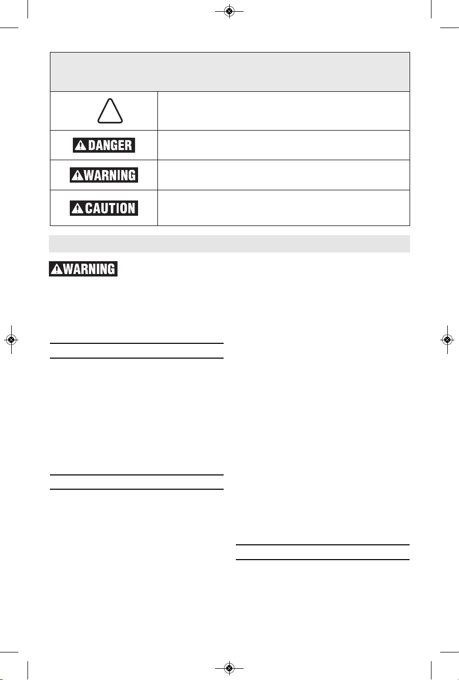
The definitions below describe the level of severity for each signal word. Please read the
manual and pay attention to these symbols.
!
This is the safety alert symbol. It is used to alert you to
potential personal injury hazards. Obey all safety messages
that follow this symbol to avoid possible injury or death.
DANGER indicat es a ha zardous situ ation wh ich, if not
avoided, will result in death or serious injury.
WARNING indicates a hazardous situation which, if not
avoided, could result in death or serious injury.
CAUTION indicate s a hazardous situation which, if n ot
avoided, could result in minor or moderate injury.
2610052962_GHO12V-08 7/2/19 1:43 PM Page 2

-3-
General Power Tool Safety Warnings
of drugs, alcohol or medication. A moment
of inattention while operating power tools
may result in serious personal injury.
Use personal protective equipment.
Always wear eye protection. Protective
equipment such as dust mask, non-skid
safety shoes, hard hat, or hearing
protection used for appropriate conditions
will reduce personal injuries.
Prevent unintentional starting. Ensure the
switch is in the off-position before
connecting to power source and / or
battery pack, picking up or carrying the
tool. Carrying power tools with your finger
on the switch or energizing power tools
that have the switch on invites accidents.
Remove any adjusting key or wrench
before turning the power tool on. A
wrench or a key left attached to a rotating
pa rt o f the power tool may result in
personal injury.
Do not overreach. Keep proper footing
and balance at all times. This enables
be t ter control of the po wer tool in
unexpected situations.
Dr ess proper ly. Do not we ar loose
clothing or jewelry. Keep your hair,
clothing and gloves away from moving
parts. Loose clothes, jewelry or long hair
can be caught in moving parts.
If devic es ar e prov ided for the
co nnection of dust extractio n and
collection facilities, ensure these are
connected and properly used. Use of dust
co l lection can red uce dust-re lated
hazards.
Do not let familiar ity gain ed from
fr equent use of tools allow yo u to
become complacent and ignore tool
safety principles. A careless action can
cause severe injury within a fraction of a
second.
Power tool use and care
Do not force the power tool. Use the
correct power tool for your application.
The correct power tool will do the job
better and safer at the rate for which it
was designed.
Do not use the power tool if the switch
does not turn it on and off. Any power
tool that cannot be controlled with the
switch is dangerous and must be repaired.
Disconnect the plug from the power
source and/or remove the battery pack, if
detachable, from the power tool before
making any adjustments, chang ing
accessories, or storing power tools. Such
preventive safety measures reduce the risk
of starting the power tool accidentally.
Store idle power tools out of the reach of
children and do not allow persons
unfamiliar with the power tool or these
instructions to operate the power tool.
Power tools are dangerous in the hands of
untrained users.
Maintain power tools and accessories.
Check for misalignment or binding of
moving parts, breakage of parts and any
other condition that may affect the power
tool’s operation. If damaged, have the
power tool repaired before use. Many
accidents are caused by poorly maintained
power tools.
Keep cutting tools sharp and clean.
Properly maintained cutting tools with
sharp cutting edges are less likely to bind
and are easier to control.
Use the power tool, accessories and
tool bits etc. in accordance with these
instructions, taking into account the
working conditions and the work to be
performed. Use of the power tool for
operations different from those intended
could result in a hazardous situation.
Keep handles and grasping surfaces dry,
cl ean and f ree from oil and grease.
Slippery handles and grasping surfaces do
not allow for safe handling and control of
the tool in unexpected situations.
Battery tool use and care
Recharge only wi t h the charger
specified by the manufacturer. A charger
that is suitable for one type of battery
pack may create a risk of fire when used
with another battery pack.
Use power tools only with specifically
designated battery packs. Use of any
other battery packs may create a risk of
injury and fire.
When battery pack is not in use, keep it
aw ay fro m othe r meta l obje cts li ke
paper clips, coins, keys, nails, screws,
or other small metal objects that can
make a connection from one terminal to
2610052962_GHO12V-08 7/2/19 1:43 PM Page 3

-4-
Safety Rules for Cordless Planers
Wait for the cutter to stop before setting
the tool down. An exposed rotating cutter
may engage the surface leading to possible
loss of control and serious injury.
Use clamps or another practical way to
secure and support the workpiece to a
stable platform. Holding the workpiece by
your hand or against the body leaves it
unstable and may lead to loss of control.
Secure the material being planed. Never
hold it in your hand or across legs. Small
workpiece must be adequately secured so
that the rotating planer blades will not pick
it up during forward motion of the planer.
Unstable support can cause the blades to
bind causing loss of control and injury.
Always start the planer before blade is in
contact with the workpiece and allow the
bl ade to come to full s peed. Tool can
vibrate or chatter if blade speed is too slow
at beginning of cut and possibly kickback.
Check the blade guard for proper closing
before each use. Do not operate tool if the
blade guard does not move freely and
close instantly. Never clamp or tie the
blade guard in the open position. Hands
contacting the blade can cause serious
personal injury.
Keep hands away from the blade. Hands
contacting the blade can cause serious
personal injury.
Check the workpiece for nails, if there are
na ils, eithe r re move or s et t hem w ell
below intended finished surface. If the
planer blades strike objects like nails it may
cause the tool to kickback and serious
personal injury may result.
Disconnect battery pack from tool before
ma king any as sembl y, adjustment s or
changing accessories. Such preventive
safety measures reduce the risk of starting
the tool accidentally.
After changing blades, rotate the blade
cylinder (cutter drum) to make sure blades
are not hitting any part of the blade head
housing and the blade locking screws are
tight. Spinning blades could strike tool
hous i n g a n d d a m a g e t o o l a s w e l l a s
possible injury.
Always hold the tool firmly with both
hands. This provides maximum control for
the operator.
Never pull the planer backward over the
workpiece. Loss of control may occur.
Do not put fingers or any objects into the
shavings exhaust channel or clean out
shavings while tool is running. Contact
with blade drum will cause injury.
General Power Tool Safety Warnings
another. Shorting the battery terminals
t
ogether may cause burns or a fire.
Under abusive conditions, liquid may be
ejected from the battery, avoid contact.
If contact accidentally occurs, flush with
water. If l i q u i d contacts eyes,
additionally seek medical help. Liquid
eject e d from the battery may cause
irritation or burns.
Do not use a battery pack or tool that is
damaged or modified. Damaged or modified
batt e r i e s may e x h ibit unpre d i c t a b l e
behaviour resulting in fire, explosion or risk
of injury.
Do not expose a battery pack or tool to
fire or excessive temperature. Exposure
to fire or temperature above 265 °F may
cause explosion.
Follow all charging instructions and do
not charge the battery pack or tool
outside the temperature range specified
i
n the instructions. Charging improperly
or at temperatures outside the specified
range may damage th e battery and
increase the risk of fire.
Service
Have your power tool serviced by a
qualified re pair p erson using only
identical replacement parts. This will
ensure that the safety of the power tool is
maintained.
Never service damaged battery packs.
Service of battery packs should only be
pe r formed by the manufac turer or
authorized service providers.
2610052962_GHO12V-08 7/2/19 1:43 PM Page 4

-5-
Additional Safety Warnings
Develop a periodic maintenance schedule
for your tool. When cleaning a tool be
careful not to disassemble any portion of
the tool since inte r n a l wires may b e
mi splaced or pinche d or safety guar d
retu r n springs m a y be improperly
mounted. Certain cleaning agents such as
gasoline, carbon tetrachloride, ammonia,
etc. may damage plastic parts.
Ensure the switch is in the off position
before inserting battery pack. Inserting the
battery pack into power tools that have the
switch on invites accidents.
Some dust created by
power sanding, sawing,
grinding, drilling, and other construction
activities contains chemicals known to
caus e cancer, birth def e c t s or other
reproductive harm. Some examples of
these chemicals are:
• Lead from lead-based paints,
• Crystalline silica from bricks and cement
and other masonry products, and
• Arsenic and chromium from chemically-
treated lumber.
Your risk from t hese exp osures v arie s,
depending on how often you do this type of
work. To reduce your exposure to these
chemicals: work in a well ventilated area,
and work with approved safety equipment,
such as those dust masks that are specially
designed to filter out microscopic particles.
Disconnect battery pack from tool if it
becomes necessary to remove shavings.
The blades are hidden from view and you
may be cut if blade is contacted.
Never use dull or damaged blades. Sharp
blad e s must be handled with ca r e .
Damaged blades can snap during use. Dull
blades require more force to push the tool,
possibly causing the blade to break.
Safety Rules for Cordless Planers
2610052962_GHO12V-08 7/2/19 1:43 PM Page 5
-6-
Symbols
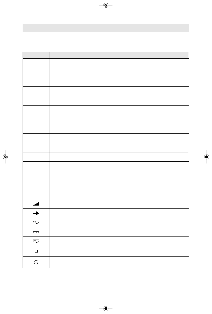
Important: Some of the following symbols may be used on your tool. Please study them
and learn their meaning. Proper interpretation of these symbols will allow you to operate
the tool better and safer.
Symbol Designation / Explanation
V Volts (voltage)
Ah Amp hour (measurement of battery capacity)
A Amperes (current)
Hz Hertz (frequency, cycles per second)
W Watt (power)
kg Kilograms (weight)
min Minutes (time)
s Seconds (time)
⌀
Diameter (size of drill bits, grinding wheels, etc.)
n
0
No load speed (rotational speed at no load)
n Rated speed (maximum attainable speed)
.../min
Revolutions or reciprocation per minute (revolutions, strokes, surface
speed, orbits etc. per minute)
0 Off position (zero speed, zero torque...)
1, 2, 3, ...
I, II, III,
Selector settings (speed, torque or position settings. Higher number
means greater speed)
0
Infinitely variable selector with off (speed is increasing from 0 setting)
Arrow (action in the direction of arrow)
Alternating current (type or a characteristic of current)
Direct current (type or a characteristic of current)
Alternating or direct current (type or a characteristic of current)
Class II construction (designates double insulated construction tools)
Earthing terminal (grounding terminal)
2610052962_GHO12V-08 7/2/19 1:43 PM Page 6
-7-
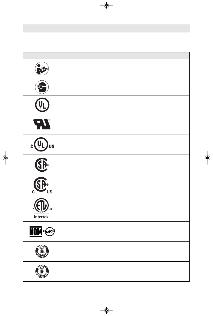
Important: Some of the following symbols may be used on your tool. Please study them
and learn their meaning. Proper interpretation of these symbols will allow you to operate
the tool better and safer.
Symbols
Symbol Designation / Explanation
Alerts user to read manual
Alerts user to wear eye protection
This symbol designates that this tool is listed by Underwriters
Laboratories.
This symbol designates that this component is recognized by
Underwriters Laboratories.
This symbol designates that this tool is listed by Underwriters
Laboratories, to United States and Canadian Standards.
This symbol designates that this tool is listed by the Canadian
Standards Association.
This symbol designates that this tool is listed by the Canadian
Standards Association, to United States and Canadian Standards.
This symbol designates that this tool is listed by the Intertek Testing
Services, to United States and Canadian Standards.
This symbol designates that this tool complies to NOM Mexican
Standards.
Designates Li-ion battery recycling program
Designates Ni-Cad battery recycling program
2610052962_GHO12V-08 7/2/19 1:43 PM Page 7
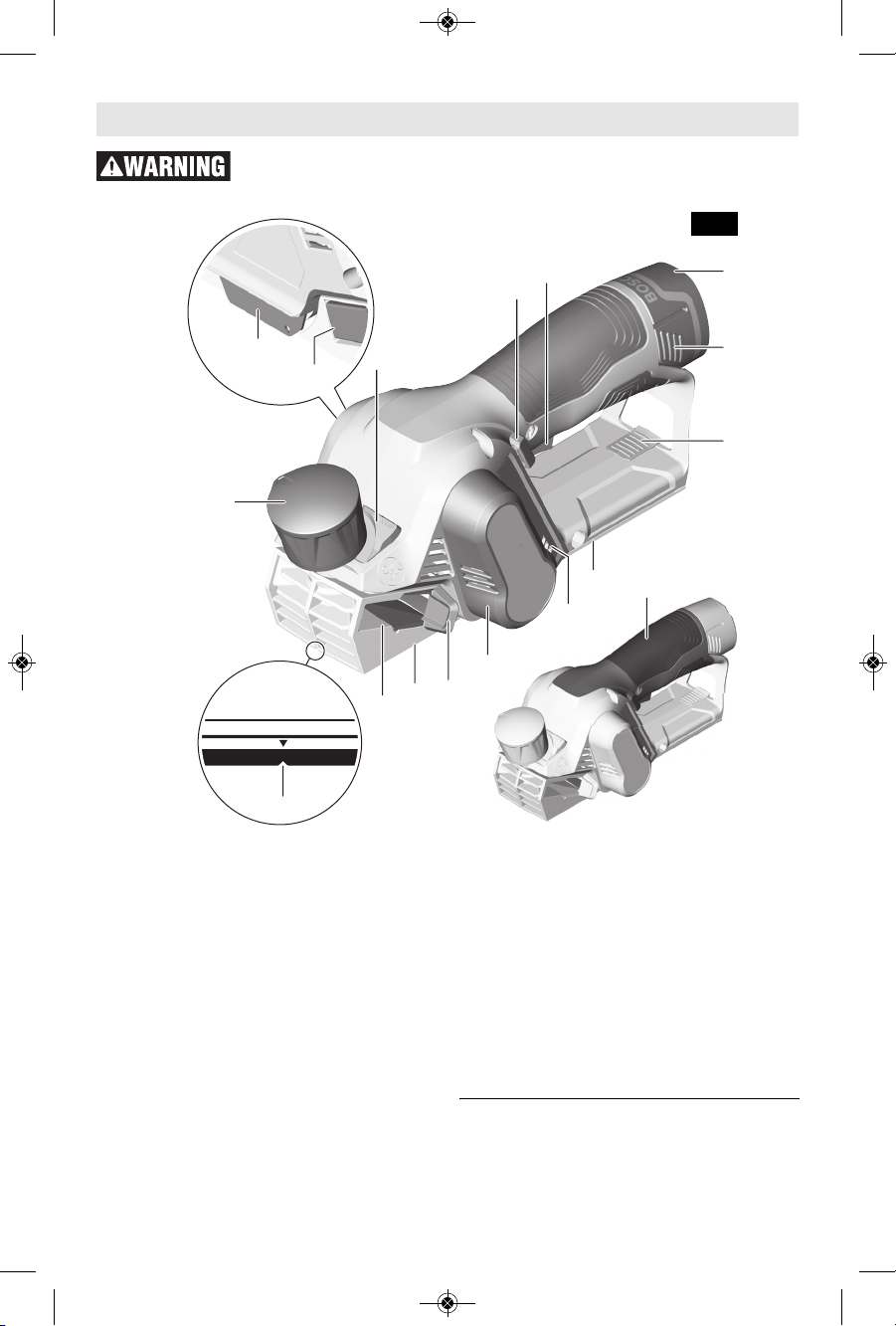
Functional Description
Disconnect battery pack from tool before making any assembly,
adjustments or changing accessories. Such preventive safety measures
reduce the risk of starting the tool accidentally.
-8-
8
12
2
9
13
27
12
11
10
3
4
1
6
5
7
14
15
1 Depth adjustment knob
2 Max. planing depth button
3 Lock-off button
4 Trigger switch
5 Battery pack*
6 Battery release tabs
7 Spare blade drawer
8 Blade guard
9 Rear shoe
10 Battery charge condition indicator
11 Belt cover
12 Shavings diverter
13 Adjustable front shoe
14 Chamfer V-groove
15 Handle
16 Blade / cutter†
17 Blade wrench†
18 Blade drum†
19 Blade clamp†
20 Clamping screw (2x)†
21 Dust extraction hose (35 mm)* †
22 Shavings/dust bag* †
23 Vacuum adapter* †
24 Latch†
25 Bosch hose snap-fastener†
26 Planer stand†
27 Shavings exhaust channel
* Sold separately
† Not shown in this picture
Fig. 1
2610052962_GHO12V-08 7/2/19 1:43 PM Page 8
-9-
Battery Packs/Chargers
Please refer to the battery/charger list, included with your tool.
Specifications
Cordless Planer GHO12V-08
Voltage 10.8V /12V max
No load speed (n0) 14,500/min
Maximum
Capacities
Planing depth 0 - 0.04" (0 - 1.0mm)
Max. planing depth 0.04" - 0.08" (1.0 - 2.0mm)
Rabbeting depth 0 - 0.67" (0 - 17mm)
Cutting width 2.2" (56mm)
Allowed
ambient
temperature
– during charging
– during operation
– during storage
32...113 °F (0...+45 °C)
–4...122 °F (–20...+50 °C)
32…122 °F (0…+50 °C)
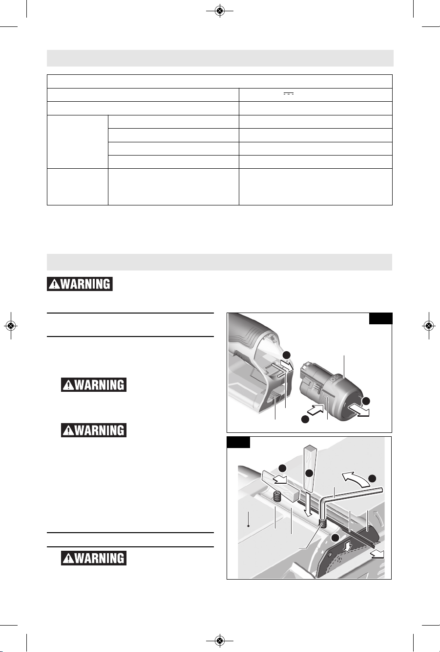
Assembly
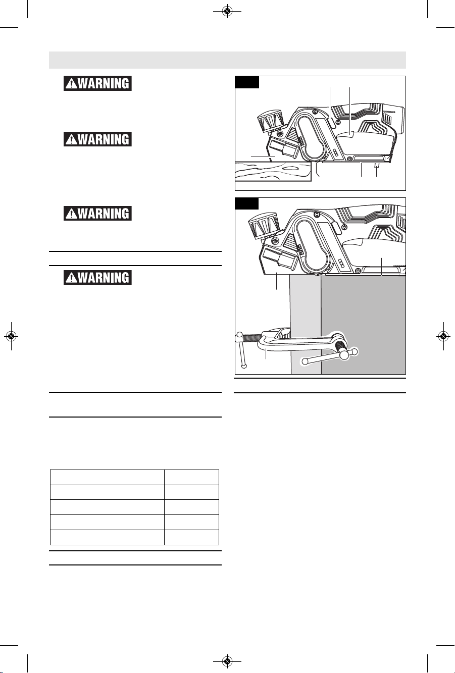
Inserting and Releasing
Battery Pack
Rele a s e battery pack from tool by
pressing on both sides of the battery
release tabs 6 and pull the battery 5 out
(Fig. 2).
If battery rel e a s e
tabs are cracked or
otherwise damaged, do not insert into
tool . B a t t e r y can fa l l out du r i ng
operation.
Ensure the switch is
in the off po s i t ion
before inserting battery pack. Inserting
the battery pack into power tools that
have the switch on invites accidents.
To insert battery, align battery and slide
battery pack into tool until it locks into
position. Do not force.
For best performance we recommend
using batteries with a capacity of at
least 2.5 Ah.
Planer blades
The planer blades are
sharp and fragile and
must be handled carefully to avoid
injury to the user or damage to the
blades.
Disconnect battery pack from tool before making any assembly,
adjustments or changing accessories. Such preventive safety measures
reduce the risk of starting the tool accidentally.
17
6
5
7
B
A
C
Fig. 2
20
19
18
17
13
16
8
A
B
D
C
Fig. 3
2610052962_GHO12V-08 7/2/19 1:43 PM Page 9
Use only Bosch
PA12 0 8 plan e r
blades. Using other planer blades may
cause injuries.
Wear prot e c t i v e
glov e s when
ch a nging planer blad e s. Ed ges a re
sharp and may cause injury.
The PA1208 planer blades have two
cutting edges, a nd may be reversed
when one of the cutting edges becomes
dull or chipped.
Do not attempt to sharpen or use
resharpened used blades of any kind.
Use only blades designated for use with
this model, because other blades will
cause vibration, decrease perfomance
and may not clamp securely in blade
holder.
BLADE AND WRENCH STORAGE
AREA
When the b a t t e r y pack 5 h a s been
removed from the tool, there is a blade
wrench 17 that is conveniently located
inside the handle, where it is always
hand y a n d u n l i kely to get lost or
misplaced (Fig. 2).
A spare blade can be stored in the blade
drawer 7 (Fig. 2)
REVERSING OR REPLACING
BLADES
To reverse or replace the blade 16:
A. Loosen the clamping screws 20 with
blade wrench 17.
B. If necessary, loosen the blade clamp
19 by giving it a light blow with a
wooden wedge.
C. With the blade clamp 19 loosened,
push the blade guard 8 down.
D. Use a piece of wood to slide the
blade 16 lengthwise out of the
blade/cutter drum 18, taking care to
keep your fingers away from the
sharp edges of the blade (Fig. 3).
If the blade is gummed and difficult to
remove, you may clean the blade with
mineral spirits, lacquer thinner or alcohol.
Clean all surfaces before reinstalling the
new blade, as this wi l l ensure an
accurate blade setting and proper tool
performance.
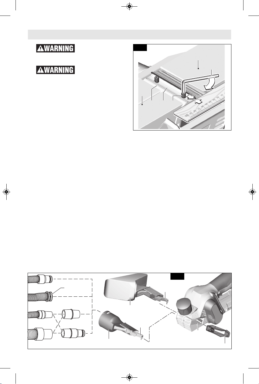
BLADE ALIGNMENT
The blade should be centered relative to
the front 13 and rear 9 shoes (Fig. 4).
Rotate the blade drum 18 by hand to
verify that the blade doesn’t touch to
any other part of the tool.
Make sure the blade sits correctly in the
holder groove of the cutter drum.
Ensure that the blade aligned flush with
the side edge of the rear shoe 9 (Fig. 4).
You may then secure the blade clamp 19
by tightening the screws 20. Your planer
is ready for use.
Assembly
18 19 20
17
9
13
Fig. 4
24
24
1¼ hose
35mm hose
Bosch VH-series hose
VAC024
VAC002
1½ hose
27
13
23
22
25
Fig. 5
-10-
2610052962_GHO12V-08 7/2/19 1:43 PM Page 10
-11-
Assembly
Shavings Extraction
Do not reach into the
shavings ejector with
your hands. They could be injured by
rotating parts.
To e n s u r e op t i mum ex traction of
shavings and dust, always work with
external dust extraction or the shavings
bag (both sold separately).
GHO1 2 V - 0 8 of f ers several ways of
dealing with wood shavings and dust
(Fig. 5):
SHAVINGS DIVERTER
Shavings diverter 13 lets you direct the
flow of shavings and dust to one of the
sides of the planer. To use it, simply
insert the diverter 13 into the exhaust
channel 27 on the side you prefer the
shavings to come out.
If y o u remove the diver t e r 13, the
shavings will be ejected on both sides of
the planer.
Clean the shavings diverter 13 regularly.
For that, switch off the power tool.
Remove the shavings ejector and shake
it out. Use a suitable tool (e.g. a piece of
wood, etc.) to clean a clogged shavings
diverter.
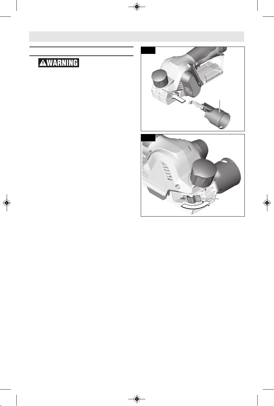
SHAVINGS/DUST BAG
(Sold separately)
Shavings/dust bag 22 is suitable for
small volume tasks. It can be attached
to either side of the planer.
- Remove the diverter 13 or any other
attach ment out of the exhaust
channel 27 (Fig. 5).
- Insert the shav ings bag into the
exhaust channel 27 (Fig. 5).
- Lock the latch 24 as shown in Fig. 7.
VACUUM ADAPTER
(Sold separately)
Vacuum adapter 23 lets you connect the
planer to a vacuum cleaner. The vacuum
adapter can be attached to either side
of the planer.
- Remove the diverter 13 or any other
attach ment out of the exhaust
channel 27 (Fig. 6).
- Insert the vacuum adapter into the
exhaust channel 27.
- Lock the latch 24 as shown in Fig. 7.
- Insert the vacuum hose 21 into the
vacuum adapter 23 (Fig. 5).
NOTE: Bosch VH-series hoses can be
connected using the snap fasteners 25
on those hoses. Other Bosch hoses and
some other tool manufacturers’ vacuum
hoses will also connect directly to the
adapter 23. For connection to 1¼" and
1½" hoses, use the Bosch VAC024 or
VAC002 adapter (sold separately).
- Connect the vacuum hose 21 to a
vacuum clean er (both sold
separately).
The vacuum cleaner must be suitable
for the material being worked.
When vac u u m i n g dr y du st that is
especially detrimenta l t o h ealth or
carcinogenic, use a special vacuum
cleaner / dust extractor.
24
Fig. 7
23
Fig. 6
2610052962_GHO12V-08 7/2/19 1:43 PM Page 11
-12-
Disconnect battery
pack from tool
befo r e maki n g any assembl y ,
adjustments or changing accessories.
Such preventive safety measures reduce
the risk of starting the tool accidentally.
Chec k the blade
guar d f or proper
clos i n g before e a c h use. Do not
operate tool if the blade guard does
not move freely and close instantly.
Never clamp or tie the blade guard in
the open position. Hands contacting the
blade can cause serious personal injury.
Keep hands away
from the blade.
Hands contacting the blade can cause
serious personal injury.
Trigger "ON/OFF" Switch
Hold the t o o l with
both hands while
starting the tool, since torque from the
motor can cause the tool to twist.
TO TURN THE TOOL “ON”: Depress the
“Lock-OFF” button 3 on either side of the
tool and squeeze the trigger switch 4.
TO TU RN THE TOOL “OF F”: Sim ply
release the trigger switch 4.
To increase switch life , d o not turn
switch on and off while tool and drum
are held against a workpiece.
Battery Charge Condition
Indicator
Your tool is equipp e d with charge
condition indicator lights 10 (Fig. 1).
The indicator lights show the charge
cond i t i o n of the battery for a few
seconds after tool activation.
Convenience Brake
When the trigger is released it activates
the electrical brake to stop the blade
quickly. This feature is especially useful
when making repetitive cuts.
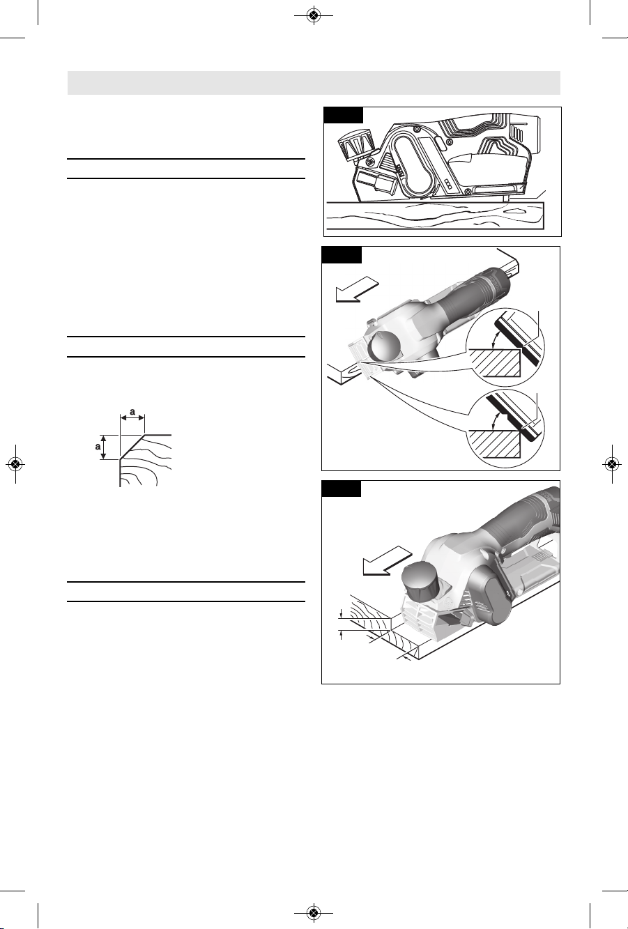
Planing Action
Proper planing action helps to achieve
the desired result. With practice and
expe r i e n c e , it wi l l become s e c o n d
nature. Make sure that the workpiece is
held in place securely on your work
surface, and standing comfortably, hold
the planer firmly with both hands.
A. With the planer fully adjusted, place
the front shoe 13 on the workpiece,
(be certain that the blade 16 is not in
contact with the work) and start the
planer as described earlier.
B. With pressure on the front shoe 13
feed the planer steadily until the full
length of the rear shoe 9 passes over
the edge of the workpiece. (Fig. 8)
C. Then gradually transfer pressure to
the rear shoe 9, and continue planing
to the end of the cut.
D. If pressure is not maintained over the
rear shoe 9 through the end of the
cut, a divot may be created in the
workpiece once the front shoe 13
LED Capacity
3 continuous green lights > 2/3
2 continuous green lights > 1/3
1 continuous green light < 1/3
1 flashing green light reserve
Operating Instructions
916
3 4
13
26
Fig. 8
32
13
9
3031
Fig. 9
2610052962_GHO12V-08 7/2/19 1:43 PM Page 12
-13-
clear the end of the workpiece 30. To
minimize this possibility, use a 3-way
edge clamp 32 (not included) to hold
a piece of scrap wood 31 (at least
1-1/2" [38 mm] thick) on the end of
the workpiece 30, aligned with the
surface to be planed (Fig. 9). Doing
this moves the location of a potential
divot off the workpiece and on to the
piece of scrap wood.
E. Feed the planer at a uniform and
reasonable rate that does not put
excessive strain on the motor or
blade, (do not pull the planer back
over the surface already cut.)
F. Use progressive cuts until you are
near the desired depth, and then readjust to a thin cut for the final pass
to obtain a good surface finish.
The motor may stall
if improperly used or
overloaded. Reduce the pressure (feed
rate) or depth of cut to prevent possible
damage to the tool if the motor labors.
Depth of Cut and Feed Rate
The cutting depth (planing depth) is
determined by the difference in height
between the adjustable front shoe 13
and the fixed rear shoe 9 of the planer.
The depth knob 1 adjusts the front shoe
13, w hich retrac ts and exposes the
blade and determines the amount of
material removed from the workpiece.
The appropriate depth of cut and feed
rate depends on the workpiece material:
To avoid clogging and/or damage to the
motor, a thinner cut and/or a slower
feed rate may be needed if the material
has any of th e s e charac t e r i s t ics:
hard n e s s ; gummin e s s , sappin e s s ,
moisture, paint, varnish and/or knots.
Also, when planing against the grain or
across the grain rather than with the
grain, a shallower cut and/or slower
feed r ate is r e q u i r ed. Whenever
possible, test by planing a similar piece
of scrap material.
Use multiple, progressive cuts to
achieve the total desired depth.
Start with a thin cut. If the planer moves
freely through the workpiece with no
excessive load on the motor, the depth
setting can be increased before the next
cut.
When near the desired total depth, re-
adju s t the planing depth to a th i n
setting for the final cut to obtain a good
surface finish.
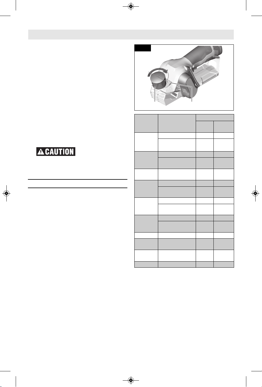
ADJUSTING THE DEPTH OF CUT
- Turn depth adjustment knob 1 as
shown in Fig. 10 to increase the
depth of cut from 0 to .04 inches.
- To use the extended depth of cut
range, press and hold the Max button
2 and keep turning the depth knob 1
to set the depth of cut between .04
and .08 inches.
- Refer to the table to determine the
0
00
.
0
4
"
(
1
m
m
)
.04" (1mm).
0
4
"
(
1
m
m
)
.
0
4
"
–
.
0
8
"
.04"–.08"
(
1
–
2
m
m
)
(1–2mm)
.
0
4
"
–
.
0
8
"
(
1
–
2
m
m
)
12
Fig. 10
Operating Instructions
Material Planing Width
Planing Depth
0–.04"/
0–1mm
.04"–.08"/
1–2mm
Softwood
<1.2" / <30mm • •
1.2"–1.6" /
30–40mm
• –
Hardwood
<0.8" / <20mm • •
0.8–1.2" /
20–30mm
• –
Wet
softwood
0–1.6" / 0–40mm • –
Plywood
<0.8" / <20mm • •
0.8–1.2" /
20–30mm
• –
Phenolic
resin faced
plywood
<0.61" /<15mm • •
0.61–1.2" /
15–30mm
•
MDF sheets
<0.8" / <20mm • •
0.8–1.2" /
20–30mm
• –
Veneers 0.041" / 1mm • •
Hardwood
veneers
0.12–0.2" /
3–5mm
• •
Two-part
filler
0.12–0.2" /
3–5mm
• •
Cardboard 0.08" / 2mm • •
2610052962_GHO12V-08 7/2/19 1:43 PM Page 13
-14-
Operating Instructions
suitable depth range based on the
planing width and the material being
worked on.
Planer Stand
The pl a n e r stand 26 a utomatically
springs down to help keep the blade
from coming in contact with the work
surface when planer is not in use (Fig.
11). The planer stand is designed to
swing up and out of the way by itself
when the back of the planer crosses the
leading edge of the workpiece (Fig. 9). It
will also swing up when planing begins
in the middle of the work piece (in from
the edge of the work piece).
Beveling Edges
The V-groove 14 in the front shoe of the
planer allows quick and easy beveling of
workpiece edges (Fig. 12).
Depending on required
bev e l widt h , use the
V-groove 14 or not. The
dime n s i o n a when
usin g the V- g r oove
vari e s be t ween 0.08
and 0.2 inches (2.1 and
5mm). The dimension a when using just
the shoe 13 varies between 0 and 0.11
inches (0 and 2.8mm).
Place the planer with the V-groove onto
the edge of the workpiece and guide it
along the edge.
Rabbeting
The GHO12V-08 can create rabbets up
to 2.2"/ 56mm wide (a) and 0.67"/17mm
deep (b). Keep in mind that it may take
many passes to create rabbets using a
plan e r . When planning to cr eate a
rabbet, the blade guard 8 (Fig. 3, page
9) will be automatically lifted as needed
by the surface of the workpiece that is
adjacent to the area be rabbeted (Fig.
13).
A guiding device such as a clamped low,
straight board can be used to provide
guidance to the planer when creating
rabbets (not shown).
The planer can be used to “clean up”
existing rabbets using the rabbet’s side
edge as the guiding device (Fig. 13).
a
b
Fig. 13
26
Fig. 11
45°
45°
14
13
Fig. 12
2610052962_GHO12V-08 7/2/19 1:43 PM Page 14
Maintenance
Service
NO USER SERVICE -
ABLE PARTS INSIDE.
Preventive maintenance performed by
un au thorized personnel may result in
misp l a c i n g o f internal wires and
components which could cause serious
hazard. We recom mend that all tool
serv i c e b e p e r formed by a Bosch
Factory Service Center or Authorized
Bosch Service Station.
Batteries
Be alert for battery packs that are
nearing their end of life. If you notice
decr e a s e d tool performan c e or
sign i f i c a n t ly s horter running time
be t ween charges then it is ti me to
replace the battery pack. Failure to do
so ca n c ause the tool to o p e rate
improperly or damage the charger.
Tool Lubrication
Yo u r Bos c h too l has been prop e rly
lubricated and is ready for use.
D.C. Motors
The motor i n your tool h a s been
engi n e e r e d f o r m a n y ho u r s o f
dependable service. To maintain peak
efficiency of the motor, we recommend
it be examined every six months. Only a
genu i n e Bosch replacem e n t motor
specially designed for your tool should
be used.
Cleaning
Cert a i n c l e a n ing
agents and solvents
damage plastic parts. Some of these
are: gaso line , car bon tetrachloride,
chlorinated cleaning solvents, ammonia
and household detergents that contain
ammonia.
- Clean the blade guard 8 regularly to
ensure proper operation.
- Clean the planer stand 26 regularly to
ensure that it springs back freely.
Ventilation openings and switch levers
must be kept clean and free of foreign
matter. D o not a ttem pt to c lean by
inse r t i n g pointed ob j e c t s through
opening.
-15-
Accessories and Attachments
The use of other acces sories and attach ments not specified in this
manual may create a hazard.
Store access ories i n a dry and temperat e environment to avoid corrosion and
deterioration.
Included Available separately
PA1208 Blade (1 installed and 1 spare)
Shavings diverter
Blade wrench
Vacuum adapter
Shavings/dust bag
Battery packs
Battery chargers
To avoid accidents, always disconnect the battery pack from tool
before servicing or cleaning.
2610052962_GHO12V-08 7/2/19 1:43 PM Page 15
 Loading...