

Bosch GCM 10 PROFESSIONAL Operating Instructions Manual
À
GCM 10
PROFESSIONAL
Operating instructions
Instrucciones de servicio
Manual de instruções
* Des idées en action.
π—ß◊Õ§Ÿà¡◊Õ°“√„™âß“π
Petunjuk-petunjuk untuk
penggunaan
HıÎng dÕn s¯ dÙng
Instructions d’emploi
29
28
27
1
2
3
4
5
26
25
24
23
22
21
6
7
8
9
10
11
12
1 609 929 E91 • (04.10) PS
1618 171920
15
1314
1
2
29
36
3026 22
35 34
17 213132
A
26
1 609 929 E91 • (04.10) PS
B
2333
13
17
12
C1
C2
C3
37
4
41
D1
16
36
38
39
D2
40
5
1 609 929 E91 • (04.10) PS
16
16

E
27 34
F
30
22
G
H
42
43
19
20 18
I
44
J
45
1 609 929 E91 • (04.10) PS
7
17
1514 1213
K
13
11
L
33
31
23
32
M
O
N
32
47
3
1 609 929 E91 • (04.10) PS
P
R
Q
46
R
33,9°
0
15
30
33,9
45
1 609 929 E91 • (04.10) PS
31,6°
S1 S2
23
T1 T2
32
24
47
35
6
35
1 609 929 E91 • (04.10) PS

1 GENERAL SAFETY RULES
FOR ELECTRIC TOOLS
WARNING
electrical shock, fire and/or serious personal injury.
Save these Instructions!
Work Area
Keep your work area clean and well lit. Cluttered
benches and dark areas invite accidents.
Do not operate power tools in explosive atmo
spheres such as in the presence of flammable
liquids, gases, or dust. Power tools generate sparks
which may ignite the dust or fumes.
Keep bystanders, children, and visitors away
while operating a power tool. Distractions can
cause you to lose control.
Do not let the electortool continue to run when
not attended switch it off. Do not leave the elec
trotool until the tool has come to a complete stand
still.
Electrical Safety
Before connecting the electrotool, ensure that
the voltage of the power source agrees with that
give on the nameplate or deviates by a maximum
of no more than 10%. If the voltage of the power
source is not compatible with the voltage required by
the electrotool, a serious accident and damage to the
electrotool can result.
Avoid body contact with grounded surfaces such
as pipes, radiators, ranges and refrigerators.
There is an increased risk of electrical shock if your
body is grounded.
Don't expose power tools to rain or wet condi
tions. Water entering a power tool will increase the
risk of electrical shock.
Do not abuse the cord. N ever use the cord to car
ry the tools or pull the plug from an outlet. Keep
the cord away from heat, oil, sharp edges or
moving parts. Replace damaged cords immedi
ately. Damaged cords increase the risk of electrical
shock.
Personal Safety
Stay alert, watch what you are doing and use
common sense when operating a power tool. Do
not use a tool while tired or under the influence
of drugs, alcohol, or medication. A moment of in
attention while operating a power tool may result in se
rious personal injury.
Read and understand all in
structions. Failure to follow all in
structions listed below may result in
Dress properly. Do not wear loose clothing or
jewelry. Contain long hair. Keep your hair, cloth
ing and gloves away from moving parts. Loose
clothes, jewelry or long hair can become caught in
moving parts.
Avoid accidental starting. Be sure the switch is
off before inserting the plug. Carrying a tool with
your finger on the switch or plugging in a tool that is
switched on invites an accident.
Remove adjusting keys or wrenches before turn
ing the tool on. A wrench or a key that is left attached
to a rotating part of the tool may result in personal in
jury.
Do not overreach. Keep proper footing and bal
ance at all times. Proper footing and balance enable
better control of the tool in unexpected situations.
Use safety equipment. Always wear eye protec
tion. A dust mask, nonskid safety shoes, hard hat, or
hearing protection must be used as appropriate for the
conditions.
Power Tool Handling and Usage
Use clamps or other practical means to secure
and support the work piece on a stable platform.
Holding the work by hand or against your body is un
stable and may lead to loss of control.
Do not force the tool. Use the correct tool for
your application. The correct tool will do the job bet
ter and safer at the rate for which it is designed.
Do not use a tool if the switch does not turn it on
and off. A tool that cannot be controlled with the
switch is dangerous and must be repaired.
Disconnect the plug from the power source be
fore making any adjustments, changing acces
sories or storing the tool. Such preventive safety
measures reduce the risk of starting the tool acciden
tally.
Store tools when not in use out of reach of chil
dren and other inexperienced persons. Tools are
dangerous in the hands of inexperienced users.
Maintain tools with care. Keep cutting tools
sharp and clean. Properly maintained tools with
sharp cutting edges are less likely to bind and are eas
ier to control.
Check for misalignment or binding of moving
parts, breakage of parts and any other condition
that may affect the tool’s operation. If damaged,
have the tool serviced before using. Many acci
dents are caused by poorly maintained tools.
English–11 609 929 E91 • (04.10) PS

Do not make changes to the electrotool or use it
for purposes other that those described in the
"Intended Use" Section. Any modification is a mis
use and can lead to serious injuries.
Use only accessories that are recommended by
the manufacturer for your model. Accessories that
may be suitable for one tool, may become hazardous
when used on another tool.
2 SPECIFIC SAFETY RULES
FOR COMPOUND MITER SAWS
Service
Tool repair must be performed only by qualified
repair personnel. Repairs or maintenance performed
by unqualified personnel could result in a risk of injury.
When repairing a tool, use only identical replace
ment parts. Follow instructions in the mainte
nance section of this manual. The use of unautho
rized parts or failure to follow maintenance instructions
may create a risk of shock or injury.
Provide for adequate room lighting at your workplace
or for adequate lighting of the immediate work area.
If the power cable is damaged or cut through while
working, do not touch the cable but pull the power
plug immediately. Never use the machine with a dam
aged cable.
Wear protective glasses and hearing protection.
Dust is generated while working that can be detrimen
tal to health, inflammable or explosive. Suitable protec
tive measure are required.
For example: Some types of dust are considered to be
carcinogenic. Use suitable dust vacuuming and wear
a dust protection mask.
Connect machines that are used outdoors by means
of a fault current circuit breaker (FI) with a maximum
triggering current of 30 mA. Use only an extension ca
ble that is approved for outdoor use.
Always lead the cable to the rear away from the ma
chine.
Before using, mount the electrotool on a flat and sta
bile work surface, e.g., workbench.
Never stand on the electrotool. Serious injuries could
occur when the electrotool tips over or when coming
in contact with the saw blade.
Saw only materials for which the electrotool is ap
proved by the manufacturer.
Ensure that during operation, the swinging guard func
tions properly. It must move freely and be able to
close by itself. It should never be jammed in the open
position.
Put the electrotool in operation only when the working
surface is free of all adjustment tools, wood chips, etc.
and only the piece to be worked is present. Small
pieces of wood or other objects that come in contact
with the rotating saw blade can strike the operator with
high speed.
Always firmly clamp the piece to be worked. The free
ends of long work pieces must be supported. Do not
work with pieces that are to small to clamp.
Never allow another person to hold or support the
work piece while working. Always use a suitable saw
table extension or a work piece attachment.
Do not work with material containing asbestos.
Take hold of the electric tool only by the insulated han
dle when the cutting tool used could come in contact
with hidden wiring or its own power cable. Contact
with voltage carrying wiring can place the metal parts
of the machine also under voltage and lead to an elec
trical shock.
The saw blade must have reached its full rotational
speed before advancing to the work piece.
Keep fingers, hands and arms away from the rotating
saw blade.
Do not reach behind the fence in the area of the saw
blade to hold the work piece, to remove chips or for
any other reason. The distance from your hand to the
rotating saw blade is in this case too small.
Always saw only a single work piece. Work pieces
place one on the other or next to each other cannot be
properly clamped and can cause saw blade blockage
or slip with respect to each other during sawing.
The cutting path must be free from obstacles above
and below. Do not saw wood containing nails,
screws, etc.
If the saw blade becomes blocked, switch off the elec
trotool immediately and pull the power plug. Only
then remove the wedged work piece.
Do not ram the saw blade with force into the work
piece or apply too much pressure when using the
electrotool. Especially avoid catching the saw blade
when working on corners, edges, etc.
English–21 609 929 E91 • (04.10) PS

Be careful when slotting that the saw blade does not
become jammed in the workpiece.
The saw blade becomes very hot while working; do
not take hold of it until it has cooled.
Avoid overloading the motor especially when working
with large work pieces. Apply only light pressure to the
handle when sawing.
Caution! The saw blade continues to run after the
electrotool is switched off.
Protect the saw blade from strikes and shocks. Do not
apply side pressure to the saw blade.
Use only sharp, flawless saw blades. Change
cracked, bent or dull saw blades without delay.
Select a saw blade suitable for the material to be
worked.
Use only saw blades recommended by the manufac
turer of the electrotool.
Observe the instructions of the manufacturer for the
mounting and usage of the saw blade.
Actuate the spindle lock only when the saw blade is at
a standstill.
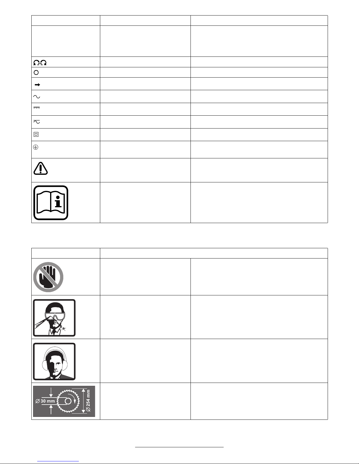
SYMBOLS
Wear protective gloves to avoid injury from the sharp
cutting edges of the saw blade during changing the
saw blade.
Observe the dimensions o f the saw blade. The hole di
ameter must fit the tool spindle without play. Do not
use reducer pieces or adapters.
Observe the maximum allowable speed of the saw
blade.
Saw blades of highly alloyed high speed steel (HSS
steel) are not to be used.
Never use the electrotool without the table insert. Re
place a defective table insert.
Bosch can ensure flawless functioning of the machine
only when original accessories intended for the ma
chine are used.
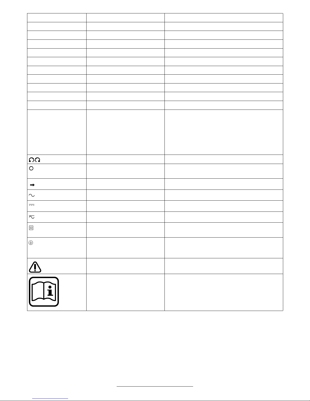
Important notice: Some of the following symbols could have meaning for the use of your tool. Please take note
of the symbols and their meaning. The correct interpretation of the symbols will help you to use the tool in a better
and safer manner.
Symbol Name Meaning
VVolts Voltage
A Amperes Current
Ah Amperehours Capacity, quantity of stored electrical energy
Hz Hertz Frequency (cycles per second)
WWatt Power
Nm Newtonmeter Unit of energy
kg Kilograms Mass, weight
mm Millimetre Length
min/s Minutes/Seconds Time
°C/°F Degrees Celsius/Degrees
Temperature
Fahrenheit
dB Decibel Unit of relative loudness
∅ Diameter Size of drill bits, grinding wheels, etc.
1
min
/n
0
Revolutions per minute/no load
Rotational speed at no load
speed
…/min Revolutions or reciprocation per
minute
0 Off position Zero speed, zero torque...
Revolutions, strokes, surface speed, orbits, etc.
per minute
English–31 609 929 E91 • (04.10) PS
Symbol Name Meaning
SW Wrench width (in mm) Distance between parallel surfaces on fastener el
ements on which the tool must fit on (e.g. hex nuts
or hexhead screws), fit over (e.g. ring wrench) or
fit in (e.g. sockethead screws).
Left rotation/Right rotation Direction of drive rotation
/ Hex socket drive/Square drive Type of tool holder
Arrow Action in the direction of arrow
Alternating current Type or a characteristic of current
Direct current Type or a characteristic of current
Alternating or direct current Type or a characteristic of current
Class II construction Designates double insulated constructed tools
Protection class I
(Grounding terminal)
Warning symbol Alerts user to warning messages.
Warning symbol Provides information for correct handling, e.g.,
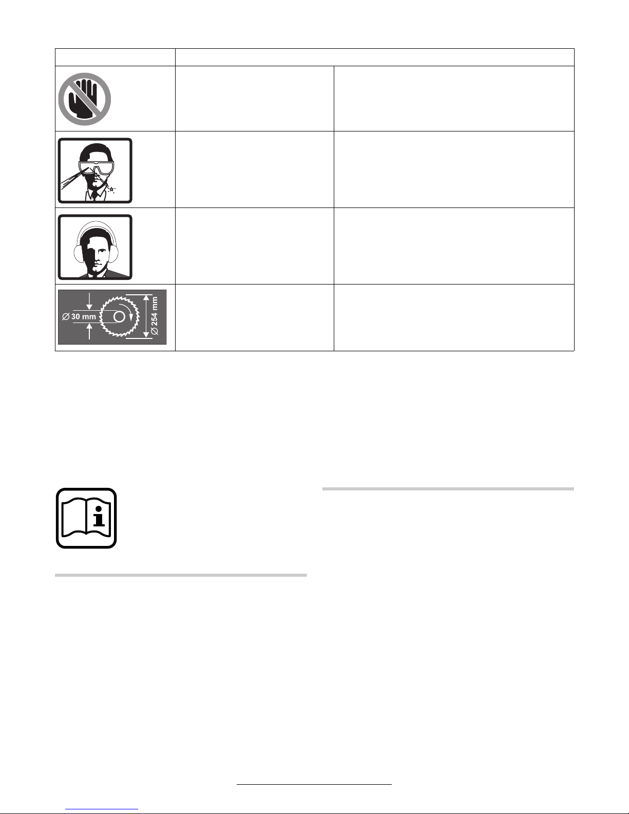
Symbols specifically for this Machine
Symbol Meaning
Warning symbol Danger area! Keep fingers, hands or arms away
Warning symbol Wear protective glasses.
Machines of the protection class I must be ground
ed
Read and understand instructions before opera
tion
read the operating instructions.
from these areas.
Warning symbol Wear hearing protection.
Note symbol Observe the dimensions of the saw blade. The
hole diameter must fit the tool spindle without play.
Do not use reducer pieces or adapters.
English–41 609 929 E91 • (04.10) PS

3 FUNCTION
While reading the operating instruc
tions, refer to the corresponding illus
trations of the electrotool on the front
pages.
Intended Use
The electrotool is intended as a stationary machine for
making straight lengthways and crossways cuts in
wood. Horizontal miter angles of 48° to +48° as well
as vertical bevel angles of 0° to +45° are possible.
Noise/Vibration Information
Measured values are determined according to stan
dard EN 61 029 procedures.
The Aweighted noise levels of the tool are typically:
Sound pressure level: 97 dB(A)
Sound power level: 110 dB(A)
Measurement uncertainty K = 3 dB
Wear ear protection!
The handarm vibration is typically below 2.5 m/s
2
Product Specifications
Compound Mitre Saw GCM 10
PROFESSIONAL
Order number
0 601 B20 …
Rated input power [W] 1 800 1 800 1 650 1 800 1 650 1 650
Voltage [V] 230 220/230 115 230/240 220 120
… 003
… 008
… 032
… 042
…004 … 005 … 006 …014 … 034
.
Frequency [Hz] 50 50/60 50/60 50/60 50/60 60
No load speed [min1] 4 500 4 500 4 500 4 500 4 900 4 500
Tool spindle [mm] 30 25.4 25.4 25.4 30 16
Weight without mains cable [kg] 16.0 16.0 16.0 16.0 16.0 16.0
Saw blade ∅ [Inch] 10 10 10 10 10 10
Protection class / II / II / II / II / II / II
Compound Mitre Saw GCM 10
PROFESSIONAL
Order number
0 601 B20 …
Rated input power [W] 1 800 1 800 1 650 1 800 1 800
Voltage [V] 240 220 110 220/230 220/230
Frequency [Hz] 50 60 50 50 50/60
No load speed [min1] 4 500 4 500 4 500 4 500 4 500
Tool spindle [mm] 25.4 25.4 30 25.4 25.4
Weight without mains cable [kg] 16.0 16.0 16.0 16.0 16.0
Saw blade ∅ [Inch] 10 10 10 10 10
… 037 …040 … 041 … 043 …050
Protection class / II / II / II / II / II
Values apply for the rated voltage [U] of 230/240 V. For
lower voltages and models for specific countries,
these values can vary.
Switchon actions cause brief drops in the mains volt
age. For unfavourable mains conditions, interference
with other equipment can occur.
For mains impedance of less than 0.15 Ω, no interfer
ence can be expected.
For maximum work piece dimensions,
see the Working Instructions Section
English–51 609 929 E91 • (04.10) PS

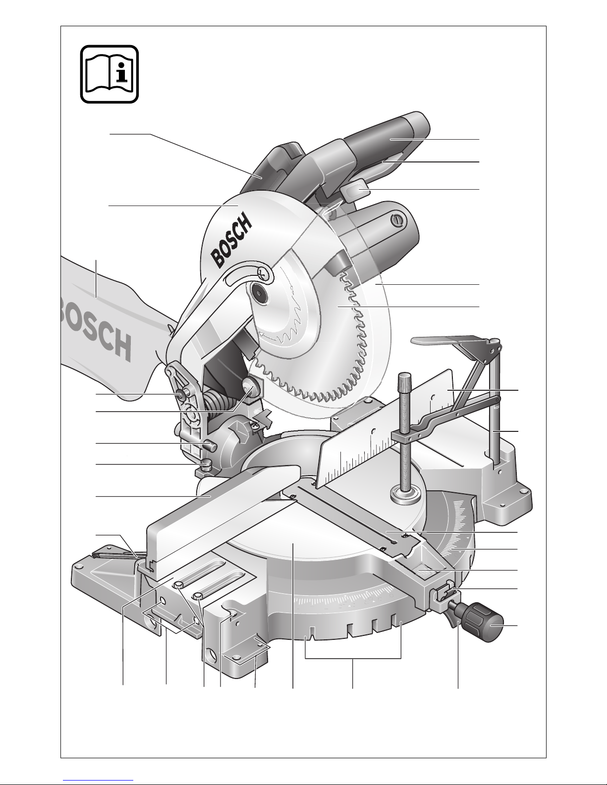
Product Elements
The numbering of the machine elements refers to the
illustrations of the electrotool on the front pages of the
operating instructions.
1 Handle
2 On/Off switch
3 Locking lever
4 Swinging guard
5 Saw blade
6 Fence
7 Quick action clamp
8 Table insert
9 Scale for miter angle (horizontal)
10 Fine scale
11 Locking clamp
12 Locking knob for variable miter angles (horizontal)
13 Lever for miter angle adjustment (horizontal)
14 Detents for standard miter angles
15 Saw table
16 Mounting holes
17 Holes for quick action clamp
18 Sockethead screws (6 mm) of the saw table ex
tension
19 Holes for extension hoop
20 Saw table extension
21 Allen key (6 mm) / Phillips screwdriver
22 Fence extension
23 Stop bolt for 33,9° bevel angle (vertical)
24 Pin of the setting knob for 33.9° bevel angle
(vertical)
25 Roller
*
26 Transport locking pin
27 Dust bag
28 Protective hood
29 Transport handle
30 Clamping lever for fence extension
31 Setting knob for 33.9° bevel angle (vertical)
32 Clamping handle for variable bevel angle (vertical)
33 Elongated hole
34 Sawdust ejector
35 Sockethead screws (6 mm) of the fence
36 Ring/openended wrench (ring: 13 mm; open
ended: 12 mm)
37 Phillips screw (attachment of the swinging guard)
38 Spindle lock
39 Hexhead bolt for attaching the saw blade
40 Clamping flange
41 Tool spindle
42 Length stop
43 Extension hoop
44 Clamping lever of the quick action clamp
45 Threaded rod of the quick action clamp
46 Screws of the table insert
47 Angle indicator (vertical)
Not all the accessories illustrated or described are in
cluded in standard delivery.
Not included for the tool executions:
*
0 601 B20 004, … 005, … 006, … 034, … 037,
… 040, … 043, … 050.
The swinging guard 4 cannot be locked. Perform the
operations described in the following accordingly with
out the locking lever 3.
English–61 609 929 E91 • (04.10) PS
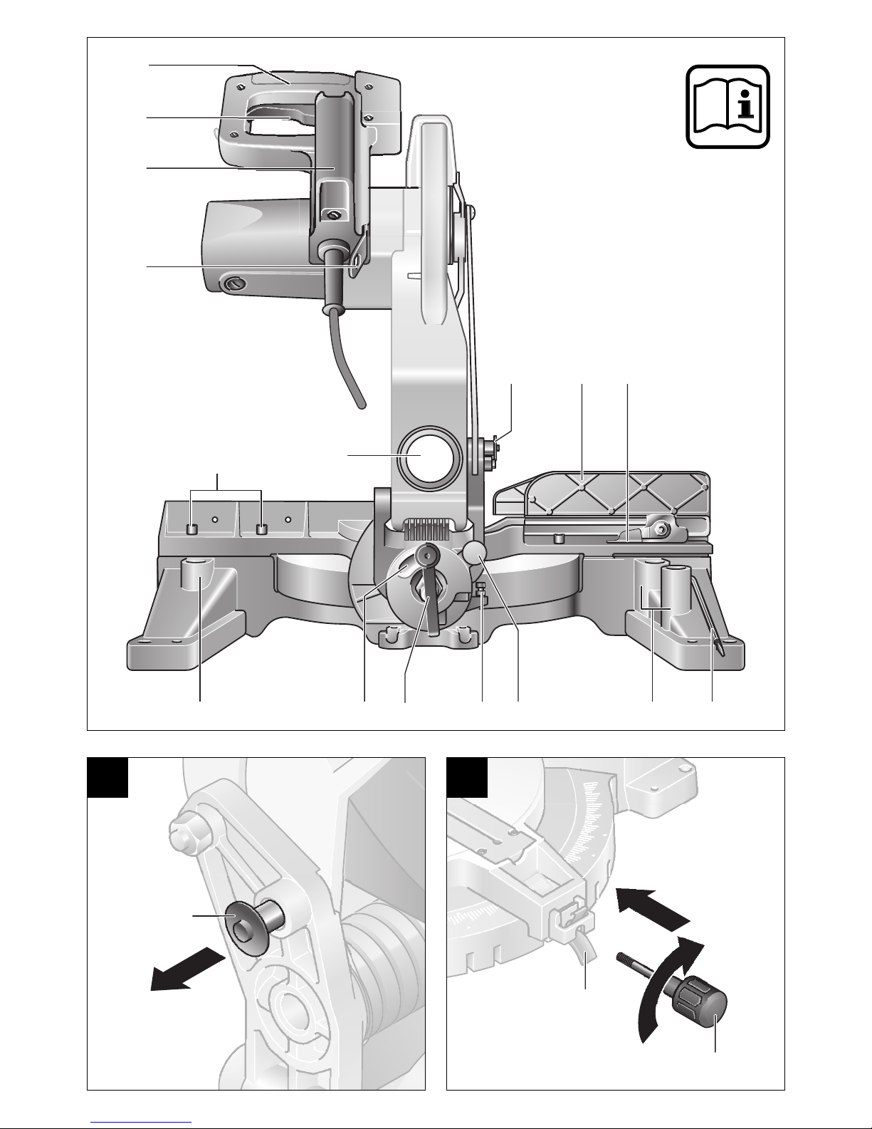
4 OPERATING INSTRUCTIONS
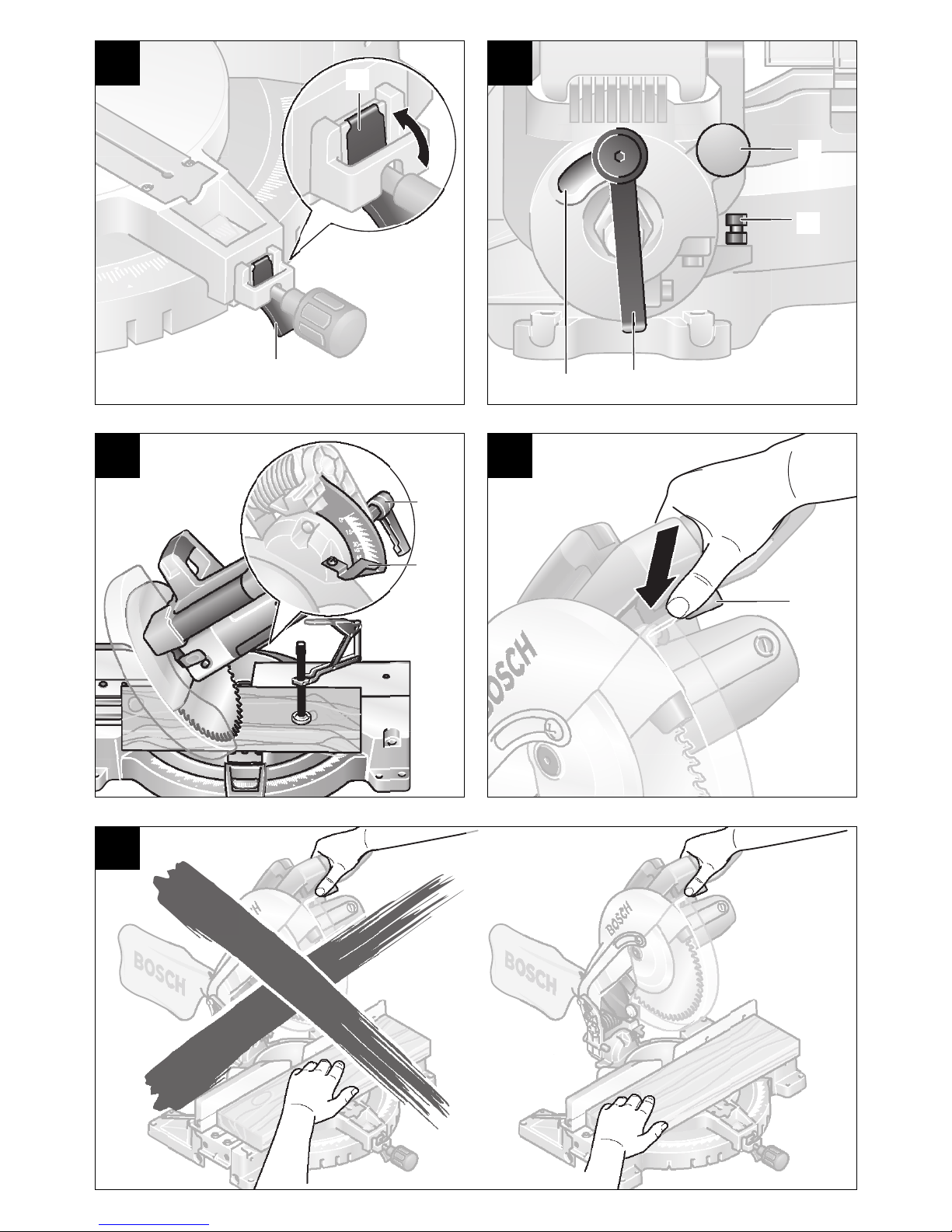
Transport Safety
(see Figure )
Before all work on the machine, pull the power
plug.
The transport locking pin 26 makes possible easy han
dling of the machine when transporting to the various
working locations.
Securing the Machine (Transport Position)
Press the locking lever 3 (also see the illustration )
and, at the same time, swing the tool arm down with
the handle 1 to the stop.
Press in the transport safety 26 and release the han
dle.
Releasing the Machine (Working Position)
Press the tool arm with the handle 1 downward some
what to relieve the load on the transport locking pin.
Pull the transport safety 26 completely outward.
Guide the tool arm slowly upward.
A
N
Mounting the Locking Knob
(see Figure )
Screw the locking knob 12 into the hole above the le
ver 13.
Do not tighten the knob too firmly.
B
Changing the Tool
Before all work on the machine, pull the power
plug.
Use only sharp, flawless saw blades. Change
cracked, bent or dull saw blades without delay.
Use only saw blades that comply with the characteris
tic data given in these operating instructions and have
been tested according to EN 8471 and appropriately
marked.
Use only saw blades whose allowable rotational speed
is as least as high as the noload speed of the electro
tool.
Actuate the spindle lock only when the saw blade is at
a standstill.
The saw blade becomes very hot while working; do
not take hold of it until it has cooled.
Wear protective gloves to avoid injury from the sharp
cutting edges of the saw blade during changing the
saw blade.
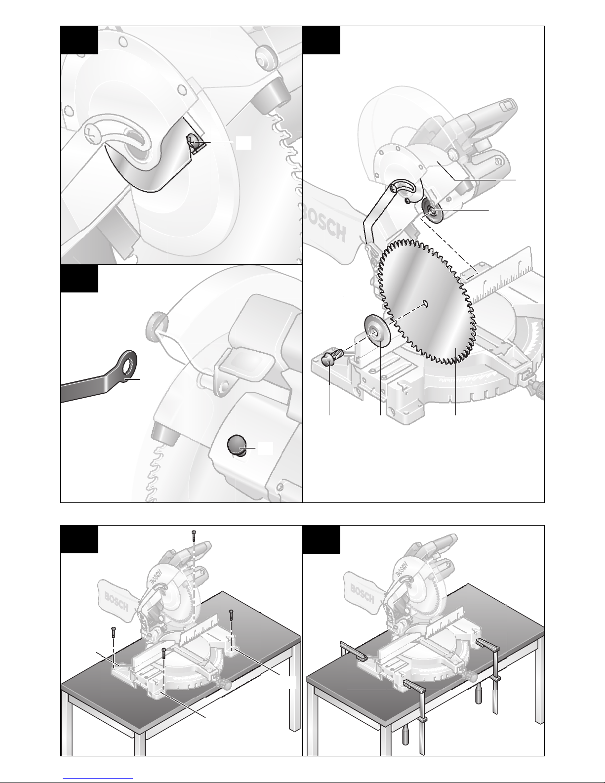
Removing the Saw Blade
Place the machine in the working position.
Press the locking lever 3 (also see Figure ) and
swing the swinging guard 4 to the rear to the stop.
Hold the swinging guard in this position.
Loosen the screw 37 with a commercially available
Phillips screwdriver (Caution: Spring loaded!). Do
not unscrew the screw completely. (see Figure ).
Pull the swinging guard completely to the rear until it is
held with the pin of the locking lever 3.
Turn the hexhead bolt 39 with the ring wrench 36
(SW 13) provided while pressing the spindle lock 38 at
the same time until it engages. (see the illustration )
Hold the spindle lock depressed and screw out the
hexhead bolt 39 in the clockwise direction (lefthand
threads!). Take off the clamping flange 40. Remove
the saw blade 5. (see Figure )
Mounting the Saw Blade
If necessary, clean all parts to be mounted.
Place the new saw blade on the tool spindle 41.
(see Figure )
Place on the clamping flange 40 and insert the hex
head bolt 39. Press the spindle lock 38 until it engag
es and tighten the hexhead screw 39 in the counter
clockwise direction with a torque of approx. 15 23
Nm.
Press the swinging guard 4 down at the front until the
screw 37 engages in the cutout. It may be necessary
to hold the tool arm by the handle to achieve the spring
loading of the swinging guard.
Retighten the screw 37.
Guide the swinging guard slowly downward until the
pin of the locking lever 3 behind the swinging guard
audibly engages.
C3
Take care during the mounting that the
cutting direction of the teeth (direction of
the arrow on the saw blade) agrees with
the direction of the arrow on the swinging
guard!
C3
N
C1
C2
Stationary or Flexible Mounting
To ensure safe handling, the electrotool
must be mounted on a flat and stabile
working surface (e.g., workbench).
Stationary Mounting
(see Figure )
Attach the electrotool with suitable screw fasteners to
the working surface. The holes 16 serve for this pur
pose.
D1
English–71 609 929 E91 • (04.10) PS
Flexible Mounting
(see Figure )
Clamp the electrotool with commercially available
screw clamps by the feet to the working surface.
D2
Dust/Chip Extraction
Dust is generated while working that can be det
rimental to health, inflammable or explosive.
Suitable protective measure are required.
For example: Some types of dust are considered
to be carcinogenic. Use suitable dust vacuuming
and wear a dust protection mask.
Integrated Dust Extraction
(see Figure )
Press the clamp on the dust bag 27 together and slide
the dust bag over the sawdust ejector 34. The clamp
must engage in the groove on the sawdust ejector.
Release the clamp on the dust bag.
The dust bag must never come in contact with moving
parts of the machine while sawing.
Empty the dust bag in a timely manner.
External Dust Extraction
Use a suitable adapter from the Bosch accessory pro
gram to connect a vacuum cleaner to the sawdust
ejector 34. Firmly attach the adapter and vacuum
cleaner hose.
The vacuum cleaner must be suitable for the material
to be worked.
When vacuuming dry dust that is especially detrimen
tal to health or carcinogenic, use a special vacuum
cleaner.
E
Extending the Fence
(see Figure )
Before all work on the machine, pull the power
plug.
For vertical bevel angle sawing, the fence must be re
positioned.
Loosen the clamping lever 30 and pull the fence exten
sion 22 completely out.
Reclamp with the clamping lever.
F
Ensure when extending or enlarging the
fence that the functionality of the electro
tool (especially of the swinging guard) is
not restricted.
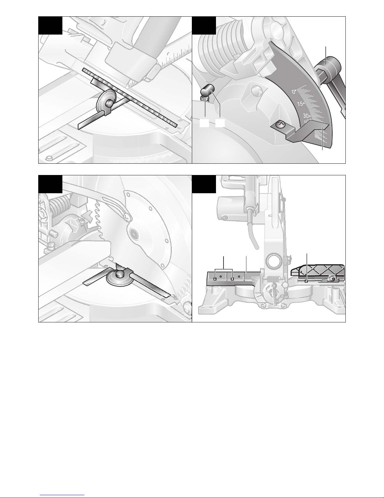
Extending the Saw Table
Before all work on the machine, pull the power
plug.
Saw Table Extension
(see Figure )
Long work pieces must be supported at the free end.
Loosen the two sockethead screws 18 with the Allen
key 21 (6 mm) provided.
Pull out the saw table extension 20 to the stop and
retighten the sockethead screws.
Extension Hoop
(see Figure )
Slide the extension hoop 43 on either side of the elec
trotool to the desired length into the holes 19 provid
ed for this purpose.
Use the stop 42 to saw off work pieces of equal
lengths.
G
H
Clamping the Work Piece
(see Figure )
Before all work on the machine, pull the power
plug.
To ensure optimum working safety, the work piece
must always be firmly clamped.
Do not work with work pieces that are too small to
clamp.
Press the work piece firmly against the fence 6 and the
fence extension 22.
Insert the quick action clamp 7 provided into one of the
holes 17 intended for it. Adapt the quick action clamp
to the work piece by twisting the threaded rod 45.
Press the clamping lever 44 and thereby firmly clamp
the work piece.
I
When clamping the work piece, do not
reach with the fingers under the clamping
lever of the quick action clamp.
Adjusting the Miter Angle
Before all work on the machine, pull the power
plug.
To ensure precise cuts, the basic adjustments of the
electrotool must be checked and adjusted as neces
sary after intensive use (see Section „Checking and
Adjusting Basic Adjustment“).
English–81 609 929 E91 • (04.10) PS
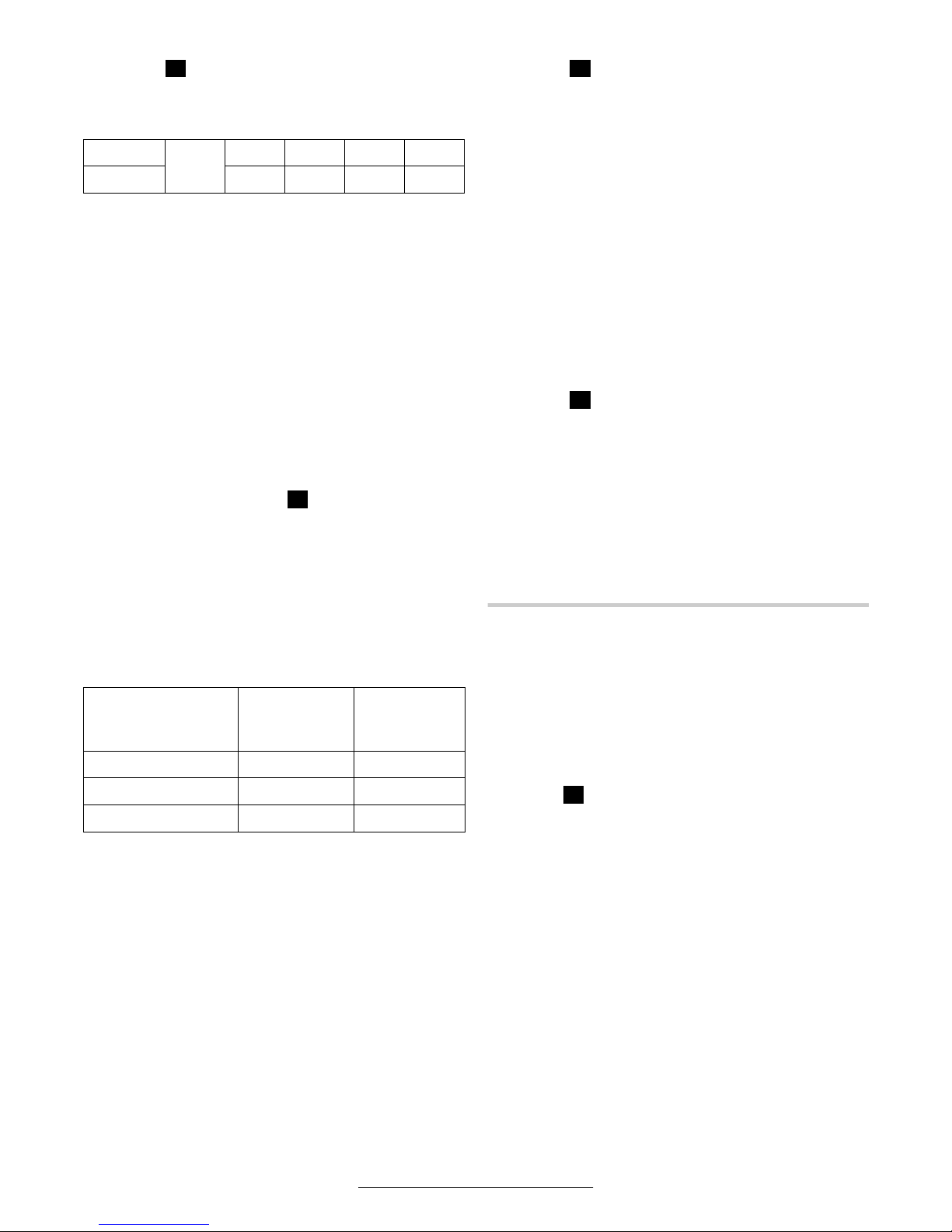
Standard Horizontal Miter Angles
(see Figure )
J
For quick and precise setting of often used miter an
gles, detents 14 are provided on the saw table:
Left
15° 22,5° 31,6° 45°
0°
Right 15° 22,5° 31,6° 45°
Place the machine in the working position.
Loosen the locking knob 12 in case it is tightened.
Pull the lever 13 and turn the saw table 15 to the de
sired miter angle to the right or the left. Release the le
ver. The lever must be felt to engage in the detent.
Variable Horizontal Miter Angle
The horizontal miter angle can be set in the range from
48° (left side) to 48° (right side).
Place the machine in the working position.
Loosen the locking knob 12 in case it is tightened.
Pull the lever 13 and press the locking clamp 11 at the
same time until it engages in the groove provide for this
purpose (see the illustration ). In this manner, the
K
saw table becomes freely moveable.
Rotate the saw table 15 to the left or right and set the
desired miter angle with the aid of the fine scale 10.
Retighten the locking knob 12.
Standard Vertical Bevel Angles
(see Figure )
L
For quick and precise setting of often used bevel an
gles, stops are provided for the angles of 0°, 33.9° and
45°.
Place the machine in the working position.
Loosen the clamping handle 32.
For the standard angles of 0° or 45°, swing the tool
arm with the handle 1 to the stop at the upper or the
lower end of the elongated hole 33.
For the standard angle of 33.9°, press the setting knob
31 completely in. Then swing the tool arm with the
handle 1 until the pin 24 rests against the stop bolt 23.
Retighten the clamping handle 32.
Variable Vertical Bevel Angle
(see Figure )
M
The vertical bevel angle can be set in the range from
0° to 45°.
Loosen the clamping handle 32.
Swing the tool arm with the handle 1 until the angle in
dicator 47 points to the desired bevel angle.
Hold the tool arm in this position and retighten the
clamping handle 32.
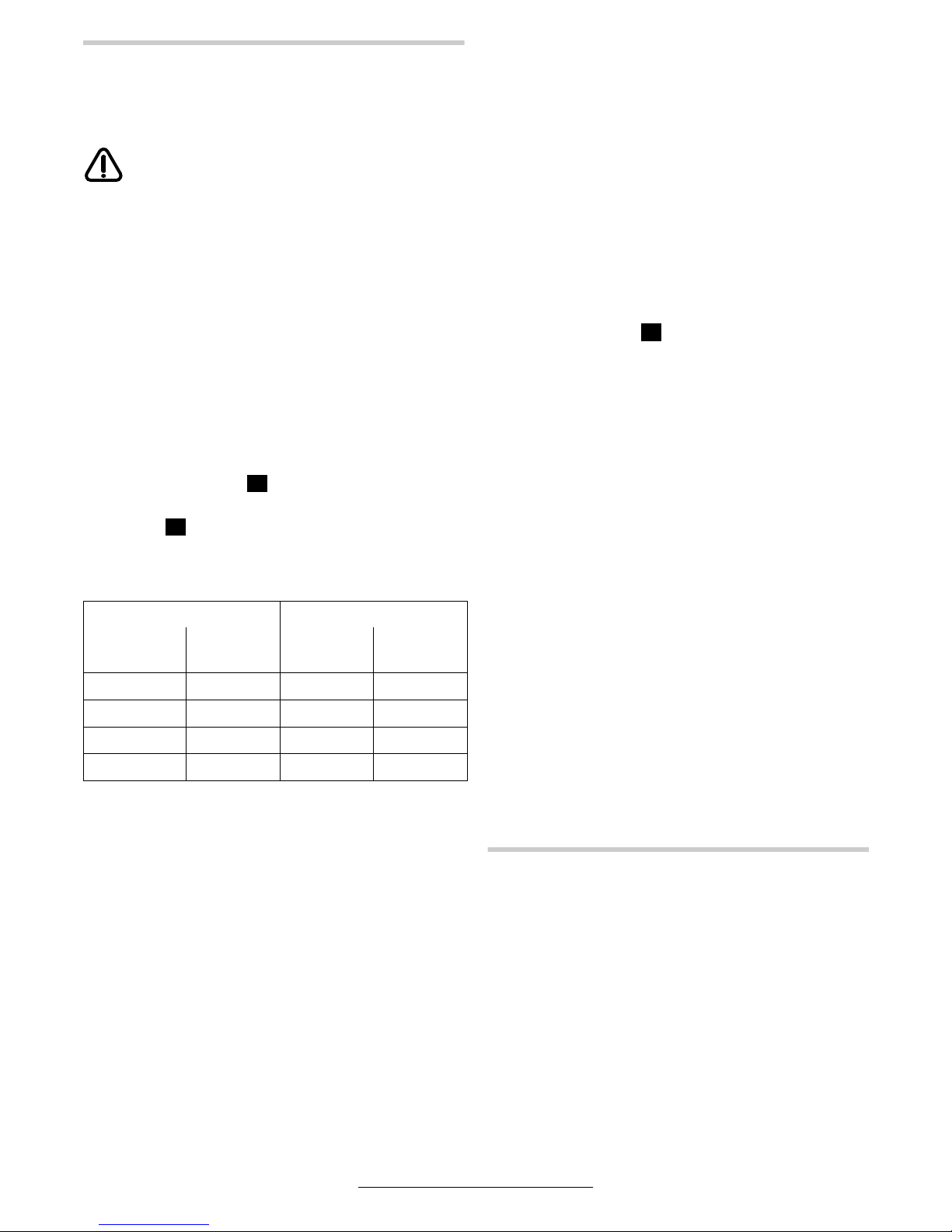
Fine scale
With the fine scale 10, the horizontal miter angle can
be set with an accuracy of up to ¼°.
Desired Setting of
the Initial Angle x
Align the Fine
Scale Mark
... with the
Mark (Scale 9)
(Scale 10)
x,25 ° ¼° x + 1°
x,5 ° ½° x + 2°
x,75 ° ¾° x + 3°
Example:
To set to a miter angle of 40.5°, the ½° mark of the fine
scale 10 must be aligned with the 42° mark of the
scale 9.
Putting into Operation
Switching On and Off
To put into operation, pull the on/off switch 2 in the
direction of the handle 1.
For safety reasons, the on/off switch of the ma
chine cannot be locked on but must remain de
pressed during operation.
For sawing, press in addition the locking lever 3. (see
the Figure
Only by pressing the locking lever can the tool arm be
guided downward.
To switch off the machine, release the on/off switch
2.
0 601 B20 037 (Australia)
To put into operation, slide the switch lock in the di
rection of the tool arm. Then press the on/off switch 2
and hold it depressed.
For safety reasons, the on/off switch of the ma
chine cannot be locked on but must remain de
pressed during operation.
To switch off the machine, release the on/off switch
2.
N
)
English–91 609 929 E91 • (04.10) PS
Working Instructions
Before all work on the machine, pull the power
plug.
General Sawing Instruction
For all cuts, it must first be ensured that
the saw blade at no time can come in con
tact with the fence, screw clamp or other
machine parts. Remove possible interfer
ing auxiliary stops or adjust them accord
ingly.
Do not load the machine so heavily that it comes to a
standstill.
Advancing that is too fast reduces considerably the
performance capability of the electrotool and reduces
the service life of the saw blade.
Use only sharp saw blades that are suitab le for the ma
terial being worked.
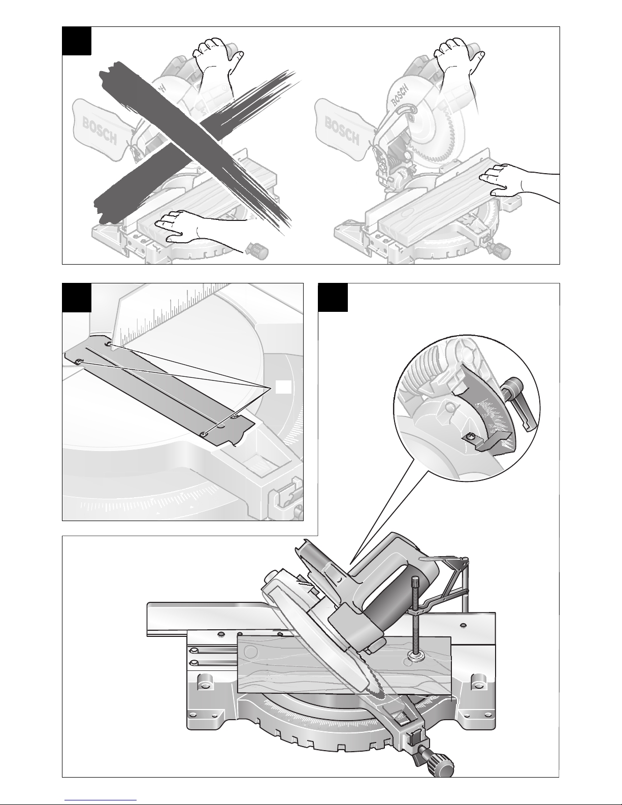
Hand Positioning
Keep fingers, hands and arms away from the rotating
saw blade. (see Figure )
Do not cross your arms when operating the tool arm.
(see Figure )
P
O
Special Work Pieces
When sawing curved or round work pieces, they must
be especially secured against slipping. At the cutting
line, no gap may exist between the work piece and the
fence or saw table.
In case necessary, a special fixture must be fabricated.
Table Insert
The red table insert 8 can become worn after long us
age of the electrotool.
Replace a defective table insert.
Place the electrotool in the working position.
Unscrew the screws 46 with the Phillips screwdriver
provided. (see Figure )
Insert the new table insert 8 and screw in all screws 46
again.
Set the vertical bevel angle to 0° and saw a slot in the
table insert.
Then set the vertical bevel angle to 45° and again saw
into the slot. With this procedure, it is ensured that the
table insert is as close as possible to the teeth of the
saw blade without coming in contact with them.
Q
Maximum Work Piece Dimensions
Sawing Angle Height x Width [mm]
Miter
(Horizontal)
0° 0° 89 x 95 61 x 144
45° 0° 89 x 67 61 x 101
0° 45° 46 x 105 35 x 144
45° 45° 46 x 95 30 x 99
Cut-off Sawing
Clamp the work piece firmly according to its dimen
sions.
Set the desired miter angle.
Switch on the electrotool.
Press the locking lever 3 and guide the tool arm with
the handle 1 slowly downward.
Saw through the work piece with uniform advancing.
Switch off the electrotool and wait until the saw blade
has come to a complete standstill.
Guide the tool arm slowly upward.
Bevel
(Vertical)
At Max.
Height
At Max.
Width
Working with Profile Moldings
(Floor or Ceiling Moldings)
Profile moldings can be work with two different meth
ods:
– Placed against the fence,
– Lying flat on the saw table.
Always make trial cuts with the miter angle settings
first on scrap wood.
English–101 609 929 E91 • (04.10) PS
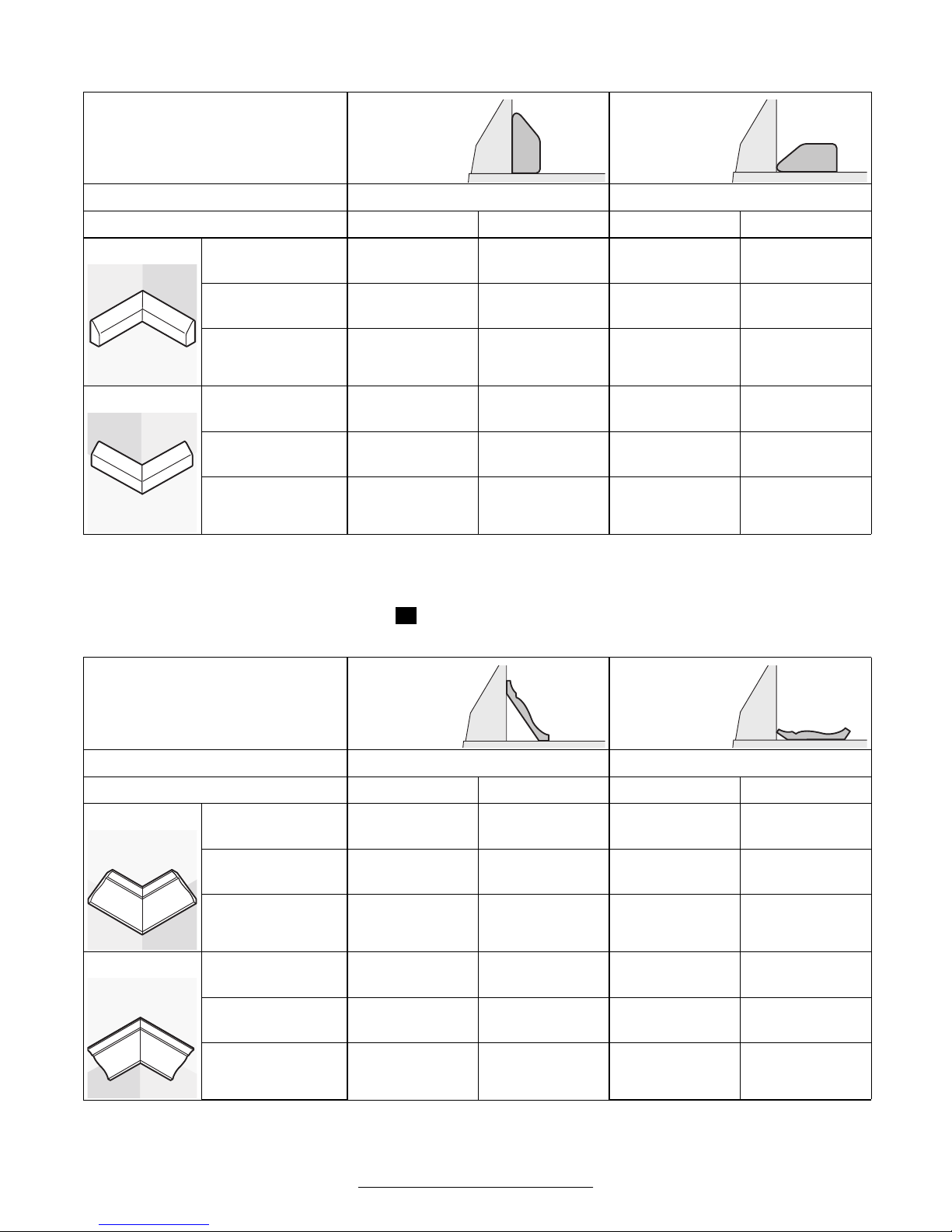
Floor Moldings
The following table contains instructions for the working of floor moldings.
Setting Placed
Against the
Fence
Lying Flat
on the Saw
Table
Vertical Bevel Angle 0° 45°
Floor Molding Left Side Right Side Left Side Right Side
Inner Corner Horizontal Miter
Angle
Positioning of the
Work Piece
The finished work
piece is located …
Outer Corner Horizontal Miter
Angle
Positioning of the
Work Piece
The finished work
piece is located …
45° Left 45° Right 0° 0°
Lower edge on
the saw table
…
to the left of
the cut
Lower edge on
the saw table
…
to the right of
the cut
Upper edge on
the fence
…
to the left of
the cut
45° Right 45° Left 0° 0°
Lower edge on
the saw table
…
to the right of
the cut
Lower edge on
the saw table
…
to the left of
the cut
Lower edge on
the fence
…
to the right of
the cut
…
Lower edge on
the fence
…
to the left of
the cut
Upper edge on
the fence
to the right of
the cut
Ceiling Molding (According to US Standard)
When the ceiling molding is to be work lying flat on the saw table, the standard miter angle of 31.6° (horizontal)
and 33.9° (vertical) must be set. (see Figure )
R
The following table contains instructions for the working of ceiling moldings.
Setting Placed
Against the
Fence
Lying Flat
on the Saw
Table
Vertical Bevel Angle 0° 33,9°
Ceiling Molding Left Side Right Side Left Side Right Side
Inner Corner Horizontal Miter
Angle
Positioning of the
Work Piece
The finished work
piece is located …
Outer Corner Horizontal Miter
Angle
Positioning of the
Work Piece
45° Right 45° Left 31.6° Right 31.6° Left
Lower edge on
the fence
…
to the right of
the cut
Lower edge on
the fence
…
to the left of
the cut
Upper edge on
the fence
…
to the left of
the cut
Lower edge on
the fence
…
to the left of
45° Left 45° Right 31.6° Left 31.6° Right
Lower edge on
the fence
Lower edge on
the fence
Lower edge on
the fence
Upper edge on
the fence
the cut
The finished work
piece is located …
…
to the right of
the cut
…
to the left of
the cut
…
to the right of
the cut
…
to the right of
the cut
English–111 609 929 E91 • (04.10) PS

Checking and Adjusting Basic Adjustment
Before all work on the machine, pull the power
plug.
To ensure precise cuts, the basic adjustment must be
checked and adjusted as necessary after intensive us
age.
Bevel Angle 33,9° (Vertical)
Place the machine in the working position.
Rotate the saw table 15 to the detent 14 for 0°. Loos
en the clamping lever 30 and pull the fence extension
22 completely out.
Loosen the clamping handle 32 and press the setting
knob 31 completely in. Swing the tool arm with the
handle 1 until the pin 24 rests against the stop bolt 23.
Checking: (see Figure
Place a combination square set to 33,9° on the saw
table 15. The leg of the square must be flush with the
saw blade over its entire length.
Adjusting: (see Figure )
Loosen the locking nut of the stop bolt 23 with the
openended wrench 36 (12 mm) provided. Turn the
stop bolt either in or out until the leg of the square is
flush with the saw blade over its entire length.
Retighten the clamping handle 32. Then retighten the
locking nut of the stop screw 23.
S1
)
S2
Fence
Place the electrotool in the transport position.
Rotate the saw table 15 to the detent 14 for 0°. Loos
en the clamping lever 30 and pull the fence extension
22 completely out.
Checking: (see Figure
Set the combination square to 90° and place it on the
saw table 15. The square must be flush with the fence
6 over its entire length.
Adjusting: (see Figure
Loosen all three sockethead screws 35 with the Allen
key 21 (6 mm) provided. Rotate the fence 6 until the
square is flush with the fence over its entire length. Re
tighten the sockethead screws.
T1
)
T2
)
5 MAINTENANCE AND SERVICE
Maintenance
Before all work on the machine, pull the power
plug.
Always keep the machine and the ventilation slits clean
for efficient and safe working.
The swinging guard must always be able to move free
ly and close by itself. Therefore, always keep the area
around the swinging guard clean.
Remove dust and chips by blowing out with com
pressed air or with a brush.
Clean the roller 25 regularly.
Should the tool fail in spite of careful manufacturing
and testing procedures, have the repairs performed by
an authorized customer service location for Bosch
ElectroTools.
For inquiries and spare parts ordering, please include
the 10digit order number on the nameplate of the
tool.
Accessories
Saw blade 254 x 30 mm, 40 teeth. . . 2 608 640 438
Saw blade 254 x 25,4 mm, 40 teeth . 2 608 640 459
Saw blade 254 x 16 mm, 40 teeth. . . 2 608 640 466
Saw blade 254 x 25,4 mm, 120 teeth 2 608 640 465
Quick action clamp . . . . . . . . . . . . . . 2 608 040 205
Table insert . . . . . . . . . . . . . . . . . . . . 2 607 960 014
Dust bag . . . . . . . . . . . . . . . . . . . . . . 2 605 411 187
Extension hoop (356 mm) . . . . . . . . . 2 607 001 911
Angle adapter for dust bag . . . . . . . . 2 608 601 171
Vacuuming adapter for 35 mm hose . 2 605 702 022
Carrying bag . . . . . . . . . . . . . . . . . . . 2 605 435 019
Disposal
Tool, accessories and packaging should be sorted for
environmentfriendly recycling.
The plastic components are labeled for categorized re
cycling.
English–121 609 929 E91 • (04.10) PS

Service and Customer Advice
Exploded views and information on spare parts can be
found under: www.boschpt.com
In case of a claim, repair or purchase of replacement
parts or in case of queries or other problems please
contact your local dealer or Bosch representative.
People’s Republic of China
Website: www.boschpt.com.cn
Toll Free hotline:
Sole Agent:
Melchers (H.K.) Ltd.
Hong Kong Representative Office:
Room 1210, Shun Tak Centre, WestTower,
168 – 200 Connaught Road, Central Hong Kong
Customer Service Hotline:
. . . . . . . . . . . . . . . . . . . . . . . . . . . . . . . +852 25 48 79 14
Fax
EMail: bosch@melchers.com.hk
Guangzhou Representative Office:
Room 1108, T. P. Plaza,
9/109 Liu Hua Road,
Guangzhou, P.R. China
. . . . . . . . . . . . . . . . . . . . . 800 8 20 84 84
. . . . . . . . +852 25 89 15 61
. . . . . . . . . . . . . . . . . . . . . . . . . . . . . . . +86 20 86 66 87 00
. . . . . . . . . . . . . . . . . . . . . . . . . . . . . +86 20 86 67 78 45
Fax
Postal code: 510010
EMail: bosch@gz.melchers.com.cn
Bosch After-sales Service Centre
Guangzhou:
1/F, East Wing, No. 4 Zeng Cha Road,
Guangzhou, P.R. China
. . . . . . . . . . . . . . . . . . . . . . . . . . . . . . . +86 20 81 75 84 67
. . . . . . . . . . . . . . . . . . . . . . . . . . . . . . . +86 20 81 75 88 73
. . . . . . . . . . . . . . . . . . . . . . . . . . . . . +86 20 81 75 71 69
Fax
Postal code: 510165
EMail: bsc@gz.melchers.com.cn
Shanghai Representative Office:
13 Floor, East Ocean Centre,
No. 588 Yanan Road (East),
Shanghai, P.R. China
. . . . . . . . . . . . . . . . . . . . . . . . . . . . . . . +86 21 63 52 88 48
. . . . . . . . . . . . . . . . . . . . . . . . . . . . . +86 21 63 51 31 38
Fax
Postal code: 200001
EMail: boschew@sh.melchers.com.cn
Beijing Representative Office:
Room 503 – 504, Beijing Tower,
No. 10 Changan Ave (East)
Beijing, P.R. China
. . . . . . . . . . . . . . . . . . . . . . . . . . . . . . . +86 10 65 25 77 75
. . . . . . . . . . . . . . . . . . . . . . . . . . . . . . +86 10 65 12 35 05
Fax
Postal code: 100006
EMail: bosch@bj.melchers.com.cn
Bosch After-sales Service Centre Beijing:
Room 102 – 103, Beijing Liuliqiao Lanjinglijia,
No. 10 Xisanhuan South Road, Fengtai District,
Beijing, P.R. China
. . . . . . . . . . . . . . . . . . . . . . . . . . . . . . . +86 10 63 36 77 75
. . . . . . . . . . . . . . . . . . . . . . . . . . . . . . . +86 10 63 36 77 76
. . . . . . . . . . . . . . . . . . . . . . . . . . . . . . +86 10 63 36 77 71
Fax
Postal code: 100073
EMail: boschservice@bj.melchers.com.cn
Chongqing Representative Office:
Room 1804,Metropolitan Tower,
68 Zourong Road, Yuzhong District,
Chongqing, P.R. China
. . . . . . . . . . . . . . . . . . . . . . . . . . . . . . . +86 23 63 82 80 40
. . . . . . . . . . . . . . . . . . . . . . . . . . . . . . . +86 23 63 82 80 41
. . . . . . . . . . . . . . . . . . . . . . . . . . . . . . +86 23 63 82 80 43
Fax
Postal code: 400010
EMail: bosch@cq.melchers.com.cn
Bosch After-sales Service Centre
Chongqing:
16611 Yuzhou Road, Gaoxin District,
Chongqing, P.R. China
. . . . . . . . . . . . . . . . . . . . . . . +86 23 68 57 91 93
Fax . . . . . . . . . . . . . . . . . . . . . . +86 23 68 57 90 23
Postal code: 400041
EMail: bsc@cq.melchers.com.cn
Wuhan Representative Office:
Rm 202, Unit C, Apartment Bldg.
Yangtze Hotel,1131 Liberation Ave,
Wuhan, P.R. China
. . . . . . . . . . . . . . . . . . . . . . . +86 27 83 63 78 85
Fax . . . . . . . . . . . . . . . . . . . . . . +86 27 83 62 32 96
Postal code: 430030
EMail: bosch@wh.melchers.com.cn
Bosch After-sales Service Centre Shanghai:
East Four First Floor Building A,
No. 357 Zhaohua Road,
Shanghai, P.R. China
. . . . . . . . . . . . . . . . . . . . . . . . . . . . . . . +86 21 62 51 13 57
. . . . . . . . . . . . . . . . . . . . . . . . . . . . . +86 21 62 51 07 60
Fax
Postal code: 200050
EMail: boschservice@sh.melchers.com.cn
Wuhan After-sales Service Centre:
160 Aomen Road, Jiang’an District,
Hankou, Wuhan, P.R. China
. . . . . . . . . . . . . . . . . . . . . . . +86 27 82 44 81 57
Fax . . . . . . . . . . . . . . . . . . . . . . +86 27 82 44 81 60
Postal code: 430015
EMail: boschservice@wh.melchers.com.cn
English–131 609 929 E91 • (04.10) PS

Indonesia
P. T. Multi Tehaka
Karang Anyar Permai Block B24
Jl. Karang Anyar No. 55
Jakarta Pusat 10740
Indonesia
. . . . . . . . . . . . . . . . . . . . . . . +62 21 6 59 52 22 (5 lines)
. . . . . . . . . . . . . . . . . . . . . . . . . . . +62 21 6 59 52 52 3
Fax
sales@bosch.co.id
www.bosch.co.id
Phillippines
Robert Bosch, Inc.
Zuellig Building
Sen. Gil Puyat Avenue
Makati City 1200, Metro Manila
Philippines
. . . . . . . . . . . . . . . . . . . . . . . . . . . . . . . . +63 2 8 17 32 31
www.bosch.com.ph
Singapore
Robert Bosch (SEA.) Pte. Ltd.
38 C Jalan Pemimpin
Singapore 915701
Republic of Singapore
. . . . . . . . . . . . . . . . . . . . . . . . . . . . . . . . . . +65 3 50 54 94
. . . . . . . . . . . . . . . . . . . . . . . . . . . . . . . . . . +65 3 50 53 27
Fax
www.bosch.com.sg
Vietnam
Ho Chi Minh City
Robert Bosch (SEA) Pte Ltd
Resident Representative Office HCMC
Tacasin Business Centre, 2nd Floor
243243B Hoang Van Thu P.1
Tan Binh District
Vietnam
. . . . . . . . . . . . . . . . . . . . . . . . . . . . . . . . +84 8 8 47 87 64
. . . . . . . . . . . . . . . . . . . . . . . . . . . . . . . . +84 8 8 47 83 28
Fax
Malaysia
Robert Bosch (SEA.) Pte. Ltd.
No. 8a, Jalan 13/6
Selangor Darul Ehsan
Petaling Jaya 46200
Malaysia
. . . . . . . . . . . . . . . . . . . . . . . . . . . . . . . +60 3 79 58 30 00
Fax (EW Dept.)
www.bosch.com.sg
Thailand
Robert Bosch Ltd.
Liberty Square Building
No. 287, 11 Floor
Silom Road, Bangrak
Bangkok 10500
. . . . . . . . . . . . . . . . . . . +60 3 79 58 38 38
. . . . . . . . . . . . . . . +66 2 6 31 18 79 18 88 (10 lines)
. . . . . . . . . . . . . . . . . . . . . . . . . . . . . . . . +66 2 2 38 47 83
Fax
Robert Bosch Ltd., P. O. Box 2054
Bangkok 10501, Thailand
Bosch Service Training Centre
28692869/1 Soi Ban Kluay
Rama IV Road (near old Paknam Railway)
Prakanong District
10110 Bangkok
Thailand
. . . . . . . . . . . . . . . . . . . . . . . . . . . . . +66 2 6 71 78 00 4
. . . . . . . . . . . . . . . . . . . . . . . . . . . . . . . . +66 2 2 49 42 96
Fax
. . . . . . . . . . . . . . . . . . . . . . . . . . . . . . . . +66 2 2 49 52 99
Fax
Australia
Robert Bosch Australia L.t.d.
RBAU/SPT2
1555 Centre Road
P.O. Box 66 Clayton
3168 Clayton/Victoria
. . . . . . . . . . . . . . . . . . . . . . . . . . . . . . . . . . . 1 8 00 80 47 77
. . . . . . . . . . . . . . . . . . . . . . . . . . . . . . . . . . 1 8 00 81 95 20
Fax
CustomerSupportSPT@au.bosch.com
www.bosch.com.au
Specifications subject to change without notice.
Argentina
RBAR
. . . . . . . . . . . . . . . . . . . . . . . . . . . 0810 555 2020
Bolivia
HANSA
. . . . . . . . . . . . . . . . . . . . . . . . . . +59 12 314 445
Brasil
RBLA
. . . . . . . . . . . . . . . . . . . . . . . . . . 0800 70 45 446
Chile
EMASA
. . . . . . . . . . . . . . . . . . . . . . . . . . . 600 7378 4832
Colômbia
INNOVATEQ
. . . . . . . . . . . . . . . . . . . . . . . . . . .+571 629 4284
Costa Rica
MADISA
English–141 609 929 E91 • (04.10) PS

. . . . . . . . . . . . . . . . . . . . . . . . . . .+506 233 6255
Equador
ELECTRO DIESEL
. . . . . . . . . . . . . . . . . . . . . . . . . +593 4 220 2688
El Salvador
PROYESA
. . . . . . . . . . . . . . . . . . . . . . . . . . .+503 221 0666
Guatelmala
EDISA
. . . . . . . . . . . . . . . . . . . . . . . . . +502 2 331 7227
Honduras
CHIPS
. . . . . . . . . . . . . . . . . . . . . . . . . . .+504 556 9781
México
RBMX
. . . . . . . . . . . . . . . . . . . . . . . . . . .+55 5284 3000
Paraguai
CHISPA
. . . . . . . . . . . . . . . . . . . . . . . . . +595 21 553 315
Peru
AUTOREX
. . . . . . . . . . . . . . . . . . . . . . . . . . +51 1 475 5453
Venezuela
RBVE
. . . . . . . . . . . . . . . . . . . . . . . . +58 212 207 4511
Specifications subject to change without notice.
English–151 609 929 E91 • (04.10) PS

1 INSTRUCCIONES GENERALES DE SEGURIDAD
PARA HERRAMIENTAS ELÉCTRICAS
ADVERTENCIA
ciones de seguridad siguientes, ello puede dar lugar a
una descarga eléctrica, incendio o lesión seria.
¡Conserve estas instrucciones advertencia en un
lugar seguro!
Puesto de trabajo
Mantenga limpio y bien iluminado su puesto de
trabajo. El desorden y una iluminación deficiente en
las áreas de trabajo pueden provocar accidentes.
No utilice el aparato en un entorno con peligro de
explosión, p. ej. en el que se encuentren com
bustibles líquidos, gases o material en polvo. Las
herramientas eléctricas pueden producir chispas sus
ceptibles de inflamar materiales en polvo o vapores.
Mantenga alejados a los niños y otras personas
de su puesto de trabajo al emplear el aparato. En
caso de que otras personas le distraigan puede llegar
a perder el control sobre el aparato.
Nunca deje funcionar la herramienta eléctrica sin
estar presente, desconéctela en ese caso. Espere
a que el útil se haya detenido por completo antes de
dejar sola una herramienta eléctrica.
Seguridad eléctrica
Antes de conectar la herramienta eléctrica, cer
ciorarse de que la tensión de la fuente de energía
coincide con las indicaciones de la placa de ca
racterísticas del aparato y que la variación de
ésta no supere el 10 %. Si la tensión de la fuente de
energía no coincidiese con la tensión que requiere la
herramienta eléctrica, ello puede producir serios acci
dentes y deteriorar la herramienta eléctrica.
Evite que su cuerpo toque partes conectadas a
tierra como tuberías, radiadores, cocinas y refri
geradores. Existe un riesgo mayor a quedar expues
to a una sacudida eléctrica si su cuerpo tiene contacto
con tierra.
No exponga las herramientas eléctricas a la llu
via y evite que penetren líquidos en su interior.
Existe un riesgo mayor a quedar expuesto a una sacu
dida eléctrica si penetran ciertos líquidos en una herra
mienta eléctrica.
No utilice el cable de alimentación para transpor
tar o colgar el aparato, ni tire de él para sacar el
enchufe de la toma de corriente. Mantenga el ca
ble de alimentación alejado del calor, aceite, es
quinas cortantes o piezas móviles. Los cables de
alimentación dañados pueden provocar una sacudida
eléctrica.
Lea íntegramente y aténga
se a estas instrucciones. En
caso de no respetar las instruc
Seguridad personal
Esté atento a lo que hace y emplee la herramien
ta eléctrica con prudencia. No utilice la herra
mienta eléctrica si estuviese cansado, ni tampo
co después de haber consumido alcohol, drogas
o medicamentos. El no estar atento durante el uso
de una herramienta eléctrica puede provocarle serias
lesiones.
Utilice una vestimenta de trabajo adecuada. No
se ponga ropa holgada ni joyas. Emplee una re
decilla si lleva el pelo largo. Mantenga el pelo, la
ropa y los guantes alejados de las piezas móvi
les. La ropa holgada, las joyas, o el pelo largo, pueden
ser agarrados por las piezas en movimiento.
Evite una puesta en marcha fortuita del aparato.
Cerciorarse de que el aparato esté desconecta
do antes conectarlo a la toma de corriente. Si
transporta el aparato sujetándolo por el interruptor de
conexión/desconexión, o si introduce el enchufe en la
toma de corriente con el aparato conectado, ello pue
de dar lugar a un accidente.
Retire las herramientas de ajuste o llaves fijas
antes de conectar la herramienta eléctrica. Una
herramienta o llave colocada en una pieza rotante
puede producir lesiones al ponerse a funcionar.
Sea precavido. Trabaje sobre una base firme y
mantenga el equilibrio en todo momento. Ello le
permitirá controlar mejor la herramienta eléctrica en
caso de presentarse una situación inesperada.
Utilice un equipo de protección, y en todo caso
unas gafas de protección. Se recomienda colocar
se una mascarilla antipolvo, zapatos con suela anti
deslizante, un casco o protectores auditivos.
Trato y uso cuidadoso de herramientas eléctricas
Utilice un dispositivo de sujeción o un tornillo de
banco para fijar la pieza de trabajo. La sujeción de
la pieza de trabajo con la mano o presionándola contra
el cuerpo no le permite manejar el aparato de forma
segura.
No sobrecargue el aparato. Use la herramienta
prevista para el trabajo a realizar. Con la herra
mienta adecuada podrá trabajar mejor y más seguro
dentro del margen de potencia indicado.
No utilice herramientas con un interruptor defec
tuoso. Las herramientas que no se puedan conectar
o desconectar son peligrosas y deben hacerse repa
rar.
Saque el enchufe de alimentación antes de reali
zar un ajuste en el aparato, cambiar de accesorio
o al guardar el aparato. Esta medida preventiva re
duce el riesgo a conectar accidentalmente el aparato.
Español–11 609 929 E91 • (04.10) PS

Guarde las herramientas fuera del alcance de los
niños y de las personas que no estén familiariza
das con su uso. Las herramientas utilizadas por per
sonas inexpertas son peligrosas.
Cuide sus aparatos con esmero. Mantenga los
útiles bien afilados y limpios. Las herramientas cui
dadas convenientemente y empleadas con útiles afila
dos dejan guiarse y controlarse mejor.
Controle si funcionan correctamente, sin atas
carse, las partes móviles del aparato y si existen
partes rotas o deterioradas que pudieran afectar
al funcionamiento de la herramienta. Haga repa
rar las piezas defectuosas del aparato por un
servicio técnico oficial antes de volver a utilizar
la herramienta eléctrica. Muchos de los accidentes
se deben a aparatos con un mantenimiento deficiente.
La herramienta eléctrica no deberá modificarse
ni deberá utilizarse para fines diferentes de los
mencionados en el apartado „Utilización regla
mentaria“. Toda modificación, además de ser antirre
glamentaria, puede causar graves daños.
Solamente utilice los accesorios que recomien
da el fabricante del aparato. El uso de accesorios
concebidos para otros aparatos puede resultar peli
groso.
Servicio
Únicamente haga reparar su herramienta eléctri
ca por un profesional. La reparación o manteni
miento realizados por personal no cualificado puede
resultar peligroso.
Para la reparación o mantenimiento del aparato
emplee exclusivamente piezas de repuesto origi
nales. Siga las instrucciones indicadas en el
apartado „Mantenimiento“ de las presentes ins
trucciones. El uso de accesorios diferentes de los
previstos o el incumplimiento de las instrucciones
mencionadas en el apartado „Mantenimiento“ puede
suponer una sacudida eléctrica o provocar una lesión.
2 INSTRUCCIONES DE SEGURIDAD PARA
APARATOS ESPECÍFICOS
PARA INGLETADORA
Su puesto de trabajo, o el área en que éste trabajan
do, deberán estar suficientemente iluminados.
Es caso de dañar o cortar el cable de alimentación du
rante el trabajo, no toque el cable, y extraiga inmedia
tamente el enchufe de alimentación. Jamás emplee el
aparato con un cable dañado.
Colóquese unas gafas de protección y protectores au
ditivos.
El polvo producido al trabajar puede ser nocivo para la
salud, combustible, o explosivo. Ello requiere tomar
unas medidas de protección adecuadas.
Por ejemplo: ciertos materiales en polvo son cancerí
genos. Emplear unos equipos de aspiración de polvo
interna, y colocarse una mascarilla antipolvo.
Los aparatos utilizados en la intemperie deberán co
nectarse a través de un fusible diferencial ajustado a
una corriente de disparo máxima de 30 mA. Solamen
te utilice cables de prolongación homologados para su
uso en exteriores.
Siempre mantenga el cable de alimentación detrás del
aparato.
Antes de su uso montar la herramienta eléctrica sobre
una superficie plana y estable.
Nunca se coloque encima de la herramienta eléctrica.
Ello puede dar lugar a graves lesiones en caso de vol
carse la herramienta eléctrica, o al tocar accidental
mente la hoja de sierra.
Solamente aserrar los materiales que el fabricante de
la herramienta eléctrica indica.
Antes de trabajar con el aparato cerciorarse de que la
guarda protectora pendular funcione reglamentaria
mente. Ésta debe moverse libremente y cerrarse de
forma automática. No es permisible bloquearla para
mantenerla abierta.
Únicamente utilice la herramienta eléctrica después de
haber despejado de la superficie de trabajo las herra
mientas de ajuste, virutas, etc. Las piezas pequeñas
de madera u otros objetos pueden ser proyectados a
alta velocidad contra el usuario al ser atrapados por la
hoja de sierra en funcionamiento.
Siempre sujete firmemente con un dispositivo la pieza
de trabajo. En las piezas de trabajo largas deberá so
portarse convenientemente su extremo libre. No ase
rrar piezas que sean tan pequeñas que no dejen suje
tarse convenientemente.
Jamás permita que otra persona sujete o soporte la
pieza al trabajar. Siempre utilice una prolongación de
la mesa de aserrar o un dispositivo para sujeción de la
pieza adecuados.
No trabajar materiales que contengan amianto.
Solamente sujete la herramienta eléctrica por las em
puñaduras aisladas si existe el riesgo de que el disco,
pueda dañar un cable oculto, o el propio cable de ali
mentación del aparato. El contacto con un conductor
eléctrico puede someter bajo tensión las partes metá
licas del aparato y provocar una descarga eléctrica.
Español–21 609 929 E91 • (04.10) PS

Esperar a que la hoja de sierra haya alcanzado las re
voluciones máximas antes de comenzar a aserrar la
pieza.
Mantenga alejadas las manos, dedos y brazos de la
hoja de sierra en funcionamiento.
Proteja la hoja de sierra contra golpes y choques. No
ejerza una presión lateral contra la hoja de sierra.
Únicamente emplee hojas de sierra afiladas y en per
fecto estado. Sustituir inmediatamente aquellas hojas
de sierra que estén fisuradas, deformadas o sin filo.
No coloque los dedos detrás de la regleta tope en las
proximidades de la hoja de sierra para sujetar la pieza
de trabajo, retirar virutas, o por otros motivos, ya que
su mano quedaría demasiado cerca de la hoja de sie
rra en funcionamiento.
Siempre aserrar una pieza solamente. Las piezas de
trabajo superpuestas o colocadas una al lado de otra
no dejan sujetarse correctamente, pueden bloquear la
hoja de sierra, o pueden desplazarse al aserrar.
La línea de corte debe estar libre de obstáculos por la
cara superior e inferior de la pieza. No aserrar materia
les con clavos, tornillos, etc.
En caso de que la hoja de sierra se atasque, desco
necte inmediatamente la herramienta eléctrica y saque
el enchufe de alimentación. Solamente entonces trate
de liberar la pieza de trabajo.
No aplicar con brusquedad la hoja de sierra contra la
pieza de trabajo, ni ejercer una presión de aplicación
excesiva al trabajar con la herramienta eléctrica. Ante
todo evite que la hoja de sierra se atasque al trabajar
esquinas, bordes, etc.
Al serrar juntas, preste atención a que la hoja de sierra
no se enganche en la pieza de trabajo.
Tenga cuidado de no sobrecargar el motor, especial
mente al trabajar piezas grandes. Solamente aserrar
ejerciendo una presión leve sobre la empuñadura.
¡Precaución! La hoja de sierra sigue girando cierto
tiempo por inercia después de desconectar la herra
mienta eléctrica
Utilice hojas de sierra adecuadas al tipo de material a
procesar.
Únicamente emplee las hojas de sierra que el fabrican
te de la herramienta eléctrica recomienda.
Atenerse a las instrucciones de montaje y uso del fa
bricante de la hoja de sierra.
Solamente accionar el bloqueador del husillo con la
hoja de sierra detenida.
La hoja de sierra puede llegar a ponerse muy caliente
al trabajar. Por ello, dejarla enfriar antes de tocarla.
Ponerse unos guantes de protección al cambiar la
hoja de sierra para no lesionarse con sus filos.
Tenga en cuenta las dimensiones de la hoja de sierra.
El orificio debe ajustar sin holgura en el husillo porta
discos. No emplee piezas de reducción ni adaptado
res.
Considere la velocidad de máxima permisible de la
hoja de sierra.
No es admisible utilizar hojas de sierra de acero de
corte rápido altamente aleado (acero HSS).
Jamás utilizar la herramienta eléctrica sin la placa de
inserción. Sustituir una placa de inserción defectuosa.
Bosch solamente puede garantizar un funcionamiento
correcto del aparato, si éste se utiliza exclusivamente
con los accesorios originales previstos.
Nota importante: algunos de los símbolos siguientes pueden ser importantes en la aplicación de su aparato.
Por ello, intente retener en su memoria los símbolos y su significado. La interpretación correcta de los símbolos
facilita, y hace más seguro, el manejo del aparato.
Símbolo Denominación Significado
V Volt Tensión eléctrica
A Amperos Intensidad de corriente
Ah Amperioshora Capacidad, cantidad de energía acumulada
Hz Hertz Frecuencia
W Watts Potencia
SIMBOLOGÍA
Español–31 609 929 E91 • (04.10) PS
Símbolo Denominación Significado
Nm Newtonmetro Unidad de energía, par de giro
kg Kilogramo Masa, peso
mm Milímetro Longitud
min/s Minutos/segundos Tiempo, intervalo
°C/°F Grados centígrados/Fahrenheit Temperatura
dB Decibelios Unidad del nivel de sonido relativo
∅ Diámetro P.ej. tamaño de brocas, discos de amolar, etc.
1
/n0 Revoluciones Revoluciones en vacío
min
…/min Revoluciones por minuto Vueltas, impactos, órbitas, etc., por minuto
0 Posición de desconexión Velocidad cero, par de giro cero
SW Entrecaras (en mm) Separación entre dos o más caras paralelas que
llevan algunos elementos de sujeción, previstas
para aplicar a ellas una herramienta, ya sea direc
tamente (p. ej. en tuercas o cabezas de tornillo
hexagonales), exteriormente (p. ej. con una llave
anular), o interiormente (p. ej. un tornillo con hexá
gono interior)
Giro a izquierdas/derechas Sentido de giro
/ Hexágono interior/cuadradillo
externo
Flecha Efectuar la acción en sentido de la flecha
Corriente alterna Tipo de intensidad y tensión
Corriente continua Tipo de intensidad y tensión
Corriente alterna o continua Tipo y característica de intensidad y tensión
Clase de protección II Los aparatos de la clase de protección II están
Clase de protección I
según DIN: Tierra de protección
(conductor de protección)
Símbolo de advertencia Informa al usuario sobre el manejo correcto del
Señal de obligación Indicaciones para el manejo correcto, p. ej. leer las
Tipo de porta útiles
completamente aislados.
Los aparatos pertenecientes a la clase de protec
ción I deben conectarse a tierra.
aparato o le advierte sobre un posible peligro.
instrucciones de manejo.
Español–41 609 929 E91 • (04.10) PS
Simbología específica del aparato
Símbolo Significado
Señal de obligación ¡Área de peligro! Mantenga alejados de este área
Señal de obligación Ponerse unas gafas de protección.
Señal de obligación Colóquese un protector de oídos.
Señal informativa Tenga en cuenta las dimensiones de la hoja de sie
las manos, dedos o brazos.
rra. El orificio debe ajustar sin holgura en el husillo
portaútiles. No emplee piezas de reducción ni
adaptadores.
3 DESCRIPCIÓN DE FUNCIONAMIENTO
Observe las ilustraciones correspon
dientes de la herramienta eléctrica en
las primeras páginas, al leer estas ins
trucciones de manejo.
Utilización reglamentaria
La herramienta eléctrica ha sido proyectada para tra
bajar sobre una base estable y realizar cortes longitu
dinales y transversales rectos en madera, siendo posi
ble ajustar ángulos de corte horizontales entre 48° y
+48°, así como ángulos de corte verticales entre 0° y
+45°.
Información sobre ruido y
vibraciones
Determinación de los valores de medición según nor
ma EN 61 029.
El nivel de ruido típico del aparato, determinado con
un filtro A, corresponde a:
Nivel de presión de sonido 97 dB(A).
Nivel de potencia acústica 110 dB(A).
Inseguridad en la medición K = 3 dB.
¡Usar protectores auditivos!
El nivel de vibraciones típico en la mano/brazo es me
nor de 2,5 m/s
2
.
Español–51 609 929 E91 • (04.10) PS

Características técnicas
Ingletadora GCM 10
PROFESSIONAL
Nº de referencia
0 601 B20 …
Potencia absorbida
nominal
Tensión [V] 230 220/230 115 230/240 220 120
Frecuencia [Hz] 50 50/60 50/60 50/60 50/60 60
Revoluciones en va
cío
Husillo porta útiles [mm] 30 25,4 25,4 25,4 30 16
Peso sin cable de red [kg] 16,0 16,0 16,0 16,0 16,0 16,0
∅ de la hoja de sierra [pulgadas] 10 10 10 10 10 10
Clase de protección / II / II / II / II / II / II
Ingletadora GCM 10
Nº de referencia
0 601 B20 …
Potencia absorbida
nominal
[W] 1 800 1 800 1 650 1 800 1 650 1 650
[min1] 4 500 4 500 4 500 4 500 4 900 4 500
[W] 1 800 1 800 1 650 1 800 1 800
… 003
… 008
… 032
… 042
PROFESSIONAL
… 037 … 040 … 041 …043 … 050
… 004 … 005 …006 … 014 … 034
Tensión [V] 240 220 110 220 220/230
Frecuencia [Hz] 50 60 50 50 50/60
Revoluciones en va
cío
Husillo porta útiles [mm] 25,4 25,4 30 25,4 25,4
Peso sin cable de red [kg] 16,0 16,0 16,0 16,0 16,0
∅ de la hoja de sierra [pulgadas] 10 10 10 10 10
Clase de protección / II / II / II / II / II
Las indicaciones son válidas para tensiones nominales
[U] 230/240 V. Estos valores pueden variar para ten
siones menores y en las ejecuciones para ciertos paí
ses.
Los picos de intensidad durante la conmutación pro
ducen un descenso transitorio de la tensión. Bajo unas
condiciones de la red desfavorables, esto puede llegar
a afectar a otros aparatos.
En redes de una impedancia inferior a 0,15 Ω es muy
improbable que se produzcan perturbaciones.
Las dimensiones máximas de la pieza se indican en el
capítulo „Indicaciones de trabajo“
[min1] 4 500 4 500 4 500 4 500 4 500
Español–61 609 929 E91 • (04.10) PS

Elementos del aparato
La numeración de los elementos del aparato corres
ponde a la que se indica en las ilustraciones de la he
rramienta eléctrica en las primeras páginas de estas
instrucciones de manejo.
1 Empuñadura
2 Interruptor de conexión/desconexión
3 Palanca de bloqueo *
4 Guarda protectora pendular
5 Hoja de sierra
6 Regleta tope
7 Mordaza de cierre rápido
8 Placa
9 Escala para ángulo de corte (horizontal)
10 Escala de precisión
11 Clip de enclavamiento
12 Botón de enclavamiento para ángulos de corte
discrecionales (horizontal)
13 Palanca para ajuste de ángulos de corte estándar
(horizontal)
14 Muescas para ángulos de corte estándar
15 Mesa de aserrar
16 Taladros de sujeción
17 Taladros para mordaza de cierre rápido
18 Tornillos con hexágono interior (entrecaras 6) para
prolongación de mesa
19 Taladros para estribo de prolongación
20 Prolongación de mesa
21 Llave macho hexagonal (entrecaras 6) / destorni
llador de estrella
22 Prolongación de la regleta tope
23 Tornillo tope para ángulo de corte de 33,9° (verti
cal)
24 Perno del botón de ajuste para el ángulo de corte
33,9° (vertical)
25 Rodillo de deslizamiento
26 Seguro para transporte
27 Saco colector de polvo
28 Guarda protectora
29 Empuñadura de transporte
30 Palanca de fijación para prolongación de la regleta
tope
31 Botón de ajuste para ángulo de corte de 33,9°
(vertical)
32 Palanca de enclavamiento para ángulos de corte
discrecionales (vertical)
33 Muesca marcada
34 Expulsor de virutas
35 Tornillos con hexágono interior (entrecaras 6) de
regleta tope
36 Llave de anillo / llave fija
(anillo: entrecaras 13; fija: entrecaras 12)
37 Tornillo cabeza de estrella (sujeción de guarda
protectora pendular)
38 Bloqueador del husillo
39 Tornillo de cabeza hexagonal para sujeción de la
hoja de sierra
40 Brida de apriete
41 Husillo portadiscos
42 Tope longitudinal
43 Estribo de prolongación
44 Palanca de fijación de la mordaza de cierre rápido
45 Barra roscada de la mordaza de cierre rápido
46 Tornillos de la placa
47 Indicador de ángulos (vertical)
Los accesorios ilustrados o descritos pueden no
corresponder al material suministrado de serie con el
aparato.
* no se incluye en las ejecuciones:
0 601 B20 004, … 005, … 006, … 034, … 037,
… 040, … 043, … 050.
La caperuza protectora pendular 4 no puede enclavar
se. Efectúe las maniobras descritas a continuación en
la forma correspondiente sin la palanca de bloqueo 3.
Español–71 609 929 E91 • (04.10) PS
 Loading...