

Robert Bosch Power Tools GmbH
1 609 92A 4YM
70538 Stuttgart
GERMANY
www.bosch-pt.com
1 609 92A 4YM (2019.05) PS / 85
GCM 10 MX Professional
en Original instructions
zh 正本使用说明书
zh 原始使用說明書
ko 사용 설명서 원본
th หนังสือคู่มือการใช้งานฉบับ
ต้นแบบ
id Petunjuk-Petunjuk untuk Penggun-
aan Orisinal
vi Bản gốc hướng dẫn sử dụng

2 |
English . . .. .. .. .. .. . .. .. .. .. .. .. .. .. .. .. .. . .. .. .. .. .. . .. .. Page 10
中文 .. . .. .. .. .. .. . .. .. .. .. .. .. .. .. .. .. .. . .. .. .. .. .. . .. .. .. . 页 21
繁體中文. .. .. .. .. .. . .. .. .. .. .. . .. .. .. .. .. . .. .. .. .. .. . .. .. . 頁 30
한국어 . . .. .. .. .. .. . .. .. .. .. .. . .. .. .. .. .. . .. .. .. .. .. . . 페이지 39
ไทย. .. .. .. .. .. .. .. .. . .. .. .. .. .. . .. .. .. .. .. . .. .. .. .. .. . .. . หน้า 50
Bahasa Indonesia. .. .. .. .. .. .. .. . .. .. .. .. .. . .. .. .. .. .. Halaman 63
Tiếng Việt . .. .. .. .. .. .. .. .. .. .. . .. .. .. .. .. . .. .. .. .. .. .. .. Trang 73
1 609 92A 4YM | (15.05.2019) Bosch Power Tools
(1) (2) (4)(3)
(5)
(10)
(7)
(6)
(9)
(8)
(11)
(19)
(17)
(18)
(16)
(6)
(14)(15) (12)(13)
GCM 10 MX
| 3
Bosch Power Tools 1 609 92A 4YM | (15.05.2019)
4 |
(26) (25)
(20)
(23)
(27)
(31)
(28)
(30)
(29)
(33)
(32)
GCM 10 MX
GCM 10 MX
(22)
(24)
(21)
1 609 92A 4YM | (15.05.2019) Bosch Power Tools
ABC1
C2
D
(35) (35)
(37)
(24)
(34)
(16)
(19)
(36)
(25)
(14)
(14)
(14)
| 5
Bosch Power Tools 1 609 92A 4YM | (15.05.2019)
6 |
E1
E3
E2FG
H
(38)
(22)
(42)
(29)
(39)
(41)
(21)
(40)
(27)
(17)
(44)
(18)
(8)
(43)
1 609 92A 4YM | (15.05.2019) Bosch Power Tools
IJK
L
(11)
(7)
(4)
(10)
(45)
(23)
(2)
(33)
(32) (26)
(31)
| 7
Bosch Power Tools 1 609 92A 4YM | (15.05.2019)
8 |
M
O1
N
O2
P1
P2
(9)
(30)
(2)
(46)
(47)
(17)
(33)
1 609 92A 4YM | (15.05.2019) Bosch Power Tools
Q1
R
Q2
S
(23)
(32)
(15)
(28)
(31)
(48)
| 9
Bosch Power Tools 1 609 92A 4YM | (15.05.2019)

10 | English
English
Safety instructions
General Power Tool Safety Warnings
WARNING
tions provided with this power tool. Failure to follow all in-
structions listed below may result in electric shock, fire and/
or serious injury.
Save all warnings and instructions for future reference.
The term "power tool" in the warnings refers to your mainsoperated (corded) power tool or battery-operated (cordless) power tool.
Work area safety
u Keep work area clean and well lit. Cluttered or dark
areas invite accidents.
u Do not operate power tools in explosive atmospheres,
such as in the presence of flammable liquids, gases or
dust. Power tools create sparks which may ignite the dust
or fumes.
u Keep children and bystanders away while operating a
power tool. Distractions can cause you to lose control.
Electrical safety
u Power tool plugs must match the outlet. Never modify
the plug in any way. Do not use any adapter plugs with
earthed (grounded) power tools. Unmodified plugs and
matching outlets will reduce risk of electric shock.
u Avoid body contact with earthed or grounded sur-
faces, such as pipes, radiators, ranges and refrigerators. There is an increased risk of electric shock if your
body is earthed or grounded.
u Do not expose power tools to rain or wet conditions.
Water entering a power tool will increase the risk of electric shock.
u Do not abuse the cord. Never use the cord for carry-
ing, pulling or unplugging the power tool. Keep cord
away from heat, oil, sharp edges or moving parts.
Damaged or entangled cords increase the risk of electric
shock.
u When operating a power tool outdoors, use an exten-
sion cord suitable for outdoor use. Use of a cord suitable for outdoor use reduces the risk of electric shock.
u If operating a power tool in a damp location is un-
avoidable, use a residual current device (RCD) protected supply. Use of an RCD reduces the risk of electric
shock.
Personal safety
u Stay alert, watch what you are doing and use common
sense when operating a power tool. Do not use a
power tool while you are tired or under the influence
of drugs, alcohol or medication. A moment of inatten-
Read all safety warnings, instructions, illustrations and specifica-
tion while operating power tools may result in serious personal injury.
u Use personal protective equipment. Always wear eye
protection. Protective equipment such as a dust mask,
non-skid safety shoes, hard hat or hearing protection
used for appropriate conditions will reduce personal injuries.
u Prevent unintentional starting. Ensure the switch is in
the off-position before connecting to power source
and/or battery pack, picking up or carrying the tool.
Carrying power tools with your finger on the switch or energising power tools that have the switch on invites accidents.
u Remove any adjusting key or wrench before turning
the power tool on. A wrench or a key left attached to a
rotating part of the power tool may result in personal injury.
u Do not overreach. Keep proper footing and balance at
all times. This enables better control of the power tool in
unexpected situations.
u Dress properly. Do not wear loose clothing or jew-
ellery. Keep your hair and clothing away from moving
parts. Loose clothes, jewellery or long hair can be caught
in moving parts.
u If devices are provided for the connection of dust ex-
traction and collection facilities, ensure these are connected and properly used. Use of dust collection can re-
duce dust-related hazards.
u Do not let familiarity gained from frequent use of tools
allow you to become complacent and ignore tool
safety principles. A careless action can cause severe in-
jury within a fraction of a second.
Power tool use and care
u Do not force the power tool. Use the correct power
tool for your application. The correct power tool will do
the job better and safer at the rate for which it was designed.
u Do not use the power tool if the switch does not turn it
on and off. Any power tool that cannot be controlled
with the switch is dangerous and must be repaired.
u Disconnect the plug from the power source and/or re-
move the battery pack, if detachable, from the power
tool before making any adjustments, changing accessories, or storing power tools. Such preventive
safety measures reduce the risk of starting the power tool
accidentally.
u Store idle power tools out of the reach of children and
do not allow persons unfamiliar with the power tool or
these instructions to operate the power tool. Power
tools are dangerous in the hands of untrained users.
u Maintain power tools and accessories. Check for mis-
alignment or binding of moving parts, breakage of
parts and any other condition that may affect the
power tool’s operation. If damaged, have the power
tool repaired before use. Many accidents are caused by
poorly maintained power tools.
1 609 92A 4YM | (15.05.2019) Bosch Power Tools

English | 11
u Keep cutting tools sharp and clean. Properly main-
tained cutting tools with sharp cutting edges are less
likely to bind and are easier to control.
u Use the power tool, accessories and tool bits etc. in
accordance with these instructions, taking into account the working conditions and the work to be performed. Use of the power tool for operations different
from those intended could result in a hazardous situation.
u Keep handles and grasping surfaces dry, clean and
free from oil and grease. Slippery handles and grasping
surfaces do not allow for safe handling and control of the
tool in unexpected situations.
Service
u Have your power tool serviced by a qualified repair
person using only identical replacement parts. This
will ensure that the safety of the power tool is maintained.
Safety Warnings for Mitre Saws
u Mitre saws are intended to cut wood or wood-like
products, they cannot be used with abrasive cut-off
wheels for cutting ferrous material such as bars, rods,
studs, etc. Abrasive dust causes moving parts such as
the lower guard to jam. Sparks from abrasive cutting will
burn the lower guard, the kerf insert and other plastic
parts.
u Use clamps to support the workpiece whenever pos-
sible. If supporting the workpiece by hand, you must
always keep your hand at least 100 mm from either
side of the saw blade. Do not use this saw to cut pieces
that are too small to be securely clamped or held by
hand. If your hand is placed too close to the saw blade,
there is an increased risk of injury from blade contact.
u The workpiece must be stationary and clamped or
held against both the fence and the table. Do not feed
the workpiece into the blade or cut “freehand” in any
way. Unrestrained or moving workpieces could be thrown
at high speeds, causing injury.
u Push the saw through the workpiece. Do not pull the
saw through the workpiece. To make a cut, raise the
saw head and pull it out over the workpiece without
cutting, start the motor, press the saw head down and
push the saw through the workpiece. Cutting on the
pull stroke is likely to cause the saw blade to climb on top
of the workpiece and violently throw the blade assembly
towards the operator.
u Never cross your hand over the intended line of cut-
ting either in front or behind the saw blade. Supporting
the workpiece “cross handed” i.e. holding the workpiece
to the right of the saw blade with your left hand or vice
versa is very dangerous.
u Do not reach behind the fence with either hand closer
than 100 mm from either side of the saw blade, to remove wood scraps, or for any other reason while the
blade is spinning. The proximity of the spinning saw
blade to your hand may not be obvious and you may be
seriously injured.
u Inspect your workpiece before cutting. If the work-
piece is bowed or warped, clamp it with the outside
bowed face toward the fence. Always make certain
that there is no gap between the workpiece, fence and
table along the line of the cut. Bent or warped work-
pieces can twist or shift and may cause binding on the
spinning saw blade while cutting. There should be no nails
or foreign objects in the workpiece.
u Do not use the saw until the table is clear of all tools,
wood scraps, etc., except for the workpiece. Small
debris or loose pieces of wood or other objects that contact the revolving blade can be thrown with high speed.
u Cut only one workpiece at a time. Stacked multiple
workpieces cannot be adequately clamped or braced and
may bind on the blade or shift during cutting.
u Ensure the mitre saw is mounted or placed on a level,
firm work surface before use. A level and firm work surface reduces the risk of the mitre saw becoming unstable.
u Plan your work. Every time you change the bevel or
mitre angle setting, make sure the adjustable fence is
set correctly to support the workpiece and will not interfere with the blade or the guarding system. Without
turning the tool “ON” and with no workpiece on the table,
move the saw blade through a complete simulated cut to
assure there will be no interference or danger of cutting
the fence.
u Provide adequate support such as table extensions,
saw horses, etc. for a workpiece that is wider or
longer than the table top. Workpieces longer or wider
than the mitre saw table can tip if not securely supported.
If the cut-off piece or workpiece tips, it can lift the lower
guard or be thrown by the spinning blade.
u Do not use another person as a substitute for a table
extension or as additional support. Unstable support
for the workpiece can cause the blade to bind or the
workpiece to shift during the cutting operation pulling you
and the helper into the spinning blade.
u The cut-off piece must not be jammed or pressed by
any means against the spinning saw blade. If confined,
i.e. using length stops, the cut-off piece could get wedged
against the blade and thrown violently.
u Always use a clamp or a fixture designed to properly
support round material such as rods or tubing. Rods
have a tendency to roll while being cut, causing the blade
to “bite” and pull the work with your hand into the blade.
u Let the blade reach full speed before contacting the
workpiece. This will reduce the risk of the workpiece being thrown.
u If the workpiece or blade becomes jammed, turn the
mitre saw off. Wait for all moving parts to stop and
disconnect the plug from the power source and/or remove the battery pack. Then work to free the jammed
material. Continued sawing with a jammed workpiece
could cause loss of control or damage to the mitre saw.
u After finishing the cut, release the switch, hold the
saw head down and wait for the blade to stop before
Bosch Power Tools 1 609 92A 4YM | (15.05.2019)
12 | English
25,4mm
removing the cut-off piece. Reaching with your hand
near the coasting blade is dangerous.
u Hold the handle firmly when making an incomplete cut
or when releasing the switch before the saw head is
completely in the down position. The braking action of
the saw may cause the saw head to be suddenly pulled
downward, causing a risk of injury.
u Keep your work area clean. Material mixtures are partic-
ularly hazardous. Light metal dust may catch fire or explode.
u Do not use dull, cracked, bent or damaged saw blades.
Unsharpened or improperly set saw blades produce
narrow kerf causing excessive friction, blade binding
and kickback.
u Do not use saw blades made from high speed steel
(HSS). Such saw blades can easily break.
u Always use saw blades with correct size and shape
(diamond versus round) of arbour holes. Saw blades
that do not match the mounting hardware of the saw will
run off-centre, causing loss of control.
u Never remove cuttings, wood chips, etc. from the cut-
ting area while the power tool is running. Always guide
the tool arm back to the neutral position first and then
switch the power tool off.
u Do not touch the saw blade after working before it has
cooled. The saw blade becomes very hot while working.
Products sold in GB only:
Your product is fitted with an BS 1363/A approved electric
plug with internal fuse (ASTA approved to BS 1362).
If the plug is not suitable for your socket outlets, it should be
cut off and an appropriate plug fitted in its place by an authorised customer service agent. The replacement plug
should have the same fuse rating as the original plug.
The severed plug must be disposed of to avoid a possible
shock hazard and should never be inserted into a mains
socket elsewhere.
Symbols
The following symbols may be important for the operation of
your power tool. Please take note of these symbols and their
meaning. Correctly interpreting the symbols will help you to
operate the power tool more effectively and safely.
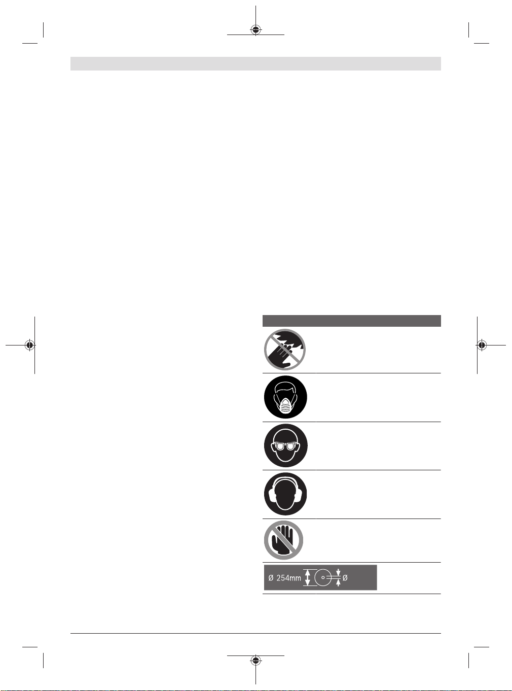
Symbols and their meanings
Keep hands away from the cutting area
while the power tool is running. Con-
tact with the saw blade can lead to injuries.
Wear a dust mask.
Symbols and their meanings
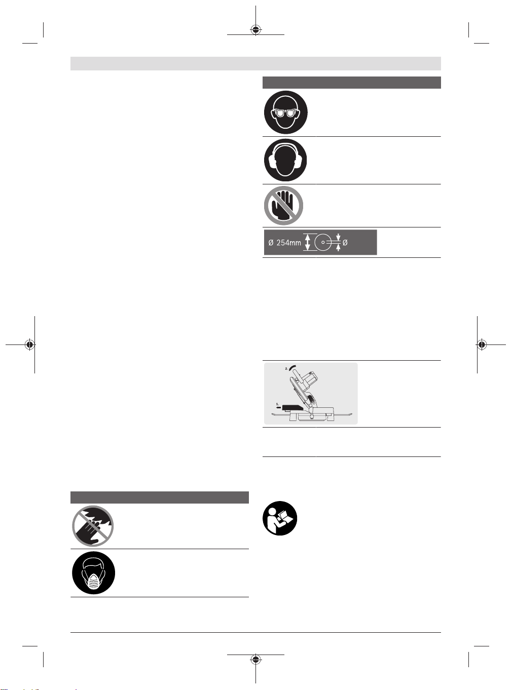
Wear safety goggles.
Wear hearing protection. Exposure to
noise can cause hearing loss.
Danger area! Keep hands, fingers and
arms away from this area.
Take note of the dimensions of the saw
blade. The hole diameter must fit the tool
spindle without play. If it is necessary to
use reducers, ensure that the dimensions
of the reducer are suitable for the base
blade thickness and the saw blade hole
diameter, as well as the tool spindle diameter. Wherever possible, use the reducers provided with the saw blade.
The saw blade diameter must match the
information specified on the symbol.
When sawing bevel angles, the adjustable
fences must be pulled outwards or removed completely.
Product Description and Specifications
Read all the safety and general instructions.
Failure to observe the safety and general instructions may result in electric shock, fire
and/or serious injury.
Please observe the illustrations at the beginning of this operating manual.
Intended Use
The power tool is intended as a stationary machine for making straight lengthways and crossways cuts. It is possible to
cut mitre angles of –47° to +52° and bevel angles of 0° to
45°.
1 609 92A 4YM | (15.05.2019) Bosch Power Tools
English | 13
The power tool is designed with sufficient capacity for sawing hardwood, softwood, chipboard and fibreboard, as well
as aluminium and plastic.
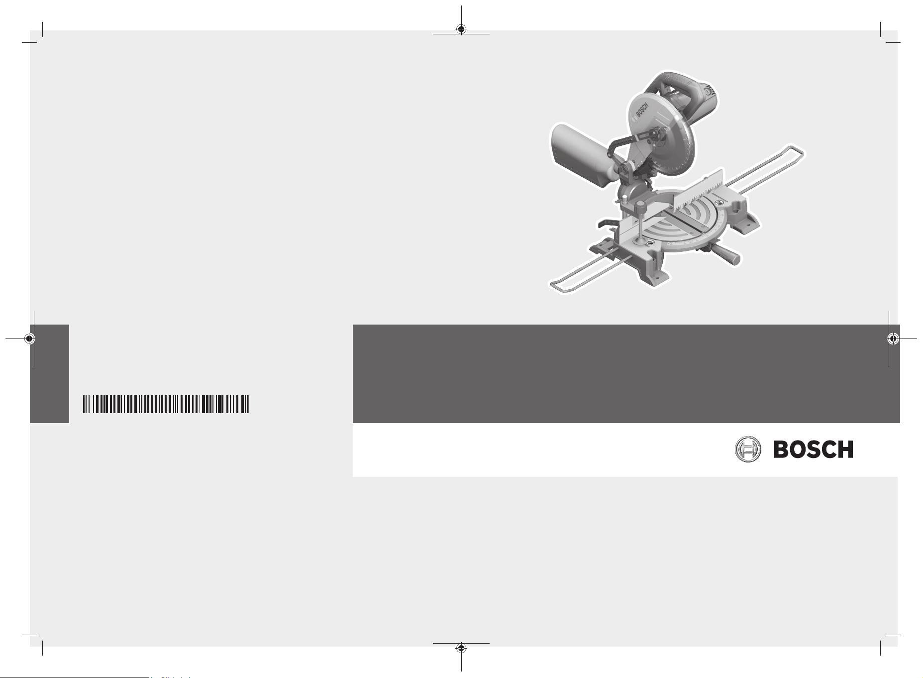
Product Features
The numbering of the product features refers to the diagram
of the power tool on the graphics page.
Protective guard
(1)
Lever for releasing the tool arm
(2)
Handle
(3)
On/off switch
(4)
Retracting blade guard
(5)
Fence
(6)
Saw table
(7)
Holes for screw clamp
(8)
Insert plate
(9)
Locking knob for all mitre angles
(10)
Mitre presetting lever
(11)
Angle indicator for mitre angles
(12)
Scale for mitre angles
(13)
Mounting holes
(14)
Recessed handles
(15)
Drill holes for extension bars
(16)
Adjustable fence
(17)
Screw clamp
(18)
Dust bag
(19)
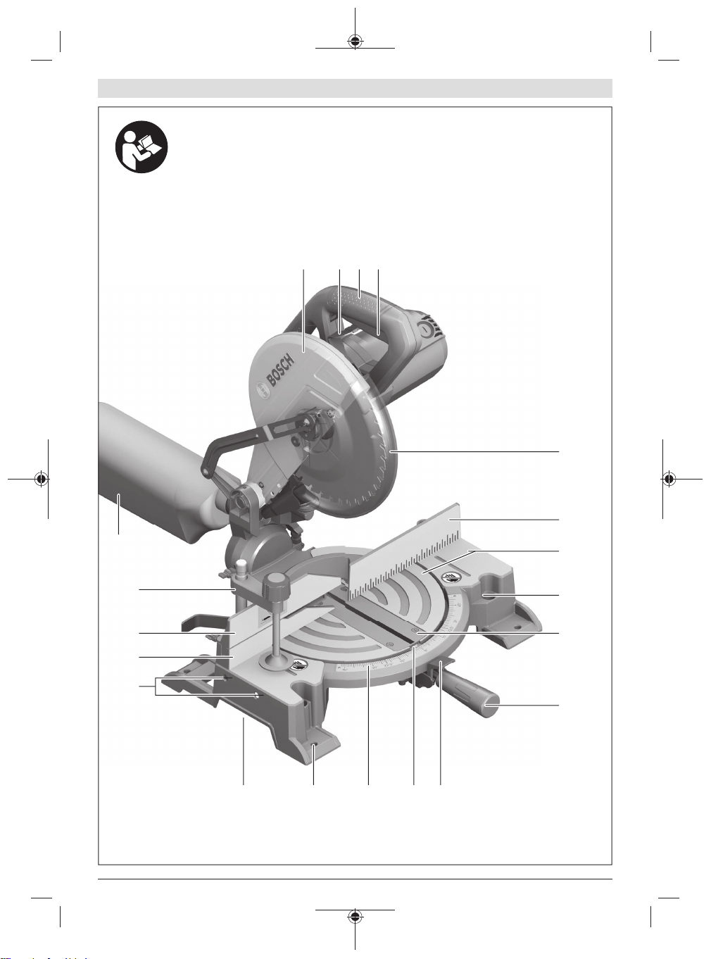
Chip deflector
(20)
Wing bolt for fixing the adjustable fence
(21)
Hex key (6 mm)/cross-headed screwdriver
(22)
Stop screw for 45° bevel angle
(23)
Tilt protector
(24)
Chip ejector
(25)
Clamping handle for all bevel angles
(26)
Transport safety lock
(27)
Transport handle
(28)
Spindle lock
(29)
Depth stop adjusting screw
(30)
Angle indicator for bevel angles
(31)
Scale for bevel angles
(32)
Stop screw for 0° bevel angle
(33)
Holes for tilt protector
(34)
"Tilt protector" fastening set
(35)
Extension bar
(36)
Fastening screw for extension bar
(37)
Cross-head screw (retracting blade guard attach-
(38)
ment)
Hex socket screw for mounting the saw blade
(39)
Clamping flange
(40)
Saw blade
(41)
Inner clamping flange
(42)
Wing bolt for adjusting the height of the threaded
(43)
rod
Threaded rod
(44)
Detents for standard mitre angles
(45)
Screws for insert plate
(46)
Hex socket screw for fence
(47)
Screw for bevel angle indicator
(48)
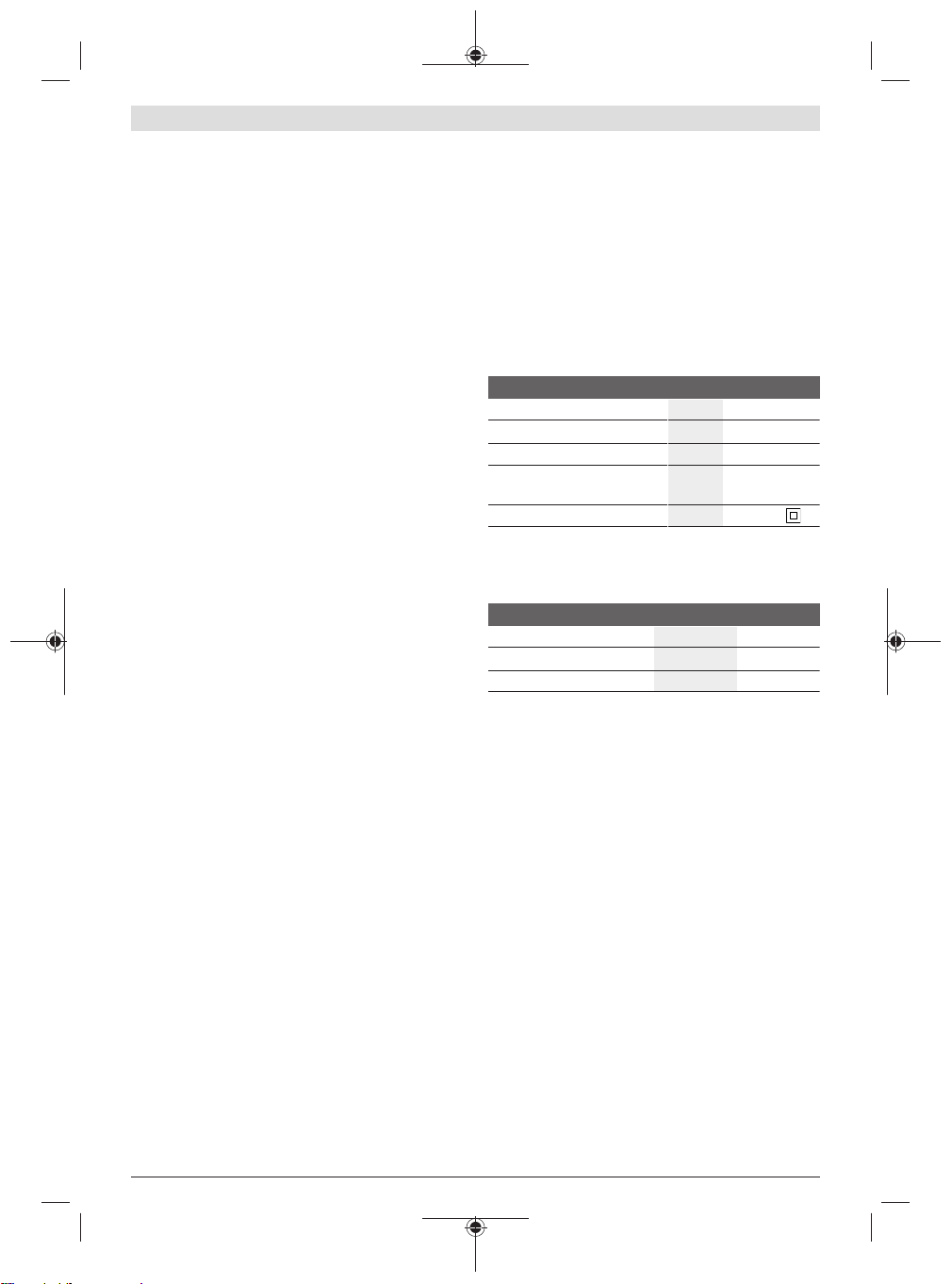
Technical Data
Mitre saw GCM 10 MX
Article number
3 601 M29 0..
Rated power input W 1700
No-load speed min
Weight according to EPTA-Pro-
-1
4800
kg 16.8
cedure 01:2014
Protection class
Permitted workpiece dimensions (maximum/minimum): (see "Permissible workpiece dimensions", page17)
The specifications apply to a rated voltage [U] of 230 V. These specifications may vary at different voltages and in country-specific models.
/ II
Dimensions of suitable saw blades
Saw blade diameter mm 254
Base blade thickness mm 1.8−2.8
Hole diameter mm 25.4
Noise Information
Noise emission values determined according to EN
62841-3-9.
Typically, the A-weighted noise level of the power tool is:
Sound pressure level 92dB(A); sound power level
105dB(A). Uncertainty K = 3dB.
Wear hearing protection
The noise emission value given in these instructions has
been measured in accordance with a standardised measuring procedure and may be used to compare power tools. It
may also be used for a preliminary estimation of noise emissions.
The noise emission value given represents the main applications of the power tool. However, if the power tool is used
for other applications, with different application tools or is
poorly maintained, the noise emission value may differ. This
may significantly increase noise emissions over the total
working period.
To estimate noise emissions accurately, the times when the
tool is switched off, or when it is running but not actually being used, should also be taken into account. This may significantly reduce noise emissions over the total working
period.
Bosch Power Tools 1 609 92A 4YM | (15.05.2019)
14 | English
Assembly
u Avoid starting the power tool unintentionally. The
mains plug must not be connected to the power supply
during assembly or when carrying out any kind of
work on the power tool.
Items included
See the list of items included at the start of
the operating manual.
Check to ensure that all the parts listed below have been
supplied before using the power tool for the first time:
– Mitre saw with mounted saw blade
– Dust bag (19)
– Screw clamp (18)
– Hex key/cross-headed screwdriver(22)
– Tilt protector(24) with fastening set(35) (2 bolts, 2
washers, 2 square nuts)
Note: Check the power tool for possible damage.
Before continuing to use the power tool, carefully check that
all protective devices or slightly damaged parts are working
perfectly and according to specifications. Check that the
moving parts are working perfectly and without jamming;
check whether any parts are damaged. All parts must be fitted correctly and all the conditions necessary to ensure
smooth operation must be met.
If the protective devices or any parts become damaged, you
must have them properly repaired or replaced by an authorised service centre.
Fitting individual components
– Carefully remove all parts included in the delivery from
their packaging.
– Remove all packing material from the power tool and the
accessories provided.
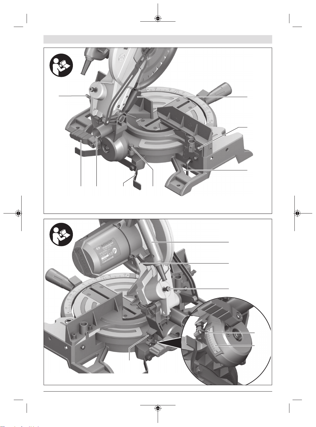
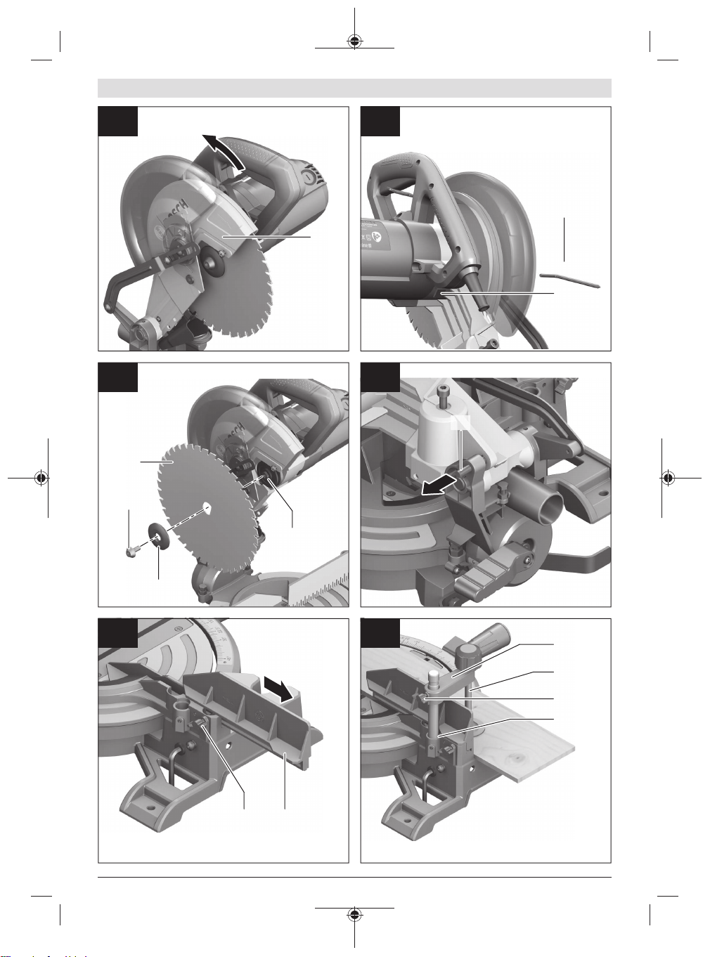
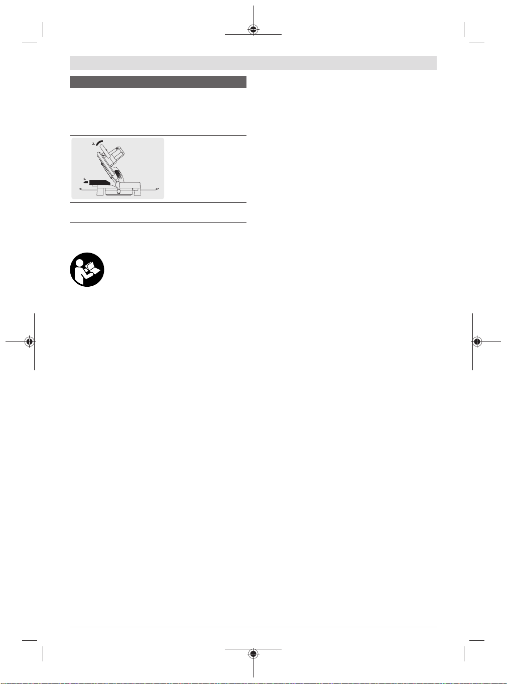
Mounting the tilt protector (see figure A)
Before the power tool is used for the first time, the tilt protector(24) must be installed.
Use the "tilt protector" fastening set(35) for the installation.
– Insert the square nuts(35) into the corresponding
holes(34) in the base plate.
– Place the washers(35) on the fastening screws(35) and
use them to screw the tilt protector(24) into the inserted
nuts.
u Do not remove the tilt protector. Without the tilt pro-
tector, the power tool will not be stable and can tip over
especially when sawing maximum mitre/bevel angles.
Fitting the extension bar (see figure B)
The free end of long and heavy workpieces must have something placed underneath it or be supported.
To extend the saw table further, extension bars can be
mounted both to the left or right of the power tool.
– Push the extension bars(36) on both sides of the power
tool all the way into the corresponding drill holes(16).
– Tighten the fastening screws(37) to secure the extension
bars.
Stationary or flexible mounting
u To ensure safe handling, the power tool must be
mounted on a flat, stable work surface (e.g. work
bench) before use.
Mounting on a work surface (see figure C1−C2)
– Use suitable screw fasteners to secure the power tool to
the work surface. The holes (14) are used for this purpose.
or
– Firmly clamp the base of the power tool to the work sur-
face with commercially available screw clamps.
Mounting on a Bosch saw stand
With the height-adjustable legs, Bosch GTA saw stands
provide firm support for the power tool on any surface. The
workpiece supports of the saw stand are used for underlaying long workpieces.
u Read all the warnings and instructions included with
the saw stand. Failure to observe the warnings and follow instructions may result in electric shock, fire and/or
serious injury.
u Assemble the saw stand properly before mounting the
power tool. Correct assembly is important to prevent the
risk of collapsing.
– Mount the power tool on the saw stand in the transport
position.
Dust/Chip Extraction
The dust from materials such as lead paint, some types of
wood, minerals and metal can be harmful to human health.
Touching or breathing in this dust can trigger allergic reactions and/or cause respiratory illnesses in the user or in
people in the near vicinity.
Certain dusts, such as oak or beech dust, are classified as
carcinogenic, especially in conjunction with wood treatment
additives (chromate, wood preservative). Materials containing asbestos may only be machined by specialists.
– Use a dust extraction system that is suitable for the ma-
terial wherever possible.
– Provide good ventilation at the workplace.
– It is advisable to wear a P2 filter class breathing mask.
The regulations on the material being machined that apply in
the country of use must be observed.
u Avoid dust accumulation at the workplace. Dust can
easily ignite.
The dust/chip extraction system can be blocked by dust,
chips or fragments of the workpiece.
– Switch the power tool off and pull the mains plug out of
the socket.
– Wait until the saw blade has come to a complete stop.
– Determine the cause of the blockage and eliminate it.
1 609 92A 4YM | (15.05.2019) Bosch Power Tools

English | 15
Self-generated dust extraction (see figure D)
For basic chip collection, use the dust bag (19) provided.
– Attach the dust bag (19) to the chip ejector (25).
During sawing, the dust bag must not come into contact with
moving tool components.
Always empty the dust bag in good time.
u Check and clean the dust bag each time after using.
u When sawing aluminium, remove the dust bag to avoid
the risk of fire.
External Dust Extraction
You can also attach a dust extraction hose (35 mm diameter) to the chip ejector (25) for extraction.
– Connect the dust extraction hose to the chip ejector (25).
The dust extractor must be suitable for the material being
worked.
When extracting dry dust that is especially detrimental to
health or carcinogenic, use a special dust extractor.
Changing the saw blade (see figures E1−E3)
u Pull the plug out of the socket before carrying out any
work on the power tool.
u Wear protective gloves when fitting the saw blade.
There is a risk of injury when touching the saw blade.
Only use saw blades that have a maximum permitted speed
higher than the no-load speed of the power tool.
Only use saw blades that match the specifications given in
this operating manual and that have been tested and marked
in accordance with EN847-1.
Only use saw blades that are recommended by the power
tool manufacturer and are suitable for use on the material
you want to saw. This will prevent the saw teeth overheating
when sawing.
Removing the saw blade
– Bring the power tool into the work position.
– Push the lever (2) and swing the retracting blade guard
(5) back as far as it will go.
Hold the retracting blade guard in this position.
– Loosen the screw (38) with the cross-headed screw-
driver (22) provided until the retracting blade guard attachment can also be swivelled all the way back.
– Turn the hex socket screw (39) using the hex key (22)
provided while pressing the spindle lock (29) until it engages.
– Press and hold the spindle lock (29) and loosen the
screw (39) by turning it clockwise (left-hand thread).
– Remove the clamping flange (40).
– Remove the saw blade (41).
Fitting the saw blade
If required, clean all the parts you want to fit before installing
them.
– Place the new saw blade on the inner clamping flange
(42).
u When fitting the saw blade, make sure that the cutting
direction of the teeth (arrow direction on the saw
blade) matches the direction of the arrow on the protective guard.
– Place on the clamping flange (40) and the screw (39).
Press the spindle lock (29) until it engages and tighten
the screw by turning it anticlockwise.
– Push the retracting blade guard(5) forwards and down
until the screw(38) engages in the corresponding recess.
To do so, you may need to hold the tool arm against the
handle in order to generate sufficient pre-tension on the
retracting blade guard.
– Fasten the retracting blade guard (5) again (tighten
screw(38)).
– Push the lever (2) and guide the retracting blade guard
down again.
u When attaching the clamping flange, ensure that the
wide side faces the saw blade. The saw blade cannot be
tightened if it is installed the other way round.
Operation
u Pull the plug out of the socket before carrying out any
work on the power tool.
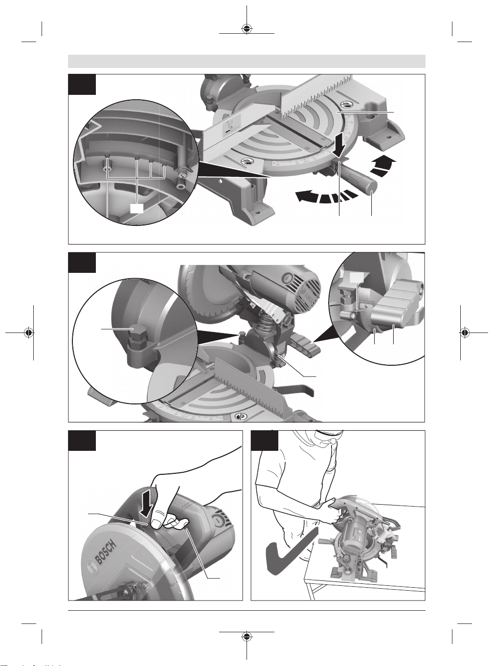
Transport safety lock (see figure F)
The transport safety lock (27) makes it easier to handle the
power tool when transporting it to various working locations.
Unlocking the power tool (work position)
– Press the tool arm down slightly by the handle (3) to re-
lease the transport safety lock (27).
– Pull the transport safety lock (27) all the way out.
– Slowly guide the tool arm upwards.
Note: Make sure that the transport safety lock is not pushed
in when working, otherwise the tool arm will not be able to
be swivelled to the required depth.
Locking the power tool (transport position)
– Swivel the depth stop inwards so that the tool arm can be
swivelled all the way downwards by the handle (3).
– Push the lever (2) while swivelling the tool arm down-
wards by the handle (3) until you can press the transport
safety lock (27) all the way in.
The tool arm is now securely locked and ready for transportation.
Preparing for operation
Moving the fence (see figure G)
You have to move the adjustable fence (17) to saw bevel
angles.
– Loosen the wing bolt (21).
– Pull the adjustable fence (17) all the way out.
– Retighten the wing bolt (21).
Bosch Power Tools 1 609 92A 4YM | (15.05.2019)

16 | English
After sawing the bevel angles, slide the adjustable fence
(17) back again (loosen the wing bolt (21); slide the fence
(17) all the way in; retighten the wing bolt).
Clamping the workpiece (see figure H)
To ensure maximum safety while working, the workpiece
must always be firmly clamped.
Do not saw workpieces that are too small to clamp firmly.
– Press the workpiece firmly against the fences (6) and
(17).
– Insert the supplied screw clamp (18) into one of the cor-
responding holes (8).
– Loosen the wing bolt (43) and adjust the screw clamp to
the workpiece. Tighten the wing bolt again.
– Tighten the threaded rod (44) to fix the workpiece in
place.
Releasing the workpiece
– To loosen the screw clamp, turn the threaded rod (44)
anticlockwise.
Setting mitre and bevel angles
u Pull the plug out of the socket before carrying out any
work on the power tool.
To ensure precise cuts, the basic settings of the power tool
must be checked and adjusted as necessary after intensive
use.
Experience and suitable special tools are required for this.
A Bosch after-sales service point will handle this work
quickly and reliably.
u Always tighten the locking knob (10) firmly before
sawing. Otherwise the saw blade can become wedged in
the workpiece.
Setting mitre angles (see figure I)
The mitre angle can be set between 47° (left side) and 52°
(right side).
– Loosen the locking knob (10) if it is tightened.
– Push the lever (11), turn the saw table (7) left or right by
the locking knob and set the required mitre angle using
the angle indicator (12).
– Retighten the locking knob (10).
For quick and precise setting of commonly used mitre
angles, detents (45) are provided on the saw table:
Left Right
0°
45°; 30°; 22.5°; 15° 15°; 22.5°; 30°; 45°
– Loosen the locking knob (10) if it is tightened.
– Push the lever (11) and turn the saw table (7) left or right
to the required detent.
– Release the lever again. The lever must be felt to engage
in the detent.
– Retighten the locking knob (10).
Setting bevel angles (see figure J)
The bevel angle can be set between 0° and 45°.
– Loosen the clamping handle (26).
– Use the handle (3) to swivel the tool arm until the angle
indicator (31) shows the required bevel angle.
– Hold the tool arm in this position and retighten the clamp-
ing handle (26).
To set the standard angles of 0° and 45° quickly and accurately, stop screws are provided ex-works ((33) and
(23)).
– Loosen the clamping handle (26).
– Swivel the tool arm by the handle (3) all the way to the
right (0°) or all the way to the left (45°).
– Retighten the clamping handle (26).
Start-up
u Pay attention to the mains voltage. The voltage of the
power source must match the voltage specified on the
rating plate of the power tool. Power tools marked
with 230V can also be operated with 220V.
u Products that are only sold in AUS and NZ: Use a resid-
ual current device (RCD) with a nominal residual current
of 30 mA or less.
Switching on (see figure K)
– To start the tool, press the on/off switch (4) and keep it
pressed.
Note: For safety reasons, the on/off switch (4) cannot be
locked; it must remain pressed during the entire operation.
The tool arm can only be guided downwards by pushing the
lever (2).
– For sawing, the lever (2) must therefore be pushed while
the on/off switch (4) is pressed.
Switching off – To switch off, release the on/off switch (4).
Practical advice
General sawing instructions
u Always tighten the locking knob (10) and the clamp-
ing handle (26) firmly before sawing. Otherwise the
saw blade can become wedged in the workpiece.
u For all cuts, it must first be ensured that the saw blade
at no time can come in contact with the fence, screw
clamps or other machine parts. Remove any mounted
auxiliary stops or adjust them accordingly.
Protect the saw blade against impact and shock. Do not subject the saw blade to lateral pressure.
Do not saw warped/bent workpieces. The workpiece must
always have a straight edge to face against the fence.
The free end of long and heavy workpieces must have something placed underneath it or be supported.
Make sure that the retracting blade guard operates properly
and that it can move freely. The retracting blade guard must
open when the tool arm is guided downward. When the tool
arm is guided upward, the retracting blade guard must close
again over the saw blade and lock in the uppermost position
of the tool arm.
1 609 92A 4YM | (15.05.2019) Bosch Power Tools
English | 17
Only saw materials which are permitted within the scope of
the intended use.
Position of the operator (see figure L)
u Do not stand in line with the saw blade in front of the
power tool. Always stand to the side of the saw blade.
This protects your body against possible kickback.
– Keep hands, fingers and arms away from the rotating saw
blade.
– Do not reach one hand across the other when in front of
the tool arm.
Permissible workpiece dimensions
Maximum workpiece dimensions:
Mitre
angle
Bevel
angle
Height x width [mm]
at max. height at max. width
0° 0° 89 x 89 62 x 130
45° 0° 86 x 67 65 x 91
0° 45° 44 x 95 32 x 130
45° 45° 44 x 67 32 x 91
Minimum workpiece dimensions (= all workpieces that can
be secured left or right of the saw blade using the supplied
quick-action clamp ): 110 x 130mm (length x width)
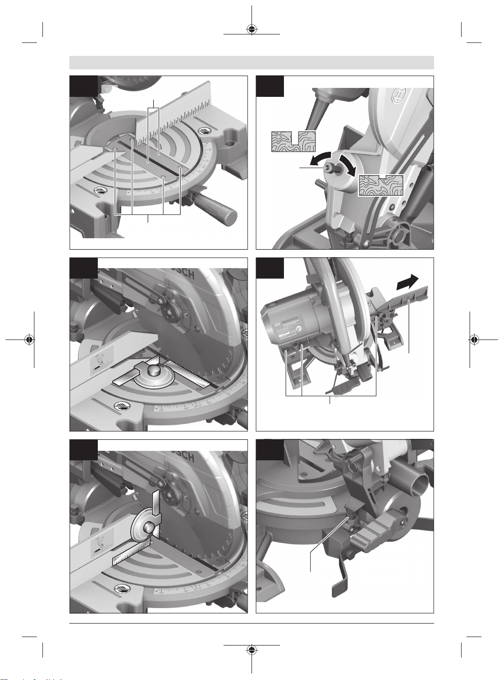
Max. cutting depth (0°/0°): 89mm Replacing insert plates (see figure M)
The insert plate (9) can become worn after long use of the
power tool.
Replace faulty insert plates.
– Bring the power tool into the work position.
– Unscrew the screws (46) using the cross-headed screw-
driver (22) provided and remove the old insert plate.
– Screw the insert plate as far as possible to the right with
the screws(46) so that the saw blade does not come into
contact with the insert plate over the entire length of the
possible cutting motion.
Sawing (cutting)
– Firmly clamp the workpiece as appropriate for its dimen-
sions.
– Set the required mitre and/or bevel angle.
– Set the height of the adjusting screw (30) so that the
workpiece can be sawn through completely.
– Switch the power tool on.
– Push the lever (2) and slowly guide the tool arm down-
wards using the handle (3).
– Saw through the workpiece applying uniform feed.
– Switch off the power tool and wait until the saw blade has
come to a complete stop.
– Slowly guide the tool arm upwards.
Adjusting the depth stop (sawing the groove) (see figure N)
The adjusting screw (30) of the depth stop has to be turned
clockwise if you want to saw a groove.
– Swivel the tool arm by the handle (3) into the position at
which the required groove depth is reached.
– Turn the adjusting screw (30) clockwise until the end of
the screw touches the housing stop.
– Slowly guide the tool arm upwards.
Special workpieces
When sawing curved or round workpieces, these must be especially secured against slipping. At the cutting line, there
should be no gap between the workpiece, fence and saw
table.
If necessary, you will need to manufacture special fixtures.
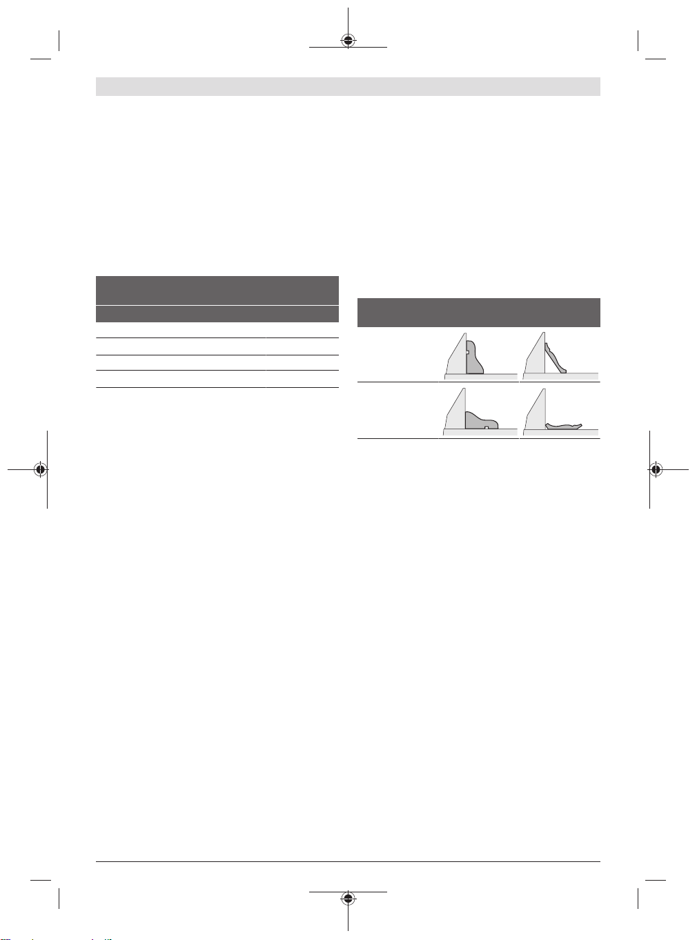
Working on mouldings
Mouldings can be sawn in two different ways:
Positioning of
Base moulding Crown moulding
workpiece
– Placed against
the fence
– Lying flat on the
saw table
Always check the set mitre and/or bevel angle first by making trial cuts in scrap wood.
Checking and Adjusting the Basic Settings
To ensure precise cuts, the basic settings of the power tool
must be checked and adjusted as necessary after intensive
use.
Experience and suitable special tools are required for this.
A Bosch after-sales service point will handle this work
quickly and reliably.
Aligning the fence
– Bring the power tool into the transport position.
– Turn the saw table (7) to the 0° detent(45). The lever
(11) must be felt to engage in the detent.
– Pull the adjustable fence (17) all the way out.
Checking (see figure O1)
– Set an angle gauge to 90° and position it flush with the
saw blade (41) between the fence (6) and the saw blade
on the saw table(7).
The leg of the angle gauge must be flush with the fence over
the complete length.
Setting (see figure O2)
– Loosen all hex socket screws (47) with the hex key (22)
provided.
– Rotate the fence (6) until the angle gauge is flush over the
complete length.
– Re-tighten the screws.
Setting the Standard 0° Bevel Angle
– Bring the power tool into the transport position.
Bosch Power Tools 1 609 92A 4YM | (15.05.2019)
18 | English
– Turn the saw table (7) to the 0° detent (45). The lever
(11) must be felt to engage in the detent. Checking (see figure P1)
– Set an angle gauge to 90° and place it on the saw table
(7).
The leg of the angle gauge must be flush with the saw blade
(41) along its entire length. Setting (see figure P2)
– Loosen the clamping handle (26).
– Loosen the lock nut of the stop screw (33) using a com-
mercially available ring spanner or open-ended spanner
(13mm).
– Turn the stop screw as far in or out as needed until the leg
of the angle gauge is flush with the saw blade along its en-
tire length.
– Retighten the clamping handle (26).
– Then retighten the lock nut of the stop screw (33).
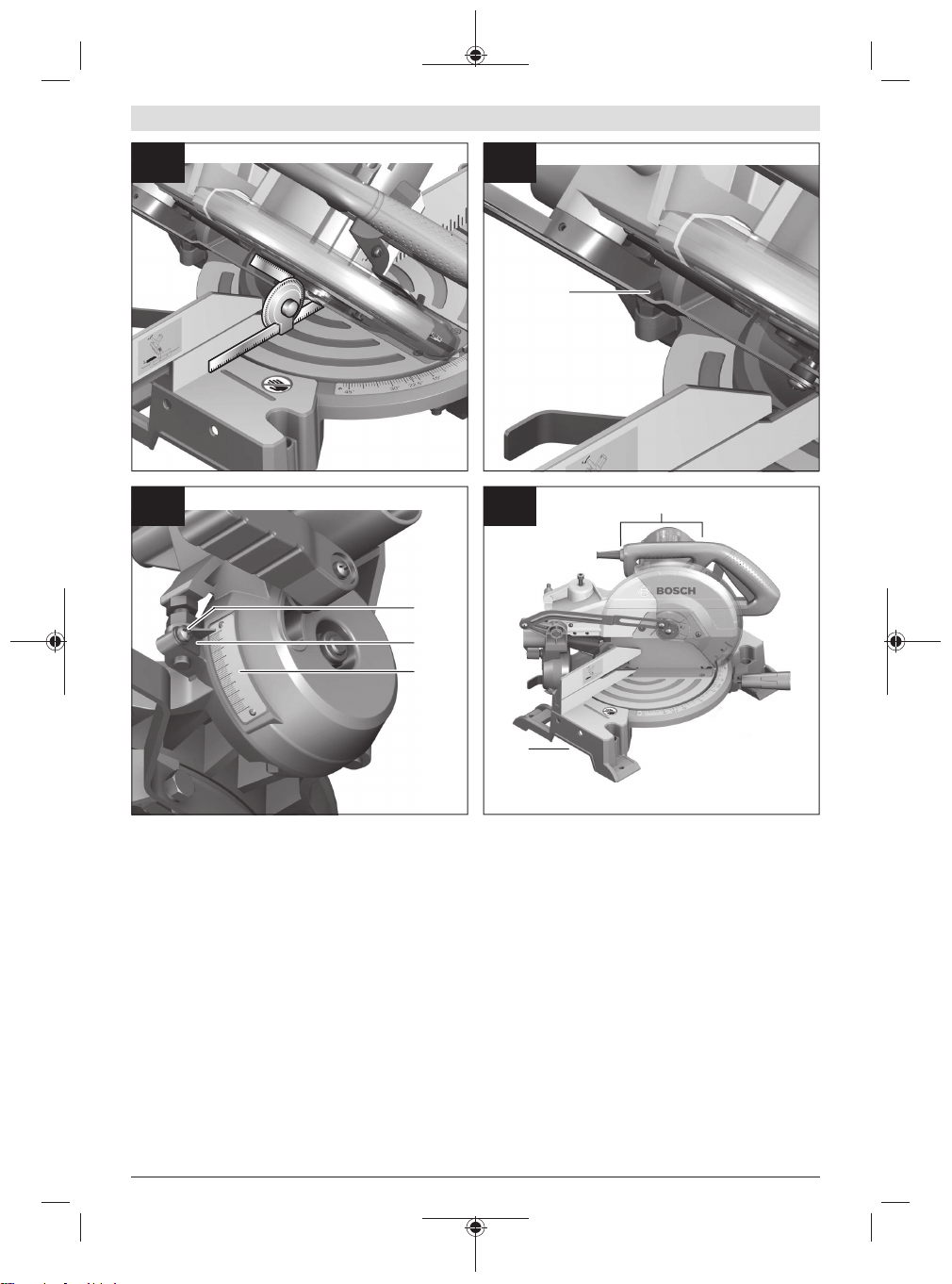
If the angle indicator (31) is not aligned with the 0° mark on
the scale (32) following adjustment, loosen the screw (48)
using a commercially available cross-headed screwdriver
and align the angle indicator along the 0° mark. (See figure
R)
Setting the standard 45° bevel angle
– Bring the power tool into the work position.
– Turn the saw table (7) to the 0° detent (45). The lever
(11) must be felt to engage in the detent.
– Loosen the clamping handle (26) and use the handle (3)
to swivel the tool arm all the way to the left (45°).
Checking (see figure Q1)
– Set an angle gauge to 45° and place it on the saw table
(7).
The leg of the angle gauge must be flush with the saw blade
(41) along its entire length. Setting (see figure Q2)
– Loosen the lock nut of the stop screw (23) using a com-
mercially available ring spanner or open-ended spanner
(13mm).
– Turn the stop screw as far in or out as needed until the leg
of the angle gauge is flush with the saw blade along its en-
tire length.
– Retighten the clamping handle (26).
– Then retighten the lock nut of the stop screw (23).
If the angle indicator (31) is not aligned with the 45° mark on
the scale (32) following adjustment, first check the 0° setting for the bevel angle and the angle indicator once more.
Then repeat the adjustment of the 45° bevel angle.
Transport (see figure S)
Before transporting the power tool, the following steps must
be carried out:
– Bring the power tool into the transport position.
– Remove all accessories that cannot be securely fitted to
the power tool.
If possible, transport unused saw blades in a closed con-
tainer.
– Carry the power tool by the transport handle (28) or hold
it by the recessed handles(15) on the sides of the saw
table.
u Only use the transport devices to transport the power
tool and never the protective devices.
Maintenance and servicing
Maintenance and cleaning
u Pull the plug out of the socket before carrying out any
work on the power tool.
u To ensure safe and efficient operation, always keep
the power tool and the ventilation slots clean.
In order to avoid safety hazards, if the power supply cord
needs to be replaced, this must be done by Bosch or by an
after-sales service centre that is authorised to repair Bosch
power tools.
The retracting blade guard must always be able to move
freely and retract automatically. It is therefore important to
keep the area around the retracting blade guard clean at all
times.
Always remove dust and chips after working by blowing out
with compressed air or using a brush.
Accessories
Article number
3601M29040, 3601M290B0:
Extension bar
Saw blades for hardwood, composites, plastic and nonferrous metals
254 x 25.4 mm saw blade, 100 teeth 1 609 B00 844
Saw blades for wood and fibreboard, panels and strips
254 x 25.4 mm saw blade, 40 teeth 2 608 673 047
254 x 25.4 mm saw blade, 100 teeth 2 608 640 904
After-Sales Service and Application Service
Our after-sales service responds to your questions concerning maintenance and repair of your product as well as spare
parts. You can find explosion drawings and information on
spare parts at: www.bosch-pt.com
The Bosch product use advice team will be happy to help you
with any questions about our products and their accessories.
In all correspondence and spare parts orders, please always
include the 10‑digit article number given on the nameplate
of the product.
Cambodia
Robert Bosch (Cambodia) Co., Ltd
Unit 8BC, GT Tower, 08th Floor, Street 169,
Czechoslovakia Blvd, Sangkat Veal Vong
Khan 7 Makara, Phnom Penh
VAT TIN: 100 169 511
Tel.: +855 23 900 685
1 619 PA6 916
1 609 92A 4YM | (15.05.2019) Bosch Power Tools

English | 19
Tel.: +855 23 900 660
www.bosch.com.kh
People’s Republic of China
China Mainland
Bosch Power Tool (China) Co. Ltd.
Bosch Service Center
567, Bin Kang Road
Bin Kang District
Hangzhou, Zhejiang Province
China 310052
Tel.: (0571) 8887 5566 / 5588
Fax: (0571) 8887 6688 x 5566# / 5588#
E-mail: bsc.hz@cn.bosch.com
www.bosch-pt.com.cn
HK and Macau Special Administrative Regions
Robert Bosch Co. Ltd.
21st Floor, 625 King’s Road
North Point, Hong Kong
Customer Service Hotline: +852 2101 0235
Fax: +852 2590 9762
E-mail: info@hk.bosch.com
www.bosch-pt.com.hk
India
Bosch Service Center
69, Habibullah Road, (next to PSBB School), T. Nagar
Chennai–600077
Phone: (044) 64561816
Bosch Service Center Rishyamook
85A, Panchkuin Road
New Delhi–110001
Phone: (011) 43166190
Bosch Service Center 79,
Crystal Bldg., Dr. Annie Besant Road, Worli
Mumbai–400018
Phone: (022) 39569936 / (022 )39569959 /
(022) 39569967 / (022) 24952071
Indonesia
PT Robert Bosch
Palma Tower 10th Floor
Jalan RA Kartini II-S Kaveling 6
Pondok Pinang, Kebayoran Lama
Jakarta Selatan 12310
Tel.: (21) 3005-5800
www.bosch-pt.co.id
Malaysia
Robert Bosch Sdn. Bhd.(220975-V) PT/SMY
No. 8A, Jalan 13/6
46200 Petaling Jaya
Selangor
Tel.: (03) 79663194
Toll-Free: 1800 880188
Fax: (03) 79583838
E-mail: kiathoe.chong@my.bosch.com
www.bosch-pt.com.my
Pakistan
Robert Bosch Middle East FZE – Pakistan Liaison Office
2nd Floor Plaza # 10, CCA Block, DHA Phase 5
Lahore, 54810
Phone: +92(303)4444311
E-mail: Faisal.Khan@bosch.com
Philippines
Robert Bosch, Inc.
28th Floor Fort Legend Towers,
3rd Avenue corner 31st Street,
Fort Bonifacio, Global City,
1634 Taguig City
Tel.: (632) 8703871
Fax: (632) 8703870
www.bosch-pt.com.ph
Singapore
Powerwell Service Centre Ptd Ltd
Bosch Authorised Service Centre (Power Tools)
4012 Ang Mo Kio Ave 10, #01-02 TECHplace
Singapore 569628
Tel.: 6452 1770
Fax: 6452 1760
E-mail: ask@powerwellsc.com
www.powerwellsc.com
www.bosch-pt.com.sg
Thailand
Robert Bosch Ltd.
Liberty Square Building
No. 287, 11 Floor
Silom Road, Bangrak
Bangkok 10500
Tel.: 02 6393111
Fax: 02 2384783
Robert Bosch Ltd., P. O. Box 2054
Bangkok 10501
www.bosch.co.th
Bosch Service – Training Centre
La Salle Tower Ground Floor Unit No.2
10/11 La Salle Moo 16
Srinakharin Road
Bangkaew, Bang Plee
Samutprakarn 10540
Tel.: 02 7587555
Fax: 02 7587525
Vietnam
Branch of Bosch Vietnam Co., Ltd in HCMC
14th floor, Deutsches Haus, 33 Le Duan
Ben Nghe Ward, District 1, Ho Chi Minh City
Tel.: (028) 6258 3690
Fax: (028) 6258 3692 - 6258 3694
Hotline: (028) 6250 8555
E-mail: tuvankhachhang-pt@vn.bosch.com
www.bosch-pt.com.vn
Armenia, Azerbaijan, Georgia, Kyrgyzstan, Mongolia,
Tajikistan, Turkmenistan, Uzbekistan
TOO "Robert Bosch" Power Tools, After Sales Service
Rayimbek Ave., 169/1
050050, Almaty, Kazakhstan
Service e-mail: service.pt.ka@bosch.com
Official website: www.bosch.com, www.bosch-pt.com
Bosch Power Tools 1 609 92A 4YM | (15.05.2019)

20 | English
Bahrain
Hatem Al Juffali Technical Equipment Establishment.
Kingdom of Bahrain, Setra Highway, Al Aker Area
Phone: +966126971777-311
Fax: +97317704257
E-mail: h.berjas@eajb.com.sa
Egypt
RBEG-LLC
22 Kamal Eldin Hussein
Sheraton Heliopolis
11799 Cairo
E-mail: boschegypt.powertools@eg.bosch.com
Iran
Robert Bosch Iran
3rd Floor, No 3, Maadiran Building
Aftab St., Khodami St., Vanak Sq.
Tehran 1994834571
Phone: +9821 86092057
Iraq
Sahba Technology Group
Al Muthana airport road
Baghdad
Phone: +9647901906953
Phone Dubai: +97143973851
E-mail: bosch@sahbatechnology.com
Jordan
Roots Arabia – Jordan
Nasser Bin Jameel street, Building 37 Al Rabiah
11194 Amman
Phone: +962 6 5545778
E-mail: bosch@rootsjordan.com
Kuwait
Al Qurain Automotive Trading Company
Shuwaikh Industrial Area, Block 1, Plot 16, Street 3rd
P.O. Box 164 – Safat 13002
Phone: 24810844
Fax: 24810879
E-mail: josephkr@aaalmutawa.com
Lebanon
Tehini Hana & Co. S.A.R.L.
P.O. Box 90-449
Jdeideh
Dora-Beirut
Phone: +9611255211
E-mail: service-pt@tehini-hana.com
Libya
El Naser for Workshop Tools
Swanee Road, Alfalah Area
Tripoli
Phone: +218 21 4811184
Oman
Malatan Trading & Contracting LLC
P.O. Box 131
Ruwi, 112 Sultanate of Oman
Phone: +968 99886794
E-mail: malatanpowertools@malatan.net
Qatar
International Construction Solutions W L L
P. O. Box 51,
Doha Phone: +974 40065458
Fax: +974 4453 8585
E-mail: csd@icsdoha.com
Saudi Arabia
Juffali Technical Equipment Co. (JTECO)
Kilo 14, Madinah Road, Al Bawadi District
Jeddah 21431
Phone: +966 2 6672222 Ext. 1528
Fax: +966 2 6676308
E-mail: roland@eajb.com.sa
Syria
Dallal Establishment for Power Tools
P.O. Box 1030
Aleppo
Phone: +963212116083
E-mail: rita.dallal@hotmail.com
United Arab Emirates
Central Motors & Equipment LLC, P.O. Box 1984
Al-Wahda Street – Old Sana Building
Sharjah
Phone: +971 6 593 2777
Fax: +971 6 533 2269
E-mail: powertools@centralmotors.ae
Yemen
Abualrejal Trading Corporation
Sana’a Zubiery St. Front to new Parliament Building
Phone: +967-1-202010
Fax: +967-1-279029
E-mail: tech-tools@abualrejal.com
Ethiopia
Forever plc
Kebele 2,754, BP 4806,
Addis Ababa
Phone: +251 111 560 600
E-mail: foreverplc@ethionet.et
Ghana
Peew-Williams Services Company Ltd
Mile 7, Plot 331, Before Achimota Mall.
Accra
Tel. +233552352511
E-mail: info@peew-williams.com
Kenya
Robert Bosch East Africa Ltd
Mpaka Road P.O. Box 856
00606 Nairobi
Nigeria
Robert Bosch Nigeria Ltd.
52–54 Isaac John Street P.O. Box
GRA Ikeja – Lagos
Republic of South Africa
Customer service
Hotline: (011) 6519600
1 609 92A 4YM | (15.05.2019) Bosch Power Tools
Gauteng – BSC Service Centre
35 Roper Street, New Centre
Johannesburg
Tel.: (011) 4939375
Fax: (011) 4930126
E-mail: bsctools@icon.co.za
KZN – BSC Service Centre
Unit E, Almar Centre
143 Crompton Street
Pinetown
Tel.: (031) 7012120
Fax: (031) 7012446
E-mail: bsc.dur@za.bosch.com
Western Cape – BSC Service Centre
Democracy Way, Prosperity Park
Milnerton
Tel.: (021) 5512577
Fax: (021) 5513223
E-mail: bsc@zsd.co.za
Bosch Headquarters
Midrand, Gauteng
Tel.: (011) 6519600
Fax: (011) 6519880
E-mail: rbsa-hq.pts@za.bosch.com
Tanzania
Diesel & Autoelectric Service Ltd.
117 Nyerere Rd., P.O. Box 70839
Vingunguti 12109, Dar Es Salaam
Phone: +255 222 861 793/794
Australia, New Zealand and Pacific Islands
Robert Bosch Australia Pty. Ltd.
Power Tools
Locked Bag 66
Clayton South VIC 3169
Customer Contact Center
Inside Australia:
Phone: (01300) 307044
Fax: (01300) 307045
Inside New Zealand:
Phone: (0800) 543353
Fax: (0800) 428570
Outside AU and NZ:
Phone: +61 3 95415555
www.bosch-pt.com.au
www.bosch-pt.co.nz
Disposal
The power tool, accessories and packaging should be recycled in an environmentally friendly manner.
Do not dispose of power tools along with
household waste.
中文 | 21
中文
安全规章
电动工具通用安全警告
警告!
明!
不遵照以下警 告和说明会导致电击、着火和/
或严重伤 害。
保存所有警告和说明书以备查阅。
在所有下列的警告中术语" 电动工具" 指市电驱动
(有线)电动工具或电池驱动(无线)电动工具。
工作场地的安全
保持工作场地清洁和明亮。
u
引 发事故。
不要在易爆环境,如有易燃液体、气体或粉尘的
u
环 境下操作电动工具。
燃粉 尘或气体。
让儿童和旁观者离开后操作电动工具。
u
集 中会使操作者失去对工具的控制。
电气安全
电动工具插头必须与插座相配。绝不能以任何方
u
式 改装插头。需接地的电动工具不能使用任何转
换插 头。
击危 险。
避免人体接触接地表面,如管道、散热片和冰
u
箱。
如果你身体接地会增加电击危险。
不得将电动工具暴露在雨中或潮湿环境中。
u
入 电动工具将增加电击危险。
不得滥用电线。绝不能用电线搬运、拉动电动工
u
具 或拔出其插头。使电线远离热源、油、锐边或
运动 部件。
当在户外使用电动工具时,使用适合户外使用的
u
外 接软线。
险。
如果在潮湿环境下操作电动工具是不可避免的,
u
应 使用剩余电流动作保护器(RCD)。
RCD 可减 小电击危险。
人身安全
保持警觉,当操作电动工具时关注所从事的操作
u
并 保持清醒。当你感到疲倦,或在有药物、酒精
或治 疗反应时,不要操作电动工具。
工具时 瞬间的疏忽会导致严重人身伤害。
警告! 阅读所有警告和所有说
混乱和黑暗的场地会
电动工具产生的火花会点
注意力不
未经改装的插头和相配的插座将减少电
水进
受损或缠绕的软线会增加电击危险。
适合户外使用的软线将减少电击危
使用
在操作电动
Bosch Power Tools 1 609 92A 4YM | (15.05.2019)

22 | 中文
使用个人防护装置。始终佩戴护目镜。
u
安全装
置, 诸如适当条件下使用防尘面具、防滑安全
鞋、安全 帽、听力防护等装置能减少人身伤害。
防止意外起动。确保开关在连接电源和/ 或电池
u
盒、拿起或搬运工具时处于关断位置。
手指放在
已 接通电源的开关上或开关处于接通时插入插头
可能 会导致危险。
在电动工具接通之前,拿掉所有调节钥匙或扳
u
手。
遗留在电动工具旋转零件上的扳手或钥匙会
导致人 身伤害。
手不要伸展得太长。时刻注意立足点和身体平
u
衡。
这样在意外情况下能很好地控制电动工具。
着装适当。不要穿宽松衣服或佩戴饰品。让衣
u
服、 手套和头发远离运动部件。
宽松衣服、佩饰
或长发 可能会卷入运动部件中。
如果提供了与排屑、集尘设备连接用的装置,要
u
确 保他们连接完好且使用得当。
使用这些装置可
减少 尘屑引起的危险。
即使由于经常使用电动工具而对此非常熟悉,也
u
不要就认为可以高枕无忧而忽略工具的安全规
定。
粗心大意的行为可能在瞬间就造成严重的伤
害。
电动工具使用和注意事项电动工具使用和注意事项
不要滥用电动工具,根据用途使用适当的电动工
u
具。
选用适当设计的电动工具会使你工作更有
效、 更安全。
如果开关不能接通或关断工具电源,则不能使用
u
该 电动工具。
如果开关不能接通或关断工具电
源,则不能使用该 电动工具。
在进行任何调节、更换附件或贮存电动工具之
u
前, 必须从电源上拔掉插头和/ 或使电池盒与工
具脱 开。
这种防护性措施将减少工具意外起动的
危险。
将闲置不用的电动工具贮存在儿童所及范围之
u
外, 并且不要让不熟悉电动工具或对这些说明不
了解的 人操作电动工具。
电动工具在未经培训的
用户手中 是危险的。
保养电动工具。检查运动件是否调整到位或卡
u
住, 检查零件破损情况和影响电动工具运行的其
他状 况。如有损坏,电动工具应在使用前修理
好。
许多 事故由维护不良的电动工具引发。
保持切削刀具锋利和清洁。
u
保养良好的有锋利切
削 刃的刀具不易卡住而且容易控制。
按照使用说明书,考虑作业条件和进行的作业来
u
使 用电动工具、附件和工具的刀头等。
将电动工
具用 于那些与其用途不符的操作可能会导致危
险。
保持手柄和握持表面干燥、清洁、无油污。
u
发情况下,滑溜的手柄和握持表面无法确保安全
地握持和控制工具。
维修
将电动工具用 于那些与其用途不符的操作可能会
u
导致危险。
. 这样将确保所维修的电动工具的安全
性。
斜切锯安全警告
斜切锯用于切割木材及类似木材的产品,不得与
u
切割砂轮一起使用而用于切割铁质材料(比如
棒、杆、螺柱等)。
部防护罩)卡住。砂轮切割产生的火花会烧坏下
部防护罩、切口嵌件和其它塑料零部件。
尽可能使用夹箍来支承加工件。如果用手支承加
u
工件,必须始终确保手与锯片的每一侧至少相距
100 mm。如果加工件太小而不能稳固夹紧或用手
握住,则不要使用此锯切割。
过近,因接触锯片而导致受伤的风险就会增大。
加工件必须保持固定和夹紧,或紧靠栅栏和桌
u
面。不要将加工件送入锯片或以任何方式徒手切
割。
未固定或可移动的加工件可能会高速抛出,
从而导致受伤。
采用推入方式切割加工件。不要采用拉动方式。
u
进行切割时,抬起锯头并将其拉出至加工件上方
而不要进行切割,起动电机,将锯头向下压,并
将锯推入加工件。
会导致锯片攀爬到加工件顶部,并将锯片总成猛
烈抛向操作员。
切勿将手交叉放在锯片前面或后面的目标切割线
u
上。
交叉用手支承加工件(即用左手将加工件固
定在锯片右侧,或用右手将加工件固定在锯片左
侧)非常危险。
当锯片旋转时,不要为了去除木头碎片或出于任
u
何其它原因,而将手伸到栅栏后面距离锯片每侧
小于100 mm的位置。
不太明显,从而会导致严重受伤。
切割之前,先检查您的加工件。如果加工件弯曲
u
或扭曲,则将其夹紧,使外弓面朝向栅栏。始终
确保加工件、栅栏与桌面之间沿切割线处没有空
隙。
弯曲或扭曲的加工件会扭动或移动,可能导
磨屑会导致移动件(比如下
如果您的手离锯片
如果在拉动行程切割,很可能
旋转锯片与手部的距离可能
在突
1 609 92A 4YM | (15.05.2019) Bosch Power Tools
致切割时旋转锯片上出现粘结。加工件中不得有
25,4mm
钉子或异物。
将桌面上除加工件之外的所有工具、木头碎片等
u
清理干净之后,才可以使用锯。
小碎片或散乱的
碎木屑或其它接触旋转锯片的物体会被高速抛
出。
每次只能切割一个加工件。
u
多个加工件堆叠在一
起便无法充分夹紧或绷紧,可能导致切割时锯片
上出现粘结或加工件移动。
使用之前,应确保将斜切锯安装或放置在水平、
u
牢固的工作表面上。
水平且牢固的工作表面可降
低斜切锯不稳定的风险。
计划您的工作。每次更换斜面或斜角设置时,应
u
确保正确设置可调栅栏以支承加工件,并确保其
不会干扰锯片或防护系统。
在工具关闭并且桌面
上不放置加工件的情况下,模拟锯片穿过整个切
口的过程,以确保没有干扰或切到栅栏的风险。
加工比桌面更宽或更长的加工件时,应提供充分
u
支承,比如工作台延伸、锯木架等。
如果支承不
牢固,比斜切锯桌面更长或更宽的加工件会倾
斜。如果切割件或加工件倾斜,它会抬起下部防
护罩或被旋转锯片抛出。
不要让另一个人代替工作台延伸或作为附加支
u
承。
如果加工件支承不稳定,会导致锯片出现粘
结或者加工件在切割操作期间移动,从而将您及
助手拉至旋转的锯片。
切割件不得卡住或压住旋转的锯片。
u
如果进行限
制(使用长度限制止挡),切割件会楔入锯片并
猛烈抛出。
当对圆形材料(比如杆或管材)进行切割时,务
u
必使用可正确支承的夹箍或夹具。
杆在切割时很
可能会滚动,导致锯片“切入”并将您手中的工件
拉向锯片。
接触加工件之前,使锯片达到全速。
u
这会降低加
工件抛出的风险。
如果加工件或锯片卡住,则关闭斜切锯。待所有
u
移动件都停止后,拔下电源插头并/或拆下电池
组。然后使卡住的材料可以自由移动。
继续切割
卡住的加工件会导致斜切锯失控或损坏。
切割完成后,释放开关,保持锯头向下,待锯片
u
停止后去除切割件。
用手接近滑转锯片非常危
险。
进行不完全切断时,或者在锯头完全处于向下位
u
置之前释放开关时,应紧紧握住手柄。
锯的制动
操作会导致锯头突然向下拉动,存在受伤风险。
工作场地应保持清洁。
u
材料混合特别危险。轻金
属粉尘可能会起火燃烧或爆炸。
中文 | 23
不可以使用已经变钝、有裂痕、弯曲或损坏的锯
u
片。锯片如果已经变钝了,或者锯齿变形了, 会
因为锯缝过小而提高锯割时的磨擦,锯片容易被
夹住并造成反弹。
不可以使用高合金快速钢(HSS)制造的锯片。
u
此类锯片容易折断。
始终使用轴孔尺寸和形状(菱形/圆形)正确的锯
u
片。
与台锯的安装硬件不匹配的锯片会偏离中
心,造成失控。
如果电动工具仍在运转,不可以试着清除锯割范
u
围内的锯屑、木屑等等。
始终先收回机臂然后再
关闭电动工具。
工作后如果锯片尚未冷却,切勿触摸锯片。
u
工作
时锯片会变得非常灼热。
符号
以下符号可以帮助您正确地使用本电动工具。请牢
记各符号和它们的代表意思。正确了解各符号的代
表意思,可以帮助您更有把握更安全地操作本电动
工具。
符号和它们的代表意义
当电动工具运转时,切勿把手放在
锯切范围内。
有受伤危险。
请佩戴防尘面具。
请佩戴护目镜。
请佩戴耳罩。
力。
危险范围!手掌、手臂和手指头必
须尽可能远离这个范围。
请留心锯片的尺寸。锯片上的孔径
必须和工具主轴完全吻合,不能有
空隙。如需使用缩径套,应注意根
如果手碰触到锯片,
工作噪音会损坏听
Bosch Power Tools 1 609 92A 4YM | (15.05.2019)
24 | 中文
符号和它们的代表意义
据锯片厚度、锯片孔径以及工具主
轴直径来调整缩径套的尺寸。尽可
能使用与锯片配套的缩径套。
锯片直径必须与图标上的说明一
致。
锯切垂直斜角时必须向外拉动或完
全取下活动式挡轨。
产品和性能说明
请阅读所有安全规章和指示。
下警告和说明可能导致电击、着火和/或
严重伤害。
请注意本使用说明书开头部分的图示。
按照规定使用
本电动工具适合以站立的方式进行纵向和横向的直
线锯割。水平斜切角度的范围在–47度至+52度之
间,垂直斜切角度的范围在0度至45度之间。
本电动工具的功率适合锯割硬木和软木,木屑夹板
和纤维板以及铝片和塑料板。
插图上的机件
机件的编号和电动工具详解图上的编号一致。
防护罩
(1)
用于松开机臂的杆
(2)
手柄
(3)
电源开关
(4)
摆动防护罩
(5)
挡轨
(6)
锯台
(7)
螺旋夹钳安装孔
(8)
垫板
(9)
任意斜切角度的固定旋钮(水平)
(10)
斜切角度预设置杆(水平)
(11)
斜切角度的角度指示器(水平)
(12)
斜切角度刻度尺(水平)
(13)
安装孔
(14)
握柄槽
(15)
不遵照以
针对延伸架的安装孔
(16)
活动式挡轨
(17)
螺旋夹钳
(18)
集尘袋
(19)
导屑器
(20)
用于固定活动式挡轨的蝶翼螺丝
(21)
内六角扳手(6毫米)/十字螺丝刀
(22)
45度斜切角度的限位螺栓(垂直)
(23)
防颠覆架
(24)
锯屑排口
(25)
任意斜切角度的夹紧柄(垂直)
(26)
运输固定装置
(27)
运输柄
(28)
主轴锁
(29)
限深器的调整螺栓
(30)
斜切角度的角度指示器(垂直)
(31)
斜切角度刻度尺(垂直)
(32)
0度斜切角度的限位螺栓(垂直)
(33)
防颠覆架安装孔
(34)
固定套件的“防颠覆架”
(35)
延伸架
(36)
延伸架固定螺栓
(37)
十字螺丝(活动防护罩的固定螺丝)
(38)
固定锯片的内六角螺栓
(39)
夹紧法兰
(40)
锯片
(41)
内夹紧法兰
(42)
匹配螺杆高度的蝶翼螺丝
(43)
螺杆
(44)
标准斜切角度的标记槽(水平)
(45)
垫板的固定螺栓
(46)
挡轨内六角螺栓
(47)
角度指示器螺栓(垂直)
(48)
1 609 92A 4YM | (15.05.2019) Bosch Power Tools
中文 | 25
技术参数
摆锯和斜切锯
物品代码
额定输入功率
空载转速
重量符合EPTA-Procedure
01:2014
保护等级
许可的工件尺寸(最大/最小):(参见 “许可的工件尺寸”,
页28)
所有参数适用于230伏的额定电压[U],对于其他不同的电压
和国际规格,数据有可能不同。
合适锯片的尺寸
锯片直径
锯片主体的厚度
固定孔直径
转/分钟 4800
千克 16.8
GCM 10 MX
3 601 M29 0..
瓦 1700
/ II
毫米 254
毫米 1.8−2.8
毫米 25.4
噪音说明
EN 62841-3-9
根据
评价为A的电动工具噪声水平通常为:声压级92分贝
(A);声功率级
分贝。
请佩戴听力防护装置!
本说明给出的噪声辐射值是依据一个标准化测量方
式所测得的,可用于电动工具之间的比较。也适用
于对噪声辐射的临时估计。
给出的噪声辐射值代表了电动工具的主要用途。但
是,如果将电动工具挪作他用、使用有所偏差的工
具刀头或保养不利,噪声辐射值可能会不同。这样
长期工作下来会明显地提高噪声辐射。
要精确估计噪声辐射,还应考虑电动工具关闭的时
间或尽管运转但实际上并未使用的时间。这些因素
都会明显降低整个工作过程的噪声辐射。
确定噪音排放值。
105
分贝(A)。不确定性系数K=
安装
避免意外启动电动工具。安装锯片时或在电动工
u
具上所有工作时,电源插头都不允许连接电源。
供货范围
为此请注意操作说明书开头显示的供
货范围。
电动工具初次投入运行前请检查下列零件是否均配
套提供:
– 已经安装好锯片的摆锯和斜切锯
– 集尘袋
– 螺旋夹钳
(19)
(18)
– 内六角扳手/十字螺丝刀
– 防颠覆架
片,2个方头螺母)
提示:
使用电动工具之前,必须详细检查防护装置或轻微
损坏的零件是否仍然运作正常。检查活动性零件是
否功能正常不会被夹住,以及该零件有否受损。所
有的零件都必须安装正确,并且符合规定以确保机
器的正常功能。
损坏的防护装置和零件必须按照规定交给合格的专
业修理厂修理或更换。
(24)
带固定套件
检查电动工具是否有坏损之处。
(22)
(35)
(2个螺栓,2个垫
组合各部件
– 小心地从包装中取出所有的供货物品。
– 拆除电动工具和附带附件上的所有包装材料。
安装防颠覆架(参见插图A)
在首次使用电动工具前务必安装防颠覆架
安装时使用“防颠覆架”固定套件
– 请将方头螺母
中。
– 请将垫片
3
(24)
旋入已安装的螺母中。
请勿拆除防颠覆架。
u
电动工具无法站稳。尤其是使用最大斜锯角度锯
割时,机器可能倾覆。
安装延伸架(参见插图B)
如果工件又长又重,必须在它悬空的末端放上衬垫
或做好支撑。
您可以在电动工具的左侧或右侧安装延伸架。如此
有加宽锯桌的效果。
– 将电动工具两侧的延伸架
中,直至极限位置。
– 拧紧固定螺栓
(35)
插入规定的底板上的钻孔
(35)
插入固定螺栓
(37)
以保护延伸架。
(35)
。
(35)
中并将防颠覆架
如果不使用防止颠覆装置,
(36)
推入规定的孔
固定或活动的安装方式
为了能够稳定地操作机器,正式使用之前,必须
u
将电动工具固定在平坦、稳固的工作平面上(例
如工作台)。
安装在工作面上(参见插图C1-C2)
– 使用合适的螺栓连接将电动工具固定在工作面
上。为此需要钻孔
或
– 使用市售螺旋夹钳将电动工具的支撑脚夹紧在工
作面上。
安装在博世工作台上
博世的GTA工作台有可调整高度的桌脚,使电动工
具能够站立在任何底面上。工作台的工件托架用于
支撑住比较长的工件。
(14)
。
(24)
。
(34)
(16)
Bosch Power Tools 1 609 92A 4YM | (15.05.2019)

26 | 中文
阅读工作台附带的所有警告提示和说明。
u
如果不
遵守警告提示和说明,可能会导致触电、火灾和/
或严重受伤的后果。
安装电动工具之前必须先正确地组装工作台。
u
正
确组装工作台非常重要,这样可以避免工作台倒
塌。
– 将电动工具以运输位置安装在工作台上。
吸锯尘/吸锯屑
含铅的颜料以及某些木材、矿物和金属的加工废尘
有害健康。机器操作者或者工地附近的人如果接
触、吸入这些废尘,可能会有过敏反应或者感染呼
吸道疾病。
某些尘埃(例如加工橡木或山毛榉的废尘)可能致
癌,特别是和处理 木材的添加剂(例如木材的防腐
剂等)结合之后。只有经过专业训练的人才能够加
工含石棉的物料。
– 尽可能使用适合物料的吸尘装置。
– 工作场所要保持空气流通。
– 最好佩戴P2滤网等级的口罩。
请留心并遵守贵国和加工物料有关的法规。
避免让工作场所堆积过多的尘垢。
u
尘埃容易被点
燃。
尘/屑吸集装置可能因为废尘、废屑或工件的残屑而
造成堵塞。
– 关闭电动工具,并且从插座中拔出插头。
– 静候让锯片完全停止转动。
– 找出造成阻塞的原因,并且排除障碍。
自集尘(参见插图D)
(19)
套到出屑口
(19)
来轻松收集碎屑。
(25)
上。
请使用随附的集尘袋
– 将集尘袋
锯割时,集尘袋千万不可以接触转动中的零件。
及时倒空集尘袋中的废尘。
每次操作完毕后,都要检查并且清洁集尘袋。
u
为了避免造成火灾,锯割铝片时要拆除集尘袋。
u
外部集尘
集尘时,可以将集尘器软管(直径35毫米)连接到
锯屑排口
– 将集尘器软管与锯屑排口
(25)
上。
(25)
连接到一起。
根据工件的物料选择合适的集尘装置。
抽吸可能危害健康、可能导致癌症或干燥的废尘
时,务必使用特殊的集尘装置。
更换锯片(参见插图E1−E3)
在电动工具上进行所有操作之前都必须从插座上
u
拔出电源插头。
安装锯片时务必穿戴防护手套。
u
可能被割伤。
手如果接触锯片
所使用的锯片的最高许可转速必须高于电动工具的
无负载转速。
根据本说明书中提出的技术数据选择合适的锯片。
必须选用通过EN847‑1认证而且标示了此认证的锯
片。
只能使用由本电动工具制造商所推荐的锯片,以及
适合加工物料的锯片。这可防止锯切时锯齿过热。
拆卸锯片
– 将电动工具调整在工作位置上。
– 按压提杆
(2)
,向后翻转摆动防护罩
(5)
,直至极限
位置。
让摆动防护罩保持在这个位置。
– 用随附的十字螺丝刀
(38)
松开螺栓
(22)
,直至可以
向后翻转摆动防护罩,直至极限位置来固定防护
罩。
– 用随附的内六角扳手
时按下主轴锁
– 按住主轴锁
(29)
,直到卡紧。
(29)
并顺时针拧出螺栓
(22)
转动内六角螺栓
(39)
(39)
(左螺
,同
纹!)。
(41)
(40)
。
。
– 取下夹紧法兰
– 取下锯片
安装锯片
必要的话,在安装之前清洁所有的零部件。
– 将新锯片放到内夹紧法兰
安装时请注意,锯齿的锯切方向(锯片上的箭头
u
(42)
上。
方向)必须和防护罩上的箭头方向一致!
– 安装固定法兰
(40)
和螺栓
(39)
。按压主轴锁
(29)
直至卡止,然后逆时针拧紧螺栓。
– 向前和向下按压摆动防护罩
(5)
,直至螺栓
(38)
卡
入相应的凹槽中。
此时可能必须握着机臂上的握柄,以抵抗活动防
护罩的初应力。
– 再次固定摆动防护罩
– 按压提杆
安装夹紧法兰时请注意将较宽的一侧向着锯片
u
(2)
(5)
(拧紧螺栓
,将摆动防护罩再次向下移动。
(38)
)。
。
按相反的顺序安装则无法拧紧锯片。
运行
在电动工具上进行所有操作之前都必须从插座上
u
拔出电源插头。
运输固定装置(参见插图F)
运输固定装置
装位置。
(27)
方便您将电动工具运输到不同的安
,
1 609 92A 4YM | (15.05.2019) Bosch Power Tools
 Loading...