

Bosch GBH 2 S, GBH 2 SR, GBH 2 SE Operating Instructions Manual
EURO • Printed in Germany • BA 1 619 929 236 • GBH 2 S/SE/SR • Titel (Vorderseite) • OSW 02.06
Bedienungsanleitung
Operating Instructions
Instructions d’emploi
Instrucciones de servicio
Manual de instruções
Istruzioni d’uso
Gebruiksaanwijzing
Betjeningsvejledning
Bruksanvisning
Brukerveiledningen
Käyttöohje
Oδηγία χειρισµού
Kullanım kılavuzu
Deutsch
English
Français
Español
Português
Italiano
Nederlands
Dansk
Svenska
Norsk
Suomi
Eλληνικά
Türkçe
GBH 2 S
GBH 2 SE
GBH 2 SR
GBH 2 (236) - Titel Vorderseite Seite 1 Donnerstag, 20. Juni 2002 2:13 14
2 • 1 619 929 236 • 02.06
L
ø
4 50 1 618 596 231
4 100 2 608 597 774
5 50 1 618 596 164
5 100 1 618 596 189
5 150 2 608 596 199
5,5 50 1 618 596 165
5,5 100 2 608 596 146
5,5 150 2 608 597 775
5,5 200 2 608 597 776
6 50 1 618 596 166
6 100 1 618 596 167
6 150 2 608 596 115
6 200 2 608 597 777
6,5 50 1 618 596 168
6,5 100 1 618 596 169
6,5 150 2 608 597 778
6,5 200 2 608 597 779
6,5 250 2 608 597 780
7 50 1 618 596 170
7 100 1 618 596 171
7 150 2 608 597 130
8 50 1 618 596 172
8 100 1 618 596 173
8 150 1 618 596 174
8 200 1 618 596 264
8 400 2 608 596 116
8 550 2 608 596 183
9 100 2 608 596 158
9 150 1 618 596 175
ØL
(mm) (mm)
10 50 1 618 596 176
10 100 1 618 596 177
10 150 1 618 596 265
10 200 1 618 596 178
10 250 1 618 596 315
10 300 1 618 596 266
10 400 1 618 596 267
10 550 2 608 596 117
11 100 1 618 596 179
11 150 1 618 596 316
11 200 1 618 596 180
11 250 2 608 597 781
12 100 1 618 596 181
12 150 1 618 596 268
12 200 1 618 596 182
12 250 2 608 597 782
12 400 1 618 596 269
13 100 1 618 596 183
13 150 1 618 596 318
13 200 1 618 596 184
14 100 1 618 596 185
14 150 1 618 596 270
14 200 1 618 596 186
14 250 1 618 596 271
14 400 2 608 596 118
15 100 1 618 596 187
15 200 1 618 596 188
16 150 1 618 596 185
16 250 1 618 596 186
ØL
(mm) (mm)
L
ø
16 400 2 608 597 000
18 200 2 608 597 001
18 400 2 608 597 002
20 200 2 608 597 003
20 400 2 608 597 004
22 400 2 608 597 005
24 400 2 608 597 006
ØL
(mm) (mm)
3 • 1 619 929 236 • 02.06
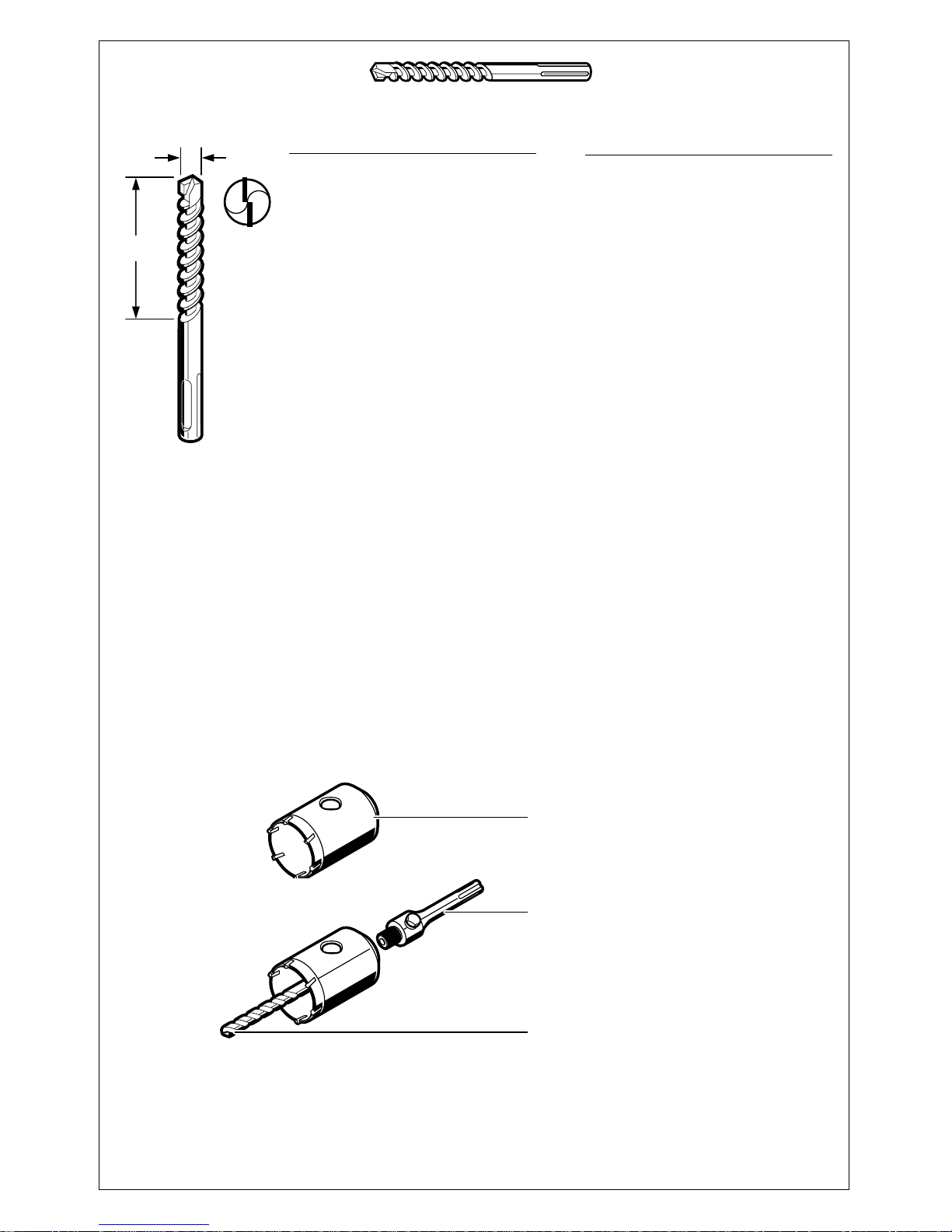
Ø 40 mm 2 608 550 074
Ø 50 mm 2 608 550 075
Ø 68 mm 2 608 550 076
L = 110 mm 2 608 550 057
Ø 8 mm 2 608 596 157
L
ø
10 950 2 608 597 122
12 550 1 618 596 224
12 950 2 608 597 123
14 550 1 618 596 225
14 950 2 608 597 124
15 400 1 618 596 257
16 150 1 618 596 201
16 250 1 618 596 258
16 400 1 618 596 259
16 550 1 618 596 226
16 750 1 618 596 227
16 950 2 608 597 125
17 150 1 618 596 203
18 150 1 618 596 204
18 250 1 618 596 319
18 400 1 618 596 260
18 550 2 608 596 120
18 750 2 608 596 122
18 950 2 608 597 126
19 150 1 618 596 205
19 250 1 618 596 320
19 400 1 618 596 261
ØL
(mm) (mm)
20 150 1 618 596 207
20 250 1 618 596 262
20 400 1 618 596 263
20 550 1 618 596 321
20 950 2 608 597 127
22 200 1 618 596 232
22 400 1 618 596 233
22 550 2 608 596 123
22 750 2 608 596 124
22 950 2 608 597 128
23 200 1 618 596 234
24 200 1 618 596 236
24 400 1 618 596 237
25 200 1 618 596 238
25 400 1 618 596 239
25 950 2 608 597 129
26 200 1 618 596 240
26 400 1 618 596 241
26 750 2 608 596 147
ØL
(mm) (mm)
4 • 1 619 929 236 • 02.06
SDS
plus
SDS
plus
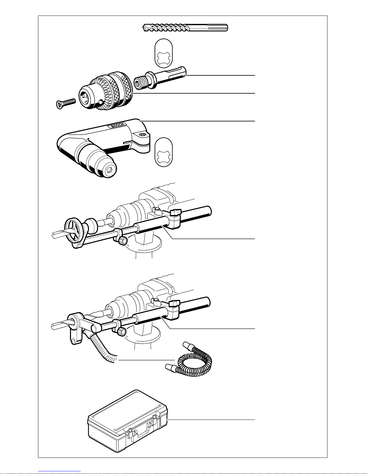
1 617 000 132
1 608 571 062
1 618 580 000
1 618 190 006
(Controller)
1 607 000 173
(Saugfix-Set)
3 m 2 600 793 009
5 m 1 610 793 002
2 605 438 294
420 x 280 x 110 mm
5 • 1 619 929 236 • 02.06
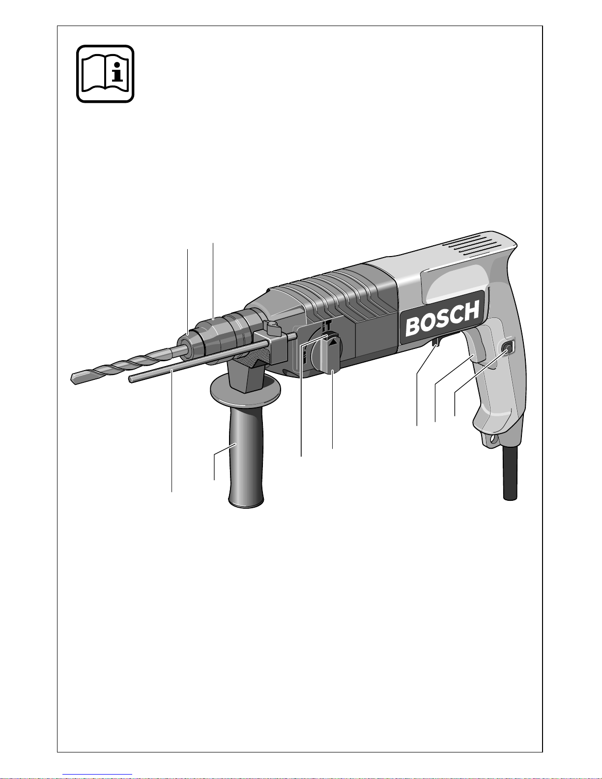
1
2
3
4
5
6
7
8
9
GBH 2 S
GBH 2 SE
GBH 2 SR

Deutsch - 1
1 Staubschutzkappe
2
Verriegelungshülse
3
Feststellknopf für Ein-/Ausschalter
4
Ein-/Ausschalter
5
Drehrichtungsumschalter (GBH 2 SR)
6
Schlagstoppschalter
7
Entriegelungsknopf
8
Zusatzgriff
9
Tiefenanschlag
Abgebildetes oder beschriebenes Zubehör gehört
teilweise nicht zum Lieferumfang.
Messwerte ermittelt entsprechend EN 50 144.
Der A-bewertete Geräuschpegel des Gerätes be-
trägt typischerweise:
Schalldruckpegel 88 dB (A);
Schallleistungspegel 101 dB (A).
Gehörschutz tragen!
Die bewertete Beschleunigung beträgt typischerweise 11 m/s
2
.
Das Gerät ist bestimmt zum Hammerbohren in
Beton, Ziegel und Gestein. Es ist ebenso geeignet zum Bohren ohne Schlag in Holz, Metall, Keramik und Kunststoff. Geräte mit elektronischer
Regelung und Rechts-/Linkslauf sind auch geeignet zum Schrauben und Gewindeschneiden.
Gerätekennwerte
Bohrhammer GBH 2 S GBH 2 SE GBH 2 SR
Bestellnummer 0 611 226 0.. 0 611 226 5.. 0 611 226 8..
Nennaufnahme [W] 620 620 620
Abgabeleistung [W] 360 360 360
Drehzahlsteuerung – • •
Rechts-/Linkslauf – – •
Nenndrehzahl
- Rechtslauf [min
-1
] 870 0–870 0–870
- Linkslauf [min
-1
] – – 0–500
Schlagzahl [/min] 4850 0–4850 0–4850
Einzelschlagstärke [J] 2,2 2,2 2,2
Werkzeugaufnahme SDS-plus SDS-plus SDS-plus
Spindelhals Ø [mm] 43 43 43
Bohrleistung:
- Mauerwerk (Hohlbohrkrone), max. [mm] 65 65 65
- Beton (Wendelbohrer) [mm] 4–24 4–24 4–24
- Holz, max. [mm] 30 30 30
- Stahl, max. [mm] 13 13 13
Gewicht (ohne Zubehör), ca. [kg] 2,4 2,4 2,4
Schutzklasse
/ II / II / II
Bitte die Bestellnummer Ihrer Maschine beachten. Die Handelsbezeichnungen einzelner Maschinen können variieren.
Geräteelemente Geräusch-/Vibrationsinformation
Bestimmungsgemäßer Gebrauch
6 • 1 619 929 236 • TMS • 13.06.02

Deutsch - 2
Gefahrloses Arbeiten mit dem
Gerät ist nur möglich, wenn Sie
die Bedienungsanleitung und
die Sicherheitshinweise vollständig lesen und die darin enthaltenen Anweisungen strikt befolgen. Zusätzlich müssen die
allgemeinen Sicherheitshinweise im beigefügten Heft befolgt werden. Lassen Sie sich
vor dem ersten Gebrauch praktisch einweisen.
■
Schutzbrille und Gehörschutz tragen.
■
Bei langen Haaren Haarschutz tragen. Nur mit
enganliegender Kleidung arbeiten.
■
Wird bei der Arbeit das Netzkabel beschädigt
oder durchtrennt, Kabel nicht berühren, sondern sofort den Netzstecker ziehen. Gerät niemals mit beschädigtem Kabel benutzen.
■
Geräte, die im Freien verwendet werden, über
einen Fehlerstrom-Schutzschalter (FI-) mit
maximal 30 mA Auslösestrom anschließen.
Nur ein für den Außenbereich zugelassenes
Verlängerungskabel verwenden.
■
Kabel immer nach hinten vom Gerät wegführen.
■
Gerät nicht am Kabel tragen oder aufhängen.
■
Stecker nur bei ausgeschaltetem Gerät in die
Steckdose einstecken.
■
Gerät nur mit Zusatzgriff 8 verwenden.
■
Verwenden Sie geeignete Suchgeräte, um
verborgene Versorgungsleitungen aufzuspüren, oder ziehen Sie die örtliche Versorgungsgesellschaft hinzu.
Kontakt mit Elektroleitungen kann zu Feuer
und elektrischem Schlag führen. Beschädigung einer Gasleitung kann zur Explosion
führen. Eindringen in eine Wasserleitung verursacht Sachbeschädigung oder kann einen
elektrischen Schlag verursachen.
■
Das Elektrowerkzeug nur an isolierten
Handgriffen anfassen, wenn das Einsatzwerkzeug eine verborgene Leitung oder
das eigene Netzkabel treffen kann.
Kontakt mit einer spannungsführenden Leitung kann Metallteile des Gerätes unter Spannung setzen und zu einem elektrischen Schlag
führen.
■
Beim Arbeiten das Gerät immer fest mit beiden
Händen halten und für einen sicheren Stand
sorgen.
■
Gerät nur ausgeschaltet auf die Mutter/
Schraube aufsetzen.
■
Beim Schrauben im 1. Gang bzw. mit kleiner
Drehzahl arbeiten.
■
Vorsicht beim Eindrehen langer Schrauben,
Abrutschgefahr.
■
Das Gerät vor dem Ablegen immer ausschalten und warten bis das Gerät zum Stillstand
gekommen ist.
■
Niemals Kindern die Benutzung des Gerätes
gestatten.
■
Bosch kann nur dann eine einwandfreie Funktion des Gerätes zusichern, wenn das für dieses Gerät vorgesehene Original-Zubehör verwendet wird.
■
Gerät nur mit Zusatzgriff 8 verwenden.
Das Griffstück durch Linksdrehen lösen. Den Zusatzgriff
8
schwenken und der Arbeitsstellung
anpassen.
Das Griffstück danach wieder fest anziehen.
Mit dem Tiefenanschlag 9 kann die Bohrtiefe eingestellt werden.
Die Riffelung am Tiefenanschlag
9
muss nach
oben zeigen.
■
Vor allen Arbeiten am Gerät Netzstecker
ziehen.
Mit der Werkzeugaufnahme SDS-plus ist ein einfacher, bequemer Werkzeugwechsel möglich,
ohne Hilfe zusätzlicher Werkzeuge.
☞
Das Einsteckende der Werkzeuge ist regelmäßig zu fetten.
Die Staubschutzkappe 1 verhindert weitgehend
das Eindringen von Bohrstaub während des Betriebes. Beim Einsetzen des Werkzeuges darauf
achten, dass die Staubschutzkappe
1
nicht be-
schädigt wird.
Eine beschädigte Staubschutzkappe ist sofort auszutauschen. Es wird empfohlen, dies
von einem Kundendienst vornehmen zu lassen.
☞
Systembedingt muss das SDS-plus-Werkzeug frei beweglich sein. Dadurch entsteht
beim Leerlauf eine Rundlaufabweichung.
Dies hat keine Auswirkungen auf die Genauigkeit des Bohrlochs, da sich der Bohrer beim Bohren selbsttätig zentriert.
Zu Ihrer Sicherheit
Zusatzgriff/Tiefenanschlag
Werkzeugwechsel
7 • 1 619 929 236 • TMS • 13.06.02
Deutsch - 3
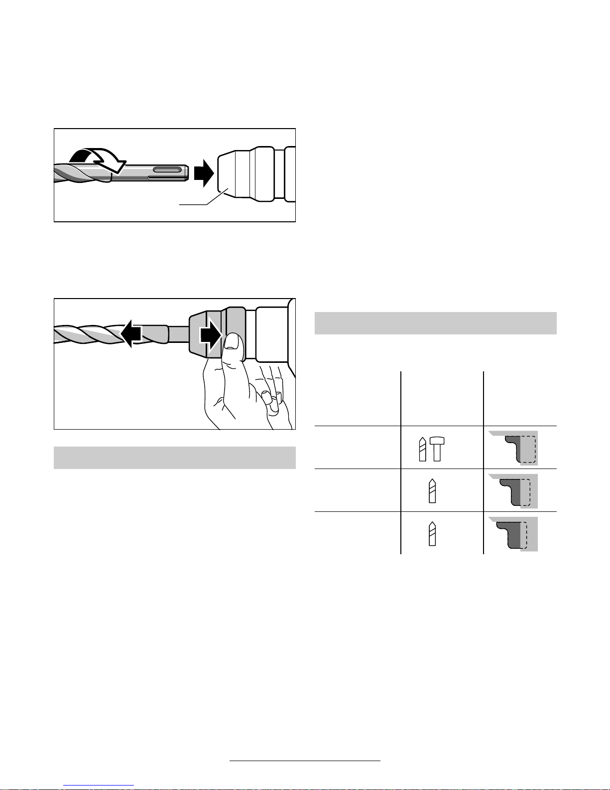
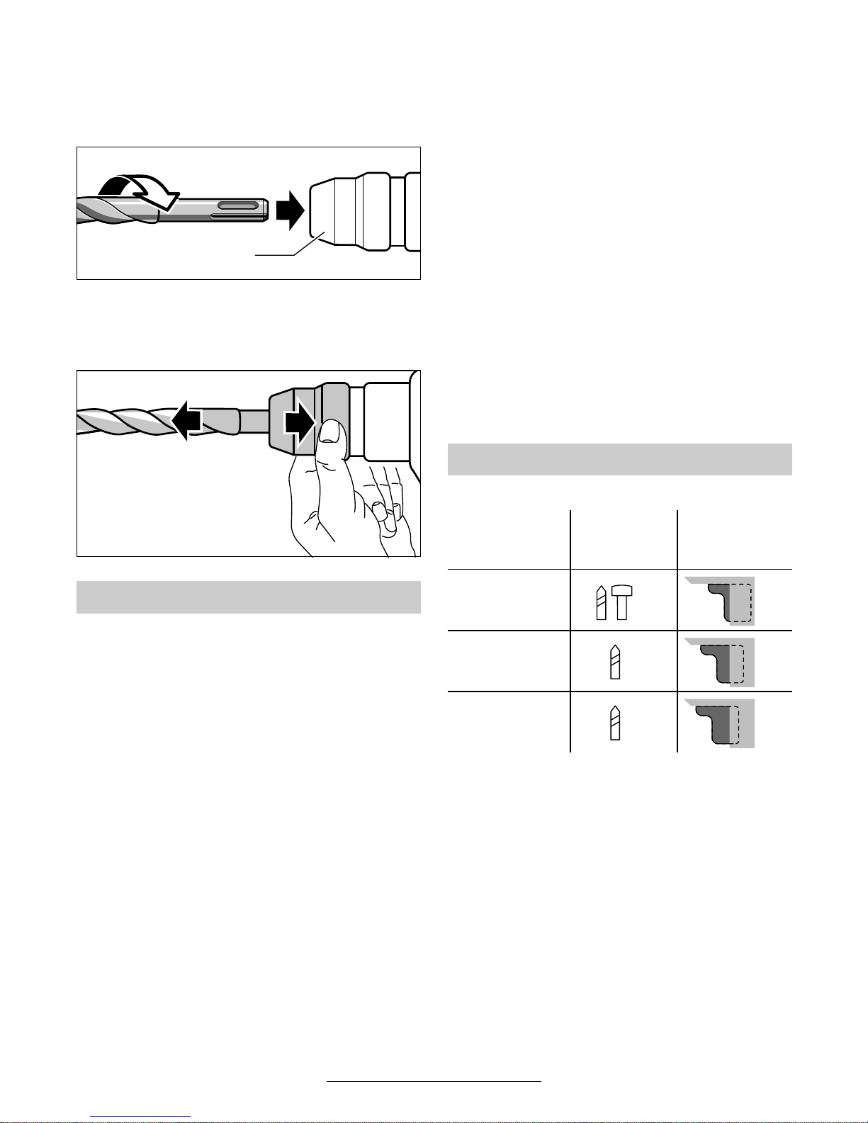
Einsetzen
Das Einsteckende des Werkzeuges reinigen
und fetten.
Das Werkzeug drehend in die Werkzeugaufnahme einführen bis es selbsttätig verriegelt
wird. Die Verriegelung durch Ziehen am Werkzeug prüfen.
Entnehmen
Die Verriegelungshülse 2 der Werkzeugaufnahme nach hinten schieben und das Werkzeug
entnehmen.
Netzspannung beachten: Die Spannung der
Stromquelle muss mit den Angaben auf dem
Typschild des Gerätes übereinstimmen. Mit
230 V gekennzeichnete Geräte können auch an
220 V betrieben werden.
Ein-/Ausschalten
Zur Inbetriebnahme des Gerätes den Ein-/Ausschalter
4
drücken und gedrückt halten.
Zum
Feststellen den Ein-/Ausschalter 4 in ge-
drücktem Zustand mit dem Feststellknopf
3
arre-
tieren.
Zum
Ausschalten des Gerätes den Ein-/Aus-
schalter
4
loslassen bzw. drücken und loslassen.
Stufenlose Drehzahlregulierung
(GBH 2 SE/GBH 2 SR)
Die Maschine läuft je nach Druck auf den Ein-/
Ausschalter
4
mit variabler Drehzahl zwischen
0 und Maximum. Leichter Druck auf den Ein-/
Ausschalter
4
bewirkt eine kleine Drehzahl und
macht somit einen kontrollierten Anlauf möglich.
Mit zunehmenden Druck wird die Drehzahl erhöht.
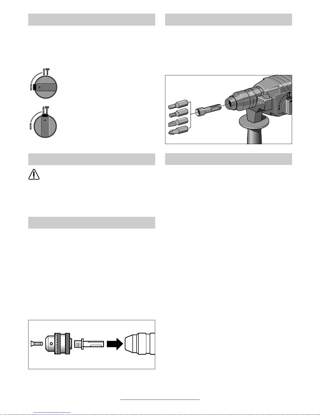
Umschalten der Drehrichtung
(GBH 2 SR)
Die Laufrichtung der Maschine kann durch den
Drehrichtungsumschalter
5
gewählt werden.
Zum besseren Lösen von vollständig eingedrehten Schraubverbindungen ist die Drehzahl im
Linkslauf auf 500 Umdrehungen/min begrenzt.
Der Ein-/Ausschalter
4
kann im Linkslauf aus
Sicherheitsgründen nicht mit dem Feststellknopf
3
arretiert werden.
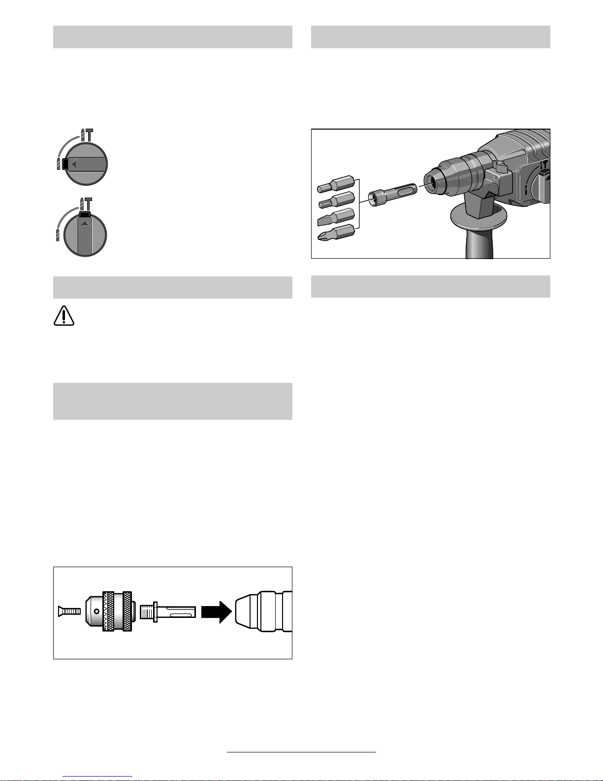
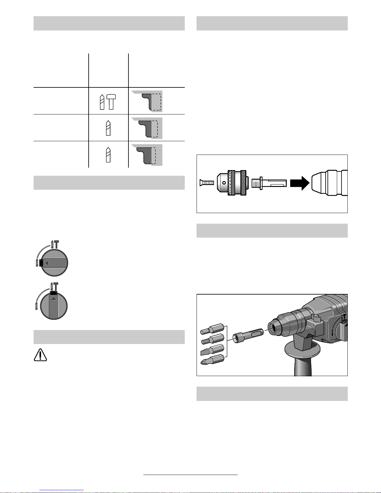
Die Angaben in der Tabelle sind empfohlene
Werte.
Inbetriebnahme
2
Drehzahltabelle
Anwendungsbereich
Schlagstoppschalter
Drehzahlsteuerung
GBH 2 SE/
GBH 2 SR
Schlagbohren
- Gestein/
Beton
Bohren
- Holz/Stahl
Schrauben
8 • 1 619 929 236 • TMS • 13.06.02
Deutsch - 4
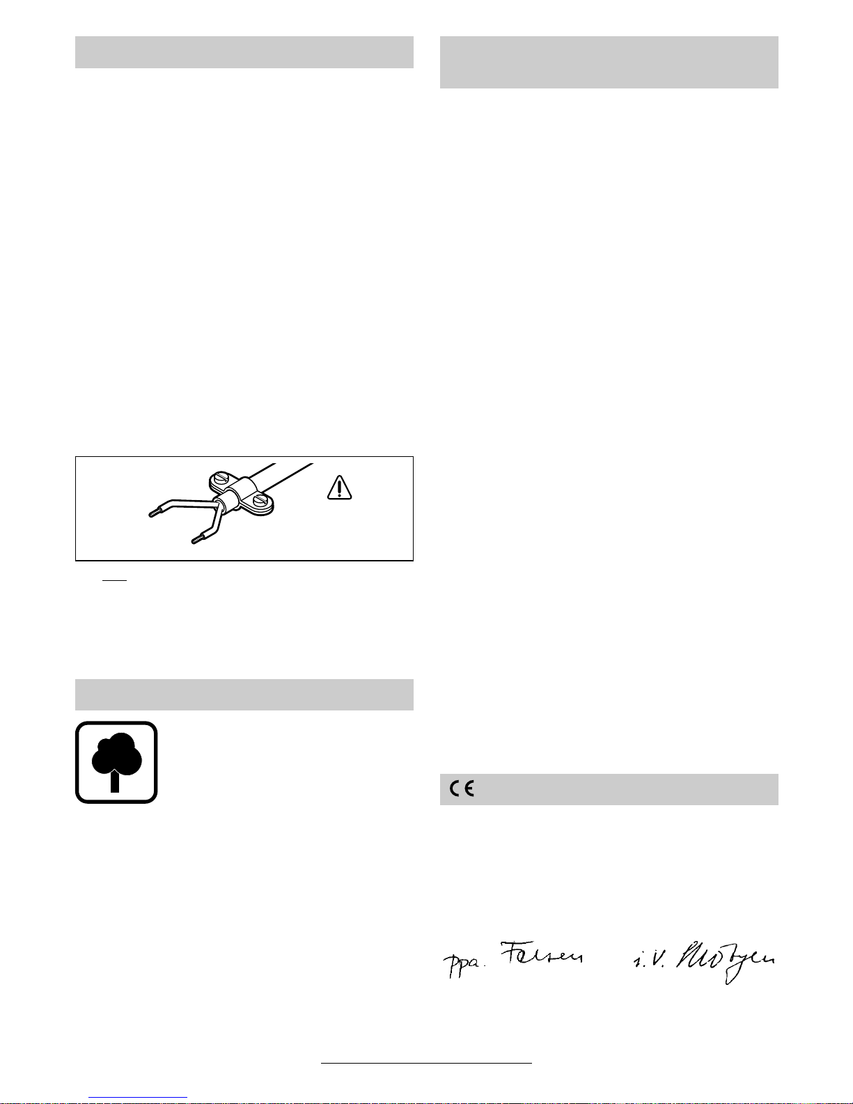
■ Den Schlagstoppschalter 6 nur im Still-
stand betätigen.
Den Entriegelungsknopf 7 drücken und gleich-
zeitig den Schlagstoppschalter 6 in die ge-
wünschte Stellung bringen.
Bohren
Hammerbohren
Klemmt oder hakt das Bohrwerkzeug, wird
der Antrieb zur Bohrspindel unterbrochen.
Wegen der dabei auftretenden Kräfte das
Gerät immer mit beiden Händen sicher
halten und einen festen Stand einnehmen.
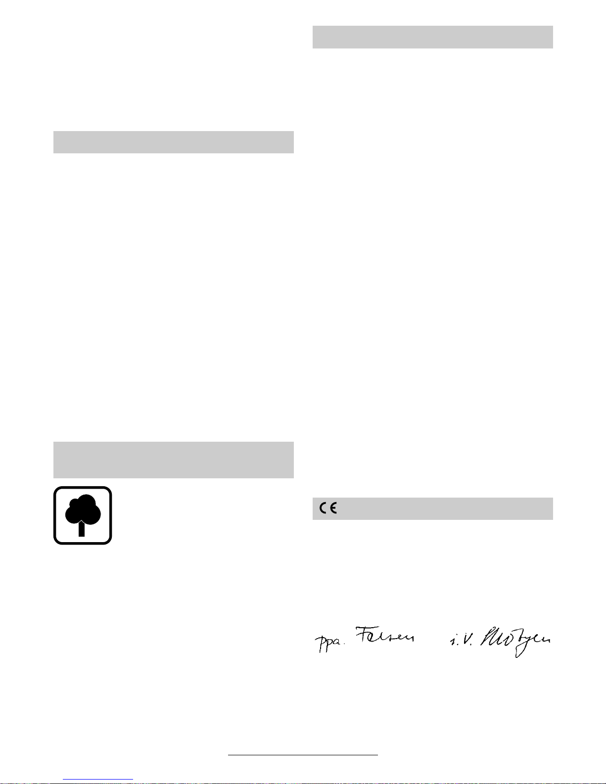
Mit dem Zahnkranz- bzw. Schnellspannbohrfutter (Zubehör) und dem zugehörigen Adapter (Zubehör) können Werkzeuge mit zylindrischem
Schaft eingespannt werden.
☞
Den Schlagstoppschalter 6 auf „Bohren“ stellen (nur im Stillstand betätigen).
Den Adapterschaft reinigen und leicht fetten.
Das zusammengesetzte Bohrfutter drehend in
die Werkzeugaufnahme einführen bis es einrastet; es verriegelt sich selbsttätig. Die Verriegelung durch Ziehen am Bohrfutter prüfen.
Zum Eindrehen von Schrauben muss der Universalbithalter mit SDS-plus-Schaft (Zubehör) verwendet werden.
– Die Laufrichtung auf Rechtslauf einstellen.
– Mit dem Ein-/Ausschalter 4 die Drehzahl re-
geln.
Die Staubabsaugung verhindert größere Verschmutzungen, hohe Staubbelastungen in
der Atemluft und erleichtert die Entsorgung.
Das Gerät kann direkt an die Steckdose eines
Bosch-Allzwecksaugers mit Fernstarteinrichtung
angeschlossen werden. Dieser wird beim Einschalten des Gerätes automatisch gestartet.
Saugfix
Den Saugfix (Zubehör) montieren und den
Staubsauger anschließen. Der Saugfix federt bis
zur vorbestimmten Bohrtiefe zurück. Dadurch
wird der Saugfix-Kopf immer dicht an der Oberfläche gehalten.
Schlagstoppschalter
Überlastkupplung
Bohrer mit zylindrischem Schaft
Schrauben (GBH 2 SR)
Staubabsaugung
9 • 1 619 929 236 • TMS • 13.06.02
Deutsch - 5
■ Vor allen Arbeiten am Gerät Netzstecker
ziehen.
☞
Gerät und Lüftungsschlitze stets sauber
halten, um gut und sicher zu arbeiten.
■ Werkzeugaufnahme immer sauber halten.
Eine beschädigte Staubschutzkappe ist so-
fort auszutauschen. Es wird empfohlen, dies
von einem Kundendienst vornehmen zu lassen.
Sollte das Gerät trotz sorgfältiger Herstellungsund Prüfverfahren einmal ausfallen, ist die Reparatur von einer autorisierten Kundendienststelle
für Bosch-Elektrowerkzeuge ausführen zu lassen.
Bei allen Rückfragen und Ersatzteilbestellungen
bitte unbedingt die 10-stellige Bestellnummer laut
Typenschild des Gerätes angeben.
Rohstoffrückgewinnung statt Müllentsorgung
Gerät, Zubehör und Verpackung sollten einer
umweltgerechten Wiederverwertung zugeführt
werden.
Diese Anleitung ist aus chlorfrei gefertigtem Recycling-Papier hergestellt.
Zum sortenreinen Recycling sind Kunststoffteile
gekennzeichnet.
In Deutschland sind nicht mehr gebrauchsfähige
Geräte zum Recycling beim Handel abzugeben
oder (ausreichend frankiert) direkt einzuschicken
an:
Recyclingzentrum Elektrowerkzeuge
Osteroder Landstraße 3
37589 Kalefeld
www.powertool-portal.de, das Internetportal
für Handwerker und Heimwerker
www.ewbc.de, der Informations-Pool für Handwerk und Ausbildung
Deutschland
Robert Bosch GmbH
Servicezentrum Elektrowerkzeuge
Zur Luhne 2
D-37589 Kalefeld
✆ Service: ....................................... 01 80 - 3 35 54 99
Fax
............................................. +49 (0) 55 53 / 20 22 37
✆ Kundenberater:...................... 01 80 - 3 33 57 99
Österreich
ABE Service GmbH
Jochen-Rindt-Straße 1
A-1232 Wien
✆ Service: ..................................... +43 (0)1 / 61 03 80
Fax
................................................. +43 (0)1 / 61 03 84 91
✆ Kundenberater:............ +43 (0)1 / 797 22 3066
E-Mail: abe@abe-service.co.at
Schweiz
Robert Bosch AG
Kundendienst Elektrowerkzeuge
Industriestrasse 31
CH-8112 Otelfingen
✆ Service: ................................. +41 (0)1 / 8 47 16 16
✆ Kundenberater:...... Grüne Nr. 0 800 55 11 55
Wir erklären in alleiniger Verantwortung, dass
dieses Produkt mit den folgenden Normen oder
normativen Dokumenten übereinstimmt:
EN 50 144 gemäß den Bestimmungen der Richtlinien 89/336/EWG, 98/37/EG.
Dr. Gerhard Felten Dr. Eckerhard Strötgen
Entwicklungsleiter Leiter Produktzulassung
Robert Bosch GmbH, Geschäftsbereich Elektrowerkzeuge
Änderungen vorbehalten
Wartung und Reinigung
Umweltschutz
Service und Kundenberater
Konformitätserklärung
10 • 1 619 929 236 • TMS • 13.06.02

English - 1
1 Dust protection cap
2 Locking sleeve
3 Lock-on button for On/Off switch
4 On/Off switch
5 Rotational direction switch (GBH 2 SR)
6 Impact stop switch
7 Release button
8 Auxiliary handle
9 Depth stop
Not all of the accessories illustrated or described are
included as standard delivery.
Measured values determined according to
EN 50 144.
Typically the A-weighted noise levels of the product are: sound pressure level: 88 dB (A); sound
power level: 101 dB (A).
Wear hearing protection!
The typically weighted acceleration is 11 m/s
2
.
The machine is intended for hammer drilling in
concrete, brick and stone. It is also suitable for
drilling without impact in wood, metal, ceramic
and plastic. Machines with electronic control and
right /left rotation are also suitable for screwdriving and thread cutting.
Tool Specifications
Rotary Hammer GBH 2 S GBH 2 SE GBH 2 SR
Order number 0 611 226 0.. 0 611 226 5.. 0 611 226 8..
Rated power [W] 620 620 620
Output power [W] 360 360 360
Speed control – • •
Right/Left rotation – – •
Rated speed
- Right rotation [rpm] 870 0–870 0– 870
- Left rotation [rpm] – – 0–500
Impact rate [bpm] 4850 0–4850 0–4850
Impact energy per stroke [J] 2.2 2.2 2.2
Tool holder SDS-plus SDS-plus SDS-plus
Spindle collar diameter Ø [mm] 43 43 43
Drilling output:
- Masonry (core bit), max. [mm] 65 65 65
- Concrete (twist drill bit) [mm] 4–24 4–24 4–24
- Wood, max. [mm] 30 30 30
- Steel, max. [mm] 13 13 13
Weight (without accessories), approx. [kg] 2.4 2.4 2.4
Protection class / II / II / II
Please observe the order number of your machine. The trade names of the individual machines may vary.
Machine Elements Noise/Vibration Information
Intended Use
11 • 1 619 929 236 • TMS • 13.06.02

English - 2
Working safely with this machine is possible only when the
operating and safety information
are read completely and the instructions contained therein are
strictly followed. In addition, the
general safety notes in the enclosed booklet must be observed. Before using for the first
time, ask for a practical demonstration.
■ Wear protective glasses and hearing protection.
■ For long hair, wear hair protection. Work only
with closely fitting clothes.
■ If the mains cable is damaged or cut through
while working, do not touch the cable but immediately pull the mains plug. Never use the
machine with a damaged cable.
■ Connect machines that are used in the open
via a residual current device (RCD) with an actuating current of 30 mA maximum. Use only
extension cables that are approved for outdoor
use.
■ Always direct the cable to the rear away from
the machine.
■ Do not carry or hang up the machine by the cable.
■ Insert the mains plug only when the machine is
switched off.
■ Use the machine only with the auxiliary handle 8.
■ Use appropriate detectors to determine if
utility lines are hidden in the work area or
call the local utility company for assistance.
Contact with electric lines can lead to fire and
electric shock. Damaging a gas line can lead
to explosion. Penetrating a water line causes
property damage or may cause an electric
shock.
■ Hold the power tool only by the insulated
gripping surfaces, when performing an operation where the cutting tool may run into
hidden wiring or its own cord.
Contact with a “live” wire will make exposed
metal parts of the tool “live” and shock the operator.
■ When working with the machine, always hold it
firmly with both hands and provide for a secure
stance.
■ Set the machine against the screw/nut only
when switched off.
■ When screwdriving, operate in first gear as
well as with a low speed.
■ Be careful when screwing in long screws; danger of sliding off.
■ Always switch the machine off and wait until it
has come to a standstill before placing it down.
■ Never allow children to use the machine.
■ Bosch is only able to ensure perfect operation
of the machine if the original accessories intended for it are used.
■ Use the machine only with the auxiliary
handle 8.
Loosen the handle by turning to the left. Rotate
the auxiliary handle 8 and adapt to the working
position.
Firmly retighten the handle.
The drilling depth can be set with the depth
stop 9.
The ribbing on depth stop 9 must point upwards.
■ Before any work on the machine itself, pull
the mains plug.
With the SDS-plus tool holder, simpler and easier
tool changing is possible without additional aids.
☞
Grease the shank end of the tool regularly.
The dust protection cap 1 largely prevents the
entry of drilling dust during operation. When inserting the tool, take care that the dust protection
cap 1 is not damaged.
A damaged dust protection cap should be
changed immediately. We recommend having
this carried out by an after-sales service.
☞
As a requirement of the system, the
SDS-plus tool must rotate freely. At no-load
speed, this leads to a certain amount of radial run-out.
This does not affect the accuracy of the drill
hole, as the bit is automatically centred during drilling.
For Your Safety
Auxiliary Handle/Depth Stop
Changing the Tool
12 • 1 619 929 236 • TMS • 13.06.02
English - 3
Inserting
Clean and grease the shank end of the tool.
Insert the tool in a twisting manner into the tool
holder until it locks. Check if it has locked by pulling the tool.
Removing
Push back the locking sleeve 2 of the tool holder
and remove the tool.
Observe correct mains voltage: The voltage of
the power source must agree with the voltage
specified on the nameplate of the machine.
Equipment marked with 230 V can also be connected to 220 V.
Switching On and Off
To start the machine, press the On/ Off switch 4
and keep it depressed.
Lock the pushed On/Off switch 4 by pressing the
lock-on button 3.
To switch off the machine, release the On / Off
switch 4 or push and release it then.
Stepless Speed Control
(GBH 2 SE/ GBH 2 SR)
The machine runs with variable speed between 0
and maximum, depending on the pressure applied to the On /Off switch 4. Light pressure on
the On/Off switch 4 results in low rotational
speed, thus allowing drilling to begin in a smooth,
controlled manner. Further pressure on the
switch results in an increase in speed.
Reversing the Rotational Direction
(GBH 2 SR)
The direction of rotation of the machine can be
selected with the reversing switch 5.
For better loosening of completely screwed in
threaded connections, the speed in left rotation is
limited to 500 RPM.
For safety reasons in left rotation, the on/off
switch 4 cannot be locked with the locking but-
ton 3.
The values in the table are recommendations.
Initial Operation
2
Speed Table
Area of
Application
Impact Stop
Switch
Speed control
GBH 2 SE/
GBH 2 SR
Impact Drilling
- Stone/
Concrete
Drilling
- Wood/Steel
Screwdriving
13 • 1 619 929 236 • TMS • 13.06.02
English - 4
■ Operate the impact stop switch 6 only
when at a standstill.
Press the release button 7 and, at the same time,
set the impact stop switch 6 to the desired position.
Drilling
Hammer drilling
If the drill bit jams or edges, the drive to the
drill spindle is interrupted.
Due to the arising forces always hold the
machine firmly with both hands and
provide for a secure stance.
With the key or keyless chuck (accessory) and
the associated adapter (accessory), tools with cylindrical shafts can be mounted.
☞
Set the impact stop switch 6 to “Drilling” (only at a standstill).
Clean and lightly grease the adapter shank.
Insert the assembled chuck with a twisting man-
ner into the tool holder until it latches. The chuck
locks itself. Check the locking by pulling on the
chuck.
For screwdriving, the universal bit holder with
SDS-plus shank (accessory) must be used.
– Set the direction of rotation to right-hand rota-
tion.
– Regulate the speed with the On/Off switch 4.
The dust extraction keeps the work area
clean, prevents high dust contamination of
the breathing air and makes the disposal easier.
The machine can be plugged directly into the receptacle of a Bosch all-purpose vacuum cleaner
with remote control starting. The vacuum cleaner
starts automatically when the machine is
switched on.
Dust Extraction Attachment
Mount the dust extraction attachment (accessory) and connect the vacuum cleaner. The dust
extraction attachment springs back to the predetermined drilling depth, which allows for close
seating of the attachment head to the surface.
Impact Stop Switch
Overload Clutch
Drill Bits with Cylindrical
Shanks
Screwdriving (GBH 2 SR)
Dust extraction
14 • 1 619 929 236 • TMS • 13.06.02
English - 5
■ Before any work on the machine itself, pull
the mains plug.
☞
For safe and proper working, always keep
the machine and the ventilation slots clean.
■ Keep the tool holder clean at all times.
A damaged dust protection cap should be
changed immediately. We recommend having
this carried out by an after-sales service.
If the machine should fail despite the care taken
in manufacturing and testing procedures, repair
should be carried out by an after-sales service
centre for Bosch power tools.
In all correspondence and spare parts orders,
please always include the 10-digit order number
given on the nameplate of the machine.
WARNING! Important instructions for connecting a new 3-pin plug to the 2-wire cable.
The wires in the cable are coloured according to
the following code:
Do not
connect the blue or brown wire to the
earth terminal of the plug.
Important: If for any reason the moulded plug is
removed from the cable of this machine, it must
be disposed of safely.
Recycle raw materials instead of disposing as
waste
The machine, accessories and packaging should
be sorted for environmental-friendly recycling.
These instructions are printed on recycled paper
manufactured without chlorine.
The plastic components are labelled for categorized recycling.
Great Britain
Robert Bosch Ltd. (B.S.C.)
P.O. Box 98
Broadwater Park
North Orbital Road
Denham-Uxbridge
GB-Middlesex UB 9 5HJ
✆ Service............................ +44 (0)18 95 / 83 87 82
✆ Advice line.................... +44 (0)18 95 / 83 87 91
Fax
............................................. +44 (0)18 95 / 83 87 89
Ireland
Beaver Distribution Ltd.
Greenhills Road
IRL-Tallaght-Dublin 24
✆ Service................................... +353 (0)1 / 414 9400
Fax
.................................................... +353 (0)1 / 459 8030
Australia
Robert Bosch Australia L.t.d.
RBAU/SPT2
1555 Centre Road
P.O. Box 66 Clayton
AUS-3168 Clayton/Victoria
✆ ............................................... +61 (0)1 / 800 804 777
Fax
............................................... +61 (0)1 / 800 819 520
www.bosch.com.au
E-Mail: CustomerSupportSPT@au.bosch.com
New Zealand
Robert Bosch Limited
14-16 Constellation Drive
Mairangi Bay
Auckland
New Zealand
✆ ..................................................... +64 (0)9 / 47 86 158
Fax
..................................................... +64 (0)9 / 47 82 914
We declare under our sole responsibility that this
product is in conformity with the following
standards or standardization documents:
EN 50 144 according to the provisions of the directives 89/336/EEC, 98/37/EC.
Dr. Gerhard Felten Dr. Eckerhard Strötgen
Senior Vice President Engineering Head of Product Certification
Robert Bosch GmbH, Geschäftsbereich Elektrowerkzeuge
Subject to change without notice
Maintenance and Cleaning
Environmental Protection
strain relief
live = brown
neutral = blue
To be fitted
by qualified
professional only
Service and Customer
Assistance
Declaration of Conformity
15 • 1 619 929 236 • TMS • 13.06.02

Français - 1
1 Capuchon anti-poussière
2 Douille de verrouillage
3 Bouton de verrouillage de l’interrupteur
Marche/Arrêt
4 Interrupteur Marche/Arrêt
5 Commutateur du sens de rotation
(GBH 2 SR)
6 Stop de frappe
7 Touche de déverrouillage
8 Poignée supplémentaire
9 Butée de profondeur
Les accessoires reproduits ou décrits ne sont pas
forcément fournis avec la machine.
Valeurs de mesure obtenues conformément à la
norme européenne 50 144.
Les mesures réelles (A) des niveaux sonores de
la machine sont : intensité de bruit 88 dB (A).
Niveau de bruit 101 dB (A).
Munissez-vous d’une protection acoustique !
L’accélération réelle mesurée est de 11 m/s
2
.
Cet outillage a été conçu pour perforer le béton,
la brique ou la pierre. Il peut également sans inconvénient être utilisé pour percer le bois, les
métaux, la céramique ou les plastiques si le dispositif de frappe a été désactivé. Les appareils
munis d’un variateur électronique autorisant une
rotation dans les deux sens (droite/gauche) peuvent également servir pour visser ou tarauder.
Caractéristiques techniques
Marteau perforateur GBH 2 S GBH 2 SE GBH 2 SR
Référence 0 611 226 0.. 0 611 226 5.. 0 611 226 8..
Puissance absorbée [W] 620 620 620
Puissance débitée [W] 360 360 360
Réglage de la vitesse de rotation – • •
Rotation à droite/à gauche – – •
Régime nominal
- Rotation à droite [tr/min] 870 0 – 870 0 –870
- Rotation à gauche [tr/min] – – 0–500
Fréquence de frappe [tr/min] 4850 0– 4850 0– 4850
Travail par coup [J] 2,2 2,2 2,2
Fixation de l’outil SDS-plus SDS-plus SDS-plus
Collet de broche Ø [mm] 43 43 43
Puissance de perçage :
- Maçonnerie (Couronnes trépans), max. [mm] 65 65 65
- Béton (Foret hélicoïdal) [mm] 4–24 4–24 4–24
- Bois, max. [mm] 30 30 30
- Acier, max. [mm] 13 13 13
Poids (sans accessoires), env. [kg] 2,4 2,4 2,4
Classe de protection / II / II / II
Faire attention au numéro de référence de la machine. Les désignations commerciales des différentes machines
peuvent varier.
Eléments de la machine Bruits et vibrations
Utilisation conformément à la
destination de l’appareil
16 • 1 619 929 236 • TMS • 13.06.02

Français - 2
Pour travailler sans risque avec
cet appareil, lire intégralement
au préalable les instructions
d’utilisation et les remarques
concernant la sécurité. Respecter scrupuleusement les indications et les consignes qui y sont
données. Respecter en plus les
indications générales de sécurité se trouvant dans le cahier
ci-joint. Avant la première mise
en service, laisser quelqu’un
connaissant bien cet appareil
vous indiquer la façon de s’en
servir.
■ Porter des lunettes de sécurité et une protection acoustique.
■ Les personnes portant les cheveux longs doivent se munir d’un protège-cheveux. Ne travailler qu’avec des vêtements près du corps.
■ Si le câble d’alimentation électrique est endommagé ou se rompt pendant le travail, ne
pas y toucher. Retirer immédiatement la fiche
du câble d’alimentation de la prise de courant.
Ne jamais utiliser un appareil dont le cordon
d’alimentation est endommagé.
■ Monter un disjoncteur différentiel (courant de
déclenchement : 30 mA max.) en amont des
appareils utilisés en plein air. N’utiliser qu’un
câble de rallonge électrique autorisé pour les
travaux à l’extérieur.
■ Toujours ramener les câbles à l’arrière de l’appareil.
■ Ne jamais porter ou suspendre l’appareil par
son cordon d’alimentation.
■ Ne brancher l’appareil que si celui-ci est en position « Arrêt ».
■ N’utiliser l’appareil qu’avec la poignée supplémentaire 8.
■ Utiliser des détecteurs appropriés afin de
déceler des conduites cachées ou consulter les entreprises d’approvisionnement locales.
Un contact avec des conduites d’électricité
peut provoquer un incendie ou un choc électrique. Un endommagement d’une conduite de
gaz peut provoquer une explosion. La perforation d’une conduite d’eau provoque des dégâts
matériels et peut provoquer un choc électrique.
■ Ne tenir l’outil électrique que par les poi-
gnées isolées lorsqu’il y a risque que l’outil
électrique puisse toucher une conduite cachée ou son propre câble d’alimentation.
Le contact avec une conduite sous tension
peut mettre les parties métalliques de l’appareil sous tension et provoquer ainsi un choc
électrique.
■ Pendant le travail avec cet appareil, le tenir
toujours fermement avec les deux mains.
Adopter une position stable et sûre.
■ N’appliquer l’appareil sur un écrou ou une vis
que lorsqu’il est à l’arrêt.
■ Visser en 1ère ou avec une vitesse de rotation
réduite.
■ Attention lors de la pose des vis longues : elles
peuvent glisser.
■ Avant de déposer l’appareil, toujours le mettre
hors fonctionnement et attendre l’arrêt total de
l’appareil.
■ Ne jamais permettre aux enfants d’utiliser cet
appareil.
■ Bosch ne peut garantir un fonctionnement impeccable que si les accessoires Bosch d’origine prévus pour cet appareil sont utilisés.
■ N’utiliser l’appareil qu’avec la poignée supplémentaire 8.
Imprimer au manche de la poignée une rotation
vers la gauche. Faire pivoter la poignée supplémentaire 8 et la régler en fonction de la position
de travail.
Bien resserrer le manche de la poignée supplémentaire.
La butée de profondeur 9 permet de régler la profondeur de perçage.
Les cannelures de la butée de profondeur 9 doivent être tournées vers le haut.
Pour votre sécurité
Poignée supplémentaire/
Butée de profondeur
17 • 1 619 929 236 • TMS • 13.06.02
Français - 3
■ Avant toute intervention sur l’appareil pro-
prement dit, toujours retirer la fiche du câble d’alimentation de la prise de courant.
Grâce au système de fixation SDS-plus, le changement de l’outil est facile et rapide et ne nécessite pas d’outils supplémentaires.
☞
Graisser la queue des outils à intervalles réguliers.
Le capuchon anti-poussière 1 empêche dans
une large mesure une pénétration de poussières
durant le travail. Lors du montage de l’outil, veiller
à ce que le capuchon anti-poussière 1 ne soit
pas endommagé.
Remplacer immédiatement un capuchon
anti-poussière endommagé. Il est recommandé de faire effectuer ce travail par un
service après-vente.
☞
De par sa construction, l’outil SDS-plus doit
pouvoir bouger librement. Pour cette raison, un faux-rond se crée pendant que
l’appareil tourne à vide.
Ceci n’a aucun effet sur la précision du trou
de perçage étant donné que le foret se centre automatiquement pendant le perçage.
Montage
Nettoyer et graisser la queue de l’outil.
Par un mouvement de rotation, introduire l’outil
dans le porte-outil jusqu’à ce qu’il soit verrouillé
automatiquement. Contrôler s’il est bien verrouillé en tirant sur l’outil.
Démontage de l’outil
Pousser en arrière la douille de verrouillage 2 du
porte-outil et retirer l’outil.
Tenir compte de la tension du secteur : La tension de la source de courant doit correspondre aux
indications figurant sur la plaque signalétique de
l’appareil. Les appareils fonctionnant sous 230 V
peuvent également être exploités sous 220 V.
Mise en fonctionnement/Arrêt
Afin de mettre l’appareil en fonctionnement,
appuyer sur l’interrupteur Marche/Arrêt 4 et le
maintenir appuyé.
Afin de le bloquer, bloquer l’interrupteur Marche/
Arrêt 4 dans cette position à l’aide du bouton de
blocage de fonctionnement 3.
Afin d’arrêter l’appareil, relâcher l’interrupteur
Marche/Arrêt 4 ou appuyer sur l’interrupteur et le
relâcher.
Réglage en continu de la vitesse
(GBH 2 SE/ GBH 2 SR)
En fonction de la pression exercée sur l’interrupteur Marche/Arrêt 4, l’appareil fonctionne à une
vitesse comprise entre 0 et le maximum. Une légère pression sur l’interrupteur Marche/Arrêt 4
permet d’obtenir une faible vitesse de rotation, et
donc un démarrage progressif, facilement contrôlable. Une pression plus forte entraîne une augmentation de la vitesse.
Inversion du sens de rotation
(GBH 2 SR)
Il est possible de sélectionner le sens de rotation
de l’appareil à l’aide du commutateur de sens de
rotation 5.
Afin de mieux desserrer les vis profondément enfoncées, la vitesse de rotation est limitée à
500 tours/min pour le régime de rotation à gauche.
Pour des raisons de sécurité, il n’est pas possible
de bloquer l’interrupteur Marche/Arrêt 4 à l’aide
du bouton de verrouillage 3 lorsqu’on travaille en
régime de rotation à gauche.
Changement de l’outil
2
Mise en service
18 • 1 619 929 236 • TMS • 13.06.02
Français - 4
Les indications se trouvant dans le tableau ciaprès sont des valeurs recommandées.
■ Le stop de frappe 6 ne doit être activé qu’à
l’arrêt total de la machine.
Appuyer sur le bouton de déverrouillage 7 et en
même temps, mettre le stop de frappe 6 dans la
position désirée.
Perçage
Perçage en frappe
Si l’outil de perçage se coince ou reste bloqué dans le matériau, l’entraînement de la
broche est immédiatement interrompu.
En raison des forces pouvant en résulter,
toujours bien tenir l’appareil des deux
mains, veiller à garder une position stable et équilibrée.
Il est possible de serrer des outils à queue cylindrique au moyen du mandrin de perçage à couronne dentée ou à serrage rapide (accessoires)
et de l’adaptateur correspondant (accessoire).
☞
Mettre le stop de frappe 6 sur la position « Perçage » (ne l’activer qu’à l’arrêt total de la machine).
Nettoyer la queue de l’adaptateur et la graisser
légèrement.
Une fois le mandrin de perçage assemblé, l’introduire par un mouvement de rotation dans le porteoutil jusqu’à ce qu’il s’encliquette; il est alors automatiquement verrouillé. Contrôler s’il est bien verrouillé en tirant sur le mandrin de perçage.
Pour les travaux de vissage, il faut utiliser le
porte-embout universel à queue SDS-plus (accessoire).
– Mettre le sens de rotation sur rotation à droite.
– A l’aide de l’interrupteur Marche/Arrêt 4, il est
possible de régler la vitesse de rotation.
L’aspiration de poussières permet de réduire
le nettoyage, elle réduit le taux de poussières
dans l’air et facilite l’évacuation.
L’appareil peut être branché directement sur la
prise d’un aspirateur universel Bosch avec commande à distance. L’aspirateur se met automatiquement en marche dès que l’appareil est mis en
fonctionnement.
Vitesses de rotation
Application Stop de
frappe
Réglage de la
vitesse de rotation GBH 2 SE/
GBH 2 SR
Perçage à
percussion
- Pierre/Béton
Perçage
- Bois/Acier
Vissage
Stop de frappe
Protection de surcharge
Forets à queue cylindrique
Vissage (GBH 2 SR)
Aspiration de copeaux
19 • 1 619 929 236 • TMS • 13.06.02
Français - 5
Tête d’aspiration
Monter la tête d’aspiration (accessoire) et brancher l’aspirateur. Par la force d’un ressort, la tête
d’aspiration se déplace vers l’arrière jusqu’à la
profondeur de perçage. Ceci permet de garder
toujours la tête d’aspiration en contact avec la
surface à travailler.
■ Avant toute intervention sur l’appareil pro-
prement dit, toujours retirer la fiche du câble d’alimentation de la prise de courant.
☞
Pour obtenir un travail sûr et satisfaisant,
nettoyer régulièrement l’appareil ainsi que
ses ouïes de refroidissement.
■ Tenir le porte-outil toujours propre.
Remplacer immédiatement un capuchon
anti-poussière endommagé. Il est recommandé de faire effectuer ce travail par un
service après-vente.
Si, malgré tous les soins apportés à la fabrication
et au contrôle de l’appareil, celui-ci devait avoir
un défaut, la réparation ne doit être confiée qu’à
une station de service après-vente agréée pour
outillage Bosch.
Pour toute demande de renseignements ou commande de pièces de rechange, nous préciser impérativement le numéro de référence à dix chiffres de la machine.
Récupération des matières premières plutôt
qu’élimination des déchets
Les machines, comme d’ailleurs leurs accessoires et emballages, doivent pouvoir suivre chacune une voie de recyclage appropriée.
Ce manuel d’instructions a été fabriqué à partir
d’un papier recyclé blanchi en l’absence de
chlore.
Nos pièces plastiques ont ainsi été marquées en
vue d’un recyclage sélectif des différents matériaux.
France
Information par Minitel 11
Nom : Bosch Outillage
Loc : Saint Ouen
Dépt : 93
Robert Bosch France S.A.
Service Après-vente/Outillage
B.P. 67-50, Rue Ardoin
F-93402 St. Ouen Cedex
✆ Service conseil client,
Numéro Vert
.................................... 0 800 05 50 51
Belgique
Robert Bosch S.A.
After Sales Service Outillage
Rue Henri Genesse 1
BE-1070 Bruxelles
✆ ..................................................... +32 (0)2 / 525.50.29
Fax
..................................................... +32 (0)2 / 525.54.30
✆ Service conseil client..... +32 (0)2 / 525.53.07
E-Mail : Outillage.Gereedschappen@be.bosch.com
Suisse
Robert Bosch AG
Service après-vente/Outillage
Industriestrasse 31
CH-8112 Otelfingen
✆ .................................................... +41 (0)1 / 8 47 16 16
✆ Service conseil client,
Numéro Vert
.................................... 0 800 55 11 55
Nous déclarons sous notre propre responsabilité
que ce produit est en conformité avec les normes
ou documents normalisés suivants : EN 50 144
conformément aux réglementations 89/336/CEE,
98/37/CE.
Dr. Gerhard Felten Dr. Eckerhard Strötgen
Chef de bureau d’études Chef du service
Homologation de produit
Robert Bosch GmbH, Geschäftsbereich Elektrowerkzeuge
Sous réserve de modifications
Nettoyage et entretien
Instructions de protection
de l’environnement
Service Après-Vente
Déclaration de conformité
20 • 1 619 929 236 • TMS • 13.06.02

Español - 1
1 Caperuza antipolvo
2 Casquillo de enclavamiento
3 Botón de enclavamiento para interruptor de
conexión/desconexión
4 Interruptor de conexión/desconexión
5 Selector de sentido de giro (GBH 2 SR)
6 Mando de desconexión del percutor
7 Botón de desenclavamiento
8 Empuñadura adicional
9 Tope de profundidad
Los accesorios descritos e ilustrados no corresponden
en parte al material que se adjunta a de serie.
Determinación de los valores de medición según
norma EN 50 144.
El nivel de ruido típico del aparato corresponde a:
nivel de presión de sonido 88 dB (A);
nivel de potencia de sonido 101 dB (A).
¡Usar protectores auditivos!
El nivel de vibraciones típico es de 11 m/s
2
.
El aparato ha sido proyectado para taladrar con
percusión en hormigón, ladrillo y piedra. Además
es adecuado también para taladrar sin percutir
en madera, metal, cerámica y materiales sintéticos. Los aparatos regulados electrónicamente,
con inversión del sentido de giro, son adecuados
además para atornillar y para tallar roscas.
Características técnicas
Martillo perforador GBH 2 S GBH 2 SE GBH 2 SR
Número de pedido 0 611 226 0.. 0 611 226 5.. 0 611 226 8..
Potencia absorbida [W] 620 620 620
Potencia útil [W] 360 360 360
Control de revoluciones – • •
Giro a derechas/izquierdas – – •
Revoluciones nominales
- Giro a derechas [min-1] 870 0–870 0–870
- Giro a izquierdas [min-1] – – 0–500
Frecuencia de percusión [min-1] 4850 0–4850 0–4850
Energía por percusión [J] 2,2 2,2 2,2
Portaútiles SDS-plus SDS-plus SDS-plus
Cuello del husillo Ø [mm] 43 43 43
Prestaciones de taladrado:
- Muro de ladrillo
(Corona perforadora hueca), máx.
[mm] 65 65 65
- Hormigón (Broca helicoidal) [mm] 4–24 4–24 4–24
- Madera, máx. [mm] 30 30 30
- Acero, máx. [mm] 13 13 13
Peso (sin accesorios), aprox. [kg] 2,4 2,4 2,4
Clase de protección / II / II / II
Preste atención al nº de pedido de su máquina. Las denominaciones comerciales en ciertas máquinas pueden variar.
Elementos del aparato Información sobre ruidos
y vibraciones
Utilización reglamentaria
21 • 1 619 929 236 • TMS • 13.06.02
 Loading...