

Signaling Devices Interface Module
FLM‑420‑NAC‑S | FLM‑420‑NAC‑D
Installation Guide
de deutsch
en english
es español
fr français
it italiano
nl nederlands
pl polski
pt português
ro român
ru русский
tr türkçe


Signaling Devices Interface Module | 3
Bosch Sicherheitssysteme GmbH Installation Guide 2018.02 | 7 | F.01U.003.284
de deutsch Sicherheit 10
en english
Safety 12
es español
Seguridad 14
fr français
Sécurité 16
it italiano
Sicurezza 18
nl nederlands
Veiligheid 20
pl polski
Bezpieczeństwo 22
pt português
Segurança 24
ro român
Siguranţă 26
ru русский
Безопасность 28
tr türkçe
Güvenlik 30
4 All | Graphics Signaling Devices Interface Module
2018.02 | 7 | F.01U.003.284 Installation Guide Bosch Sicherheitssysteme GmbH
Graphics
2
1
2a
2b
2c
FLM-420-NAC-S
1
Signaling Devices Interface Module Graphics | All 5
Bosch Sicherheitssysteme GmbH Installation Guide 2018.02 | 7 | F.01U.003.284
34 mm
1.34 in
21 mm
0.83 in
44 mm
1.73 in
Ø21 mm
mm 5,
0
2
n
i
1
8
.
0
0.83 in
8 mm
0.31 in
8 mm
> 8 mm
6 All | Graphics Signaling Devices Interface Module
2018.02 | 7 | F.01U.003.284 Installation Guide Bosch Sicherheitssysteme GmbH
126 mm
m
621
m
0V
+V
Signaling Devices Interface Module Graphics | All 7
Bosch Sicherheitssysteme GmbH Installation Guide 2018.02 | 7 | F.01U.003.284
1
2
3
4
8 All | Graphics Signaling Devices Interface Module
2018.02 | 7 | F.01U.003.284 Installation Guide Bosch Sicherheitssysteme GmbH
3
2
1
4
2
3
1
4
I.
II.
III.
2
3
1
2
1
3
2
FLM-420-NAC-D
Signaling Devices Interface Module Graphics | All 9
Bosch Sicherheitssysteme GmbH Installation Guide 2018.02 | 7 | F.01U.003.284
Address/
Adresse
1
2
3
LSN
improved
panel/Zentrale
BZ 500 LSN
UEZ 2000 LSN
UGM 2020
0 0 0
Automatic addressing, T-taps not possible
Automat. Adressierung, T-Taps nicht möglich
0 0 1 - 2 5 4
Manual addressing
Manuelle Adressierung
xXx xxXXxx
CL 0 0
T-taps not possible
T-Taps nicht möglich
3
4
b a b a 0V 24V
IN
OUT
LSN
FAIL
a1- b1+ a2- b2+ ac bat
FAULT
BCM-0000-B
AC
BAT
24V
-+
a1- b1+ a2- b2+ ac bat
b a b a 0V 24V
IN
OUT
LSN FAIL
3k92
FAULT
BCM-0000-B
AC
BAT
24V
-+
5
b a b a 0V 24V
IN
OUT
LSN
FAIL
a1- b1+ a2- b2+ ac bat
LSN 0300 A
AUX1 LSN1 AUX2 LSN2
+ – a– b+ + – a– b+
a1- b1+ a2- b2+ ac bat
b a b a 0V 24V
IN
OUT
LSN FAIL
3k92
LSN 0300 A
AUX1 LSN1 AUX2 LSN2
+ – a– b+ + – a– b+
10 de | Sicherheit Signaling Devices Interface Module
2018.02 | 7 | F.01U.003.284 Installation Guide Bosch Sicherheitssysteme GmbH
1 Sicherheit
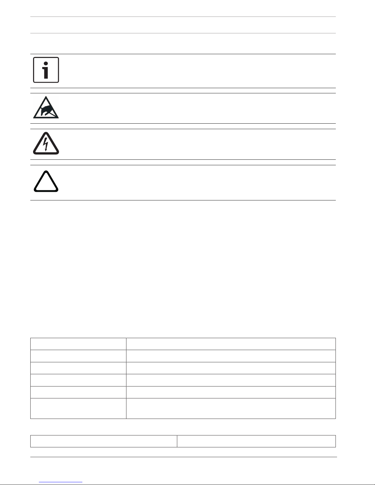
Hinweis!
Die Installation darf nur von autorisiertem Fachpersonal durchgeführt werden.
Vorsicht!
Elektrostatische Entladung (ESD)! Elektronische Bauteile können beschädigt werden.
Erdungsarmband anlegen oder andere geeignete Maßnahmen ergreifen.
Gefahr!
Stromführende Bauteile und abisolierte Kabel!
Verletzungsgefahr durch Stromschlag. Bei Anschlussarbeiten muss die Anlage stromlos sein.
!
Vorsicht!
Systemfunktion nicht garantiert! Fällt die Spannung unter den unteren Grenzwert von
20,4VDC, können angeschlossene Signalgeber ohne Störungsmeldung an der Zentrale
ausfallen. Aus diesem Grund muss die externe Stromversorgung extern überwacht werden.
2 Funktionsbeschreibung
FLM-420-NAC Signalgeber-Koppler ermöglichen die Verbindung von akustischen Signalgebern,
Blitzleuchten und Sirenen an LSN-Brandmelderzentralen. Ein Koppler stellt jeweils eine
überwachte Primärleitung zur Verfügung. Die Ansteuerung der Signalgeberlinie (NAC =
Notification Appliance Circuit) erfolgt durch Umpolung.
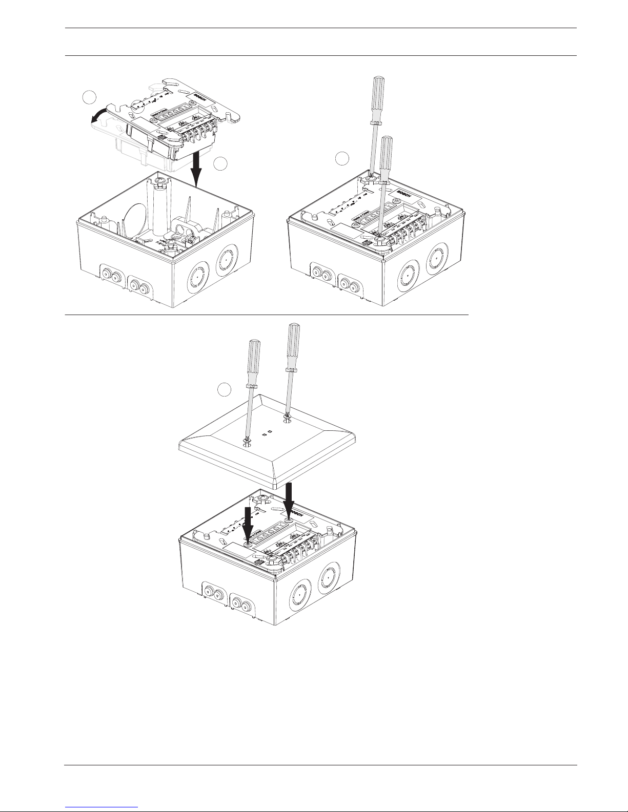
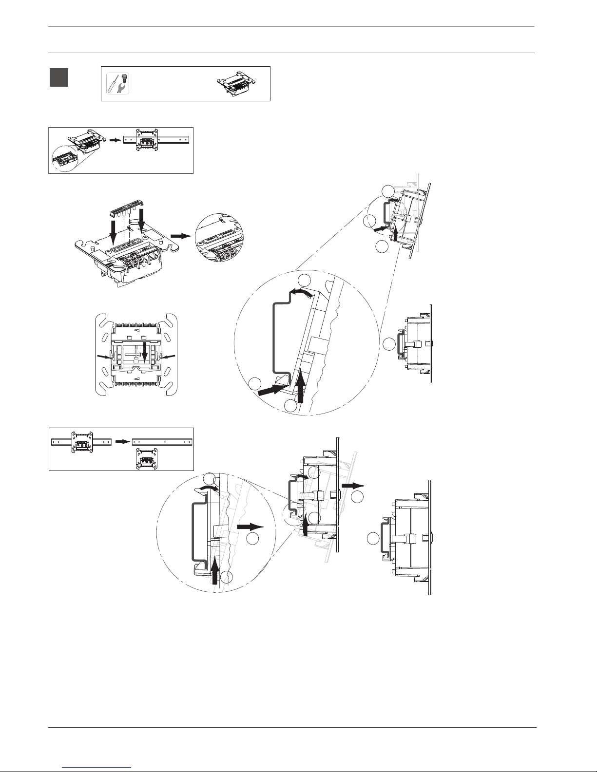
FLM-420-NAC-S dient zur Aufputzmontage mit Gehäuse (siehe Abbildung 1). Der FLM-420NAC-D wird auf einer DIN-Schiene gemäß EN 500022 mit beiliegendem Adapter installiert
(siehe Abbildung 2).
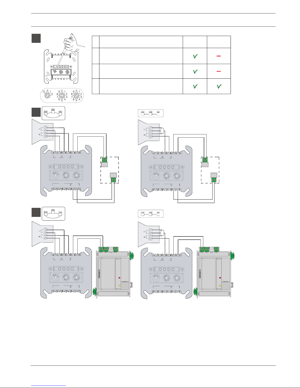
Bringen Sie die Drehschalter für die Adresseinstellung in die gewünschte Position (siehe
Abbildung 3).
3 Anschluss
Beachten Sie bei der Verwendung von BCM-0000-B als externe Stromversorgung die
Abbildung 4. Beachten Sie bei Versorgung durch LSN 0300/LSN 1500 die Abbildung 5. Die
Zusatzspannung wird von LSN 0300/LSN 1500 überwacht.
Beschreibung Funktion
IN: b | a NAC-Zone Eingang
OUT: b | a NAC-Zone Ausgang
0 V | 24 V Ext. Stromversorgung
LSN: a1- | b1+ | a2- | b2+ LSN kommend | LSN gehend
FAIL ac | FAIL bat Störungseingang für Ausfall der Netzstromversorgung | Störungseingang für
Batterieausfall
4 Technische Daten
Anzeigeelemente 2 LEDs (rot = Alarm, grün = Normalbetrieb)

Signaling Devices Interface Module Technische Daten | de 11
Bosch Sicherheitssysteme GmbH Installation Guide 2018.02 | 7 | F.01U.003.284
Eingangsspannung 15VDC bis 33VDC
Max. Stromaufnahme aus LSN 6,06mA (Normalbetrieb und Alarm)
Max. Stromaufnahme aus externer Stromversorgung 15mA (Normalbetrieb) + Ausgangsstrom
Externe Stromversorgung 20,4VDC bis 29VDC
Max. Ausgangsstrom 3A (im Alarmfall, aus ext. Stromversorgung)
EOL-Widerstand 3,9kΩ
Schutzklasse nach IEC60950 Einrichtung der SchutzklasseIII
Schutzart nach IEC60529 FLM-420-NAC-S: IP 54
FLM-420-NAC-D: IP 30
Betriebstemperatur/Lagertemperatur -20°C bis 50°C / -25°C bis 85°C
Relative Feuchte < 96%, nicht kondensierend
Material Kopplergehäuse PPE (Noryl)
Material Aufputzgehäuse ABS/PC-Blend
Hinweis!
Elektrische Daten für den integrierten Kurzschluss-Isolator gemäß EN 54-17:2005 finden Sie in
der Installationsanleitung F.01U.003.287 für FLM-I-420-S.

12 en | Safety Signaling Devices Interface Module
2018.02 | 7 | F.01U.003.284 Installation Guide Bosch Sicherheitssysteme GmbH
1 Safety
Notice!
Installation must only be carried out by authorized specialist personnel.
Caution!
Electrostatic discharge (ESD)! Electronic components could become damaged. Ground
yourself using a wrist strap or take other suitable actions.
Danger!
Live components and stripped cable!
Risk of injury from electric shock. The system must be current-free during connection work.
!
Caution!
System function not guaranteed! If the voltage falls under the lower limit of 20.4 V DC, then
connected notification appliances can fail without fault message on the panel. Therefore, the
external power supply has to be monitored with external means.
2 Functional description
FLM-420-NAC Signaling Device Interface Modules make it possible to connect sounder,
strobes, and horns to LSN fire panels. Each interface offers one monitored primary line. The
control of the signaling device line (NAC=Notification Appliance Circuit) is performed through
polarity reversal.
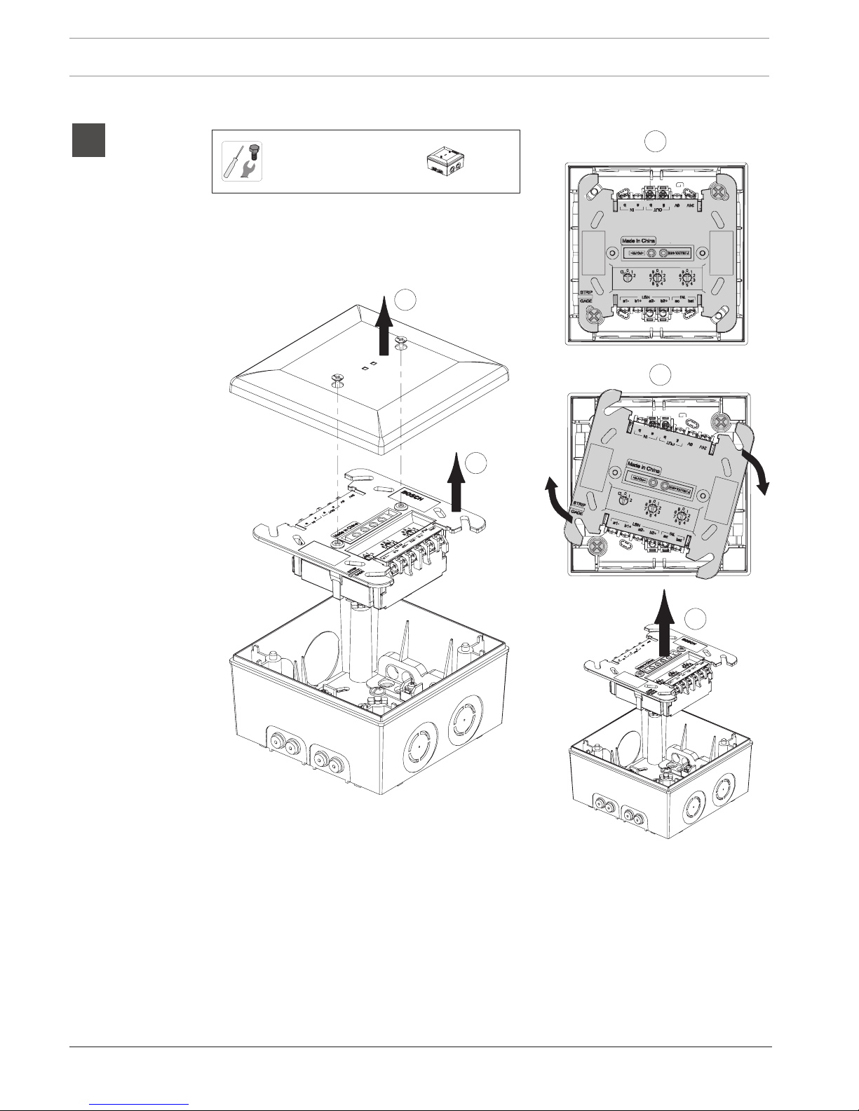
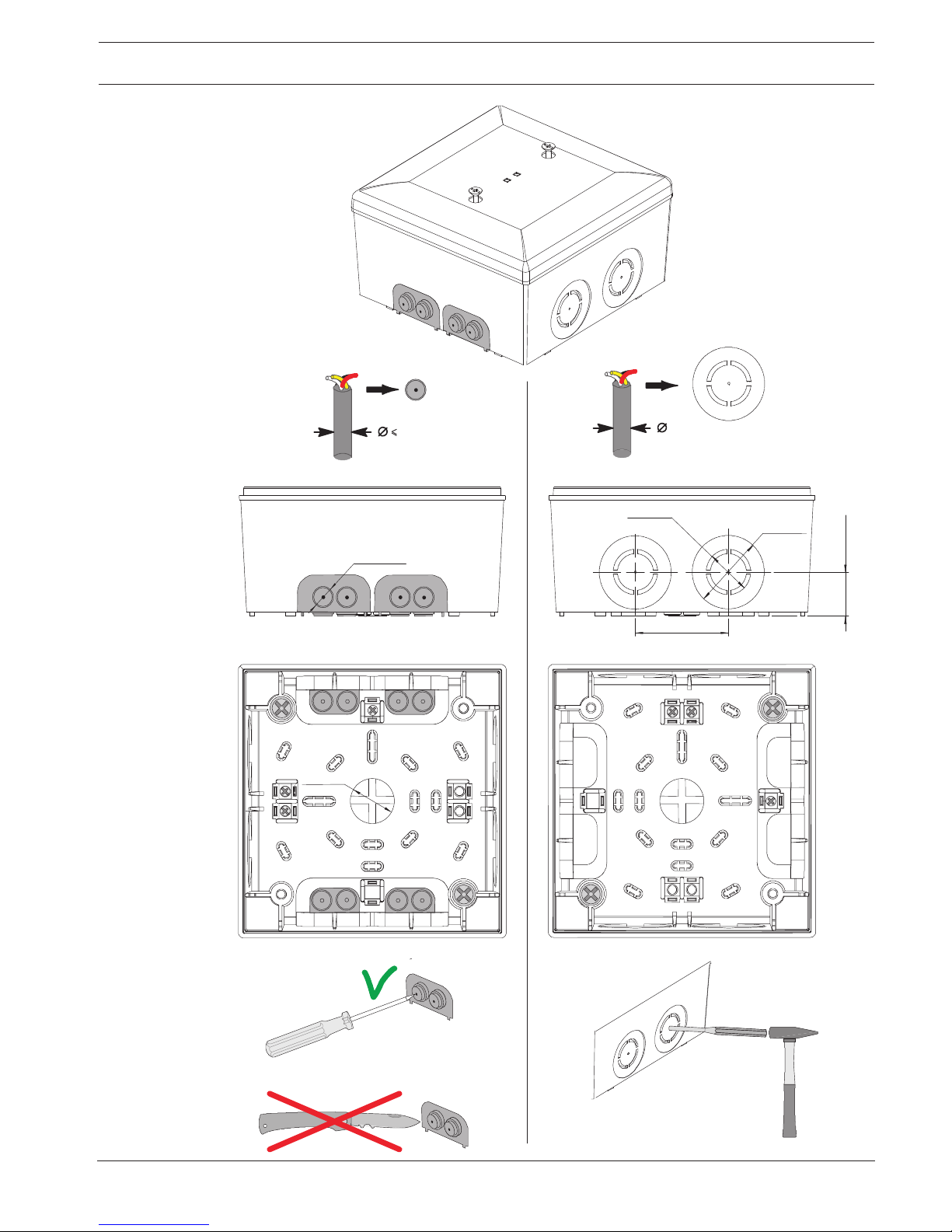
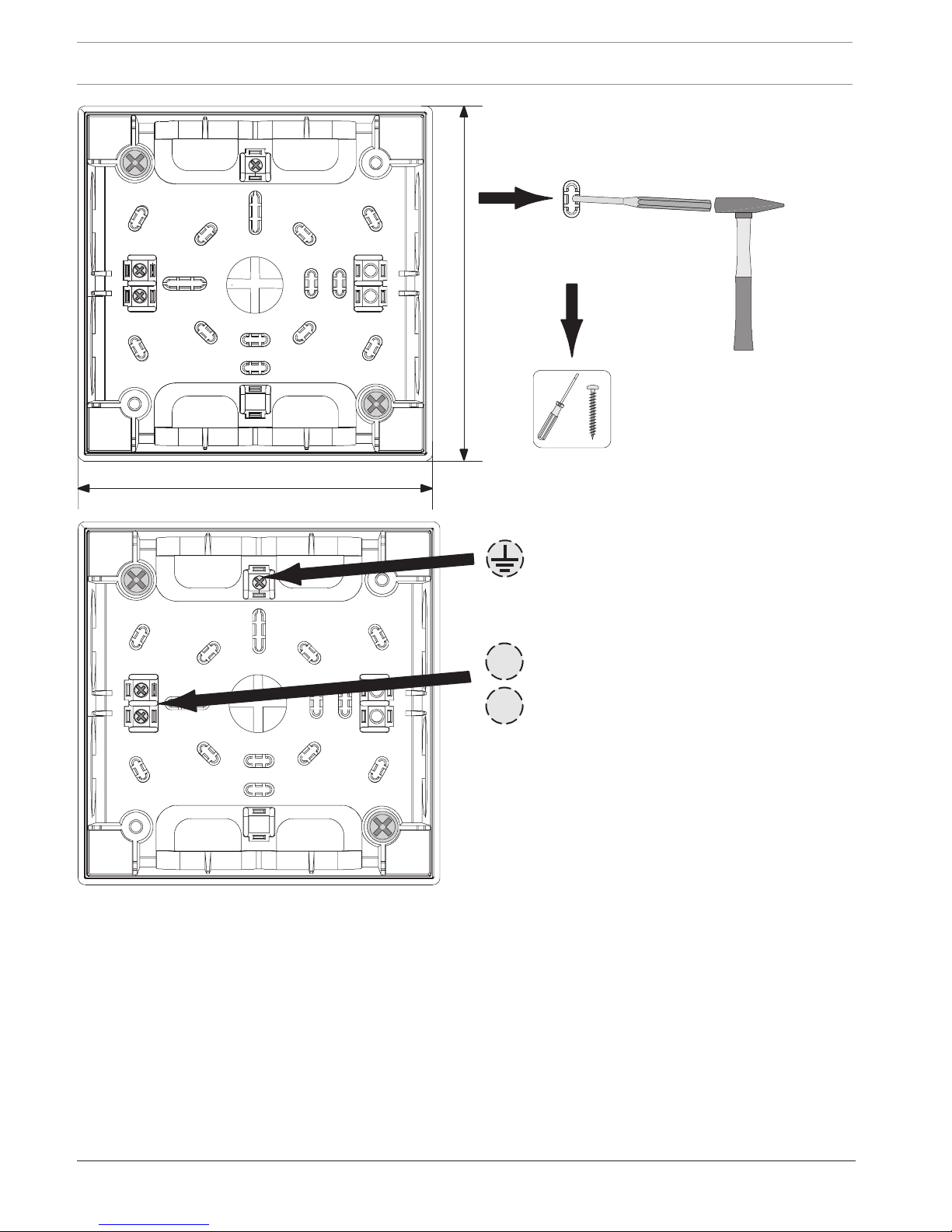
FLM-420-NAC-S is for surface-mounting, with housing, see graphic 1 . FLM-420-NAC-D is
installed on a DIN rail in accordance with EN 500022 with enclosed adapter, see graphic 2.
For address setting, fit the rotary switches in the required position, see graphic 3.
3 Connection
When using BCM-0000-B as external power supply, see graphic 4. When supplied by LSN
0300/LSN 1500, see graphic 5, auxiliary power is monitored by LSN 0300/LSN 1500.
Description Function
IN: b | a NAC zone input
OUT: b | a NAC zone output
0 V | 24 V Ext. power supply
LSN: a1- | b1+ | a2- | b2+ LSN in | LSN out
FAIL ac | FAIL bat Fault input for mains power failure | Fault input for battery failure
4 Technical specifications
Display elements 2 LEDs (red = alarm, green = normal operation)
Input voltage 15V DC to 33V DC
Max. current consumption from LSN 6.06mA (normal operation and alarm)

Signaling Devices Interface Module Technical specifications | en 13
Bosch Sicherheitssysteme GmbH Installation Guide 2018.02 | 7 | F.01U.003.284
Max. current consumption from external power
supply
15mA (normal operation) + output current
External power supply 20.4 V DC to 29V DC
Max. output current 3A (during an alarm, from ext. power supply)
EOL resistance 3.9kΩ
Classes of equipment as per IEC60950 Class III equipment
Protection class as per IEC60529 FLM-420-NAC-S: IP 54
FLM-420-NAC-D: IP 30
Operating temperature / Storage temperature -20°C to 50°C / -25°C to 85°C
Relative humidity < 96%, non-condensing
Material interface module housing PPO (Noryl)
Material surface-mount housing ABS + PC-Blend
Notice!
Electrical data for the built-in short circuit isolator according to EN 54-17:2005, you find in
F.01U.003.287 FLM-I 420-S Installation Guide.

14 es | Seguridad Signaling Devices Interface Module
2018.02 | 7 | F.01U.003.284 Installation Guide Bosch Sicherheitssysteme GmbH
1 Seguridad
Aviso!
La instalación debe realizarla exclusivamente personal autorizado y especializado.
Precaución!
Descarga electroestática (ESD). Los componentes electrónicos podrían resultar dañados.
Conecte su cuerpo a tierra mediante un brazalete o tome otras medidas adecuadas.
Peligro!
Componentes conductores y cable pelado.
Riesgo de lesiones por descarga eléctrica. El sistema debe estar sin corriente eléctrica
durante los trabajos de conexión.
!
Precaución!
No se garantizada el funcionamiento del sistema. Si la tensión se encuentra por debajo del
límite inferior de 20,4V CC, los dispositivos de notificación conectados pueden fallar aunque
no aparezcan mensajes de fallo en el panel. Por lo tanto, la fuente de alimentación externa se
debe controlar con medios externos.
2 Descripción funcional
FLM-420-NAC Los módulos interfaz para dispositivos de señalización permiten conectar
sirenas, luces estroboscópicas y bocinas convencionales a las centrales de incendios LSN.
Cada módulo proporciona una línea primaria supervisada. El control de la línea de dispositivos
de señalización (NAC = Circuitos de Dispositivos de Notificación) se realiza mediante inversión
de polaridad.
FLM-420-NAC-Sse monta en superficie, con carcasa; consulte el gráfico 1 . FLM-420-NAC-D
está instalado en un raíl DIN según la EN 500022 con el adaptador incluido; consulte el gráfico
2.
Para configurar la dirección, coloque los conmutadores giratorios en la posición necesaria.
Consulte el gráfico 3.
3 Conexión
Al usar BCM-0000-B como fuente de alimentación externa, consulte el gráfico 4. Al utilizar el
suministro de LSN 0300/LSN 1500 (consulte el gráfico 5), LSN 0300/LSN 1500 monitoriza la
alimentación auxiliar.
Descripción Función
IN: b | a Entrada de zona NAC
OUT: b | a Salida de zona NAC
0 V | 24 V Fuente de alimentación ext.
LSN: a1- | b1+ | a2- | b2+ Entrada LSN | salida LSN
FAIL ac | FAIL bat Entrada de avería para fallo de alimentación principal | Entrada de avería para
fallo de batería

Signaling Devices Interface Module Especificaciones técnicas | es 15
Bosch Sicherheitssysteme GmbH Installation Guide 2018.02 | 7 | F.01U.003.284
4 Especificaciones técnicas
Elementos indicadores 2 LED (rojo = alarma, verde = funcionamiento normal)
Tensión de entrada De 15V CC a 33V CC
Consumo de corriente máximo de LSN 6,06mA (funcionamiento normal y alarma)
Consumo de corriente máximo de la fuente de
alimentación externa
15 mA (funcionamiento normal) + corriente de salida
Fuente de alimentación externa De 20,4 V CC a 29V CC
Corriente de salida máx. 3 A (durante una alarma de fuente de alimentación ext.)
Resistencia RFL 3,9kΩ
Clases de equipo según IEC60950 Equipo de clase III
Clase de protección según IEC60529 FLM-420-NAC-S: IP 54
FLM-420-NAC-D: IP 30
Temperatura de almacenamiento/funcionamiento
permitida
De -20°C a 50°C/de -25°C a 85°C
Humedad relativa < 96% (sin condensación)
Material de la carcasa del módulo interfaz PPO (Noryl)
Material de la carcasa de montaje en superficie Mezcla ABS + PC
Aviso!
Puede consultar los datos eléctricos para el aislador de cortocircuito integrados según la
norma EN 54-17:2005 en F.01U.003.287 Guía de instalación de FLM-I S-420.

16 fr | Sécurité Signaling Devices Interface Module
2018.02 | 7 | F.01U.003.284 Installation Guide Bosch Sicherheitssysteme GmbH
1 Sécurité
Remarque!
L'installation doit être réalisée uniquement par un employé spécialisé et habilité.
Attention!
Risque de décharge électrostatique Les composants électroniques peuvent être
endommagés. Reliez-vous à la terre à l'aide d'un bracelet anti-statique ou protégez-vous par
tout autre moyen adéquat.
Danger!
Composants sous tension et câbles dénudés.
Risque de blessures par choc électrique. Assurez-vous que l'alimentation électrique est
coupée lorsque vous effectuez les branchements de l'appareil.
!
Attention!
Fonction système non garantie! Si la tension tombe en dessous de la limite inférieure de 20,4
Vcc, les dispositifs de notification connectés peuvent tomber en panne sans qu'aucun
message de défaillance ne s'affiche sur la centrale. Par conséquent, le bloc d'alimentation
externe doit être surveillé à l'aide de moyens externes.
2 Description fonctionnelle
FLM-420-NAC Les modules d'interface de dispositifs de signalisation permettent de connecter
des sirènes, flashs et avertisseurs sonores aux centrales incendie LSN. Chaque interface
présente une ligne principale surveillée Le contrôle de la ligne du dispositif de signalisation
NAC (NAC) est effectué par inversion de la polarité.
Le FLM-420-NAC-S est destiné à un montage en surface, avec un boîtier. Voir le graphique 1 .
Le FLM-420-NAC-D est installé sur un rail DIN conformément à la norme EN 500022 avec
l'adaptateur fourni (voir la figure 2).
Pour le paramétrage de l'adressage, placez les commutateurs rotatifs sur la position requise
(voir la figure 3).
3 Connexion
Lors de l'utilisation du BCM-0000-B en tant que bloc d'alimentation externe, consultez le
graphique 4. S'il est fourni par LSN 0300/LSN 1500, consultez le graphique 5, l'alimentation
auxiliaire est contrôlée par LSN 0300/LSN 1500.
Description Fonction
IN: b | a Entrée zone NAC
OUT: b | a Sortie zone NAC
0 V | 24 V Bloc d'alimentation ext.
LSN: a1- | b1+ | a2- | b2+ Entrée LSN | Sortie LSN
FAIL ac | FAIL bat Entrée défaillance pour coupure alimentation secteur | Entrée défaillance
pour défaillance batterie

Signaling Devices Interface Module Caractéristiques techniques | fr 17
Bosch Sicherheitssysteme GmbH Installation Guide 2018.02 | 7 | F.01U.003.284
4 Caractéristiques techniques
Éléments d'affichage 2 Voyants LED (rouge= alarme, vert= fonctionnement
normal)
Tension d'entrée 15Vcc à 33Vcc
Consommation de courant max. de LSN 6,06mA (fonctionnement normal et alarme)
Consommation maximale de l'alimentation externe 15mA (fonctionnement normal) + courant de sortie
Alimentation externe 20,4 Vcc à 29Vcc
Courant de sortie max. 3A (pendant une alarme, d'alimentation ext.)
Résistance de fin de ligne 3,9kΩ
Catégories d'équipement selon CEI60950 Équipement de catégorieIII
Catégorie de protection suivant CEI60529 FLM-420-NAC-S: IP 54
FLM-420-NAC-D: IP 30
Température de fonctionnement / Température de
stockage
-20°C à 50°C / -25°C à 85°C
Humidité relative < 96%, sans condensation
Matière du boîtier du module d'interface PPO (Noryl)
Matière du boîtier pour montage en surface ABS + PC-Blend
Remarque!
Caractéristiques électriques pour le sectionneur intégré conformément à la norme EN
54-17:2005, qui figure dans le guide d'installation F.01U.003.287 FLM-I 420-S.

18 it | Sicurezza Signaling Devices Interface Module
2018.02 | 7 | F.01U.003.284 Installation Guide Bosch Sicherheitssysteme GmbH
1 Sicurezza
Avviso!
L'installazione deve essere eseguita solo da personale specializzato autorizzato.
Attenzione!
Scariche elettrostatiche (ESD). Rischio di danneggiamento per i componenti elettronici.
Eseguire un collegamento a terra mediante un cinturino o prendere le dovute precauzioni.
Pericolo!
Componenti in tensione e cavi scoperti.
Rischio di scosse elettriche. Il sistema non deve essere collegato alla presa di corrente
durante le operazioni di collegamento.
!
Attenzione!
L'operatività del sistema non è garantita. Se la tensione scende sotto il limite inferiore di 20,4
V CC, i dispositivi di segnalazione collegati possono restituire un errore senza visualizzare un
messaggio di errore sulla centrale. Pertanto, l'alimentazione esterna deve essere monitorata
con dispositivi esterni.
2 Descrizione delle funzioni
I moduli di interfaccia dei dispositivi di segnalazione FLM-420-NAC consentono di collegare
sirene, lampeggianti stroboscopici e segnalatori acustici alle centrali di rivelazione incendio
LSN. Ogni interfaccia garantisce il controllo di una linea primaria. Il controllo della linea del
dispositivo di segnalazione (NAC = Notification Appliance Circuit) viene eseguito tramite
inversione di polarità.
Il dispositivo FLM-420-NAC-S è per montaggio su superficie con alloggiamento, vedere la figura
1. Il dispositivo FLM-420-NAC-D è installato su un binario DIN in conformità alla normativa EN
500022 con adattatore incluso, vedere la figura 2.
Per l'impostazione degli indirizzi, adattare i rotary switch nella posizione desiderata, vedere la
figura 3.
3 Collegamento
Se si utilizza BCM-0000-B come alimentatore esterno, vedere la figura 4. Se fornito da LSN
0300/LSN 1500, vedere la figura 5, l'alimentazione ausiliaria è monitorata da LSN 0300/LSN
1500.
Descrizione Funzione
IN: b | a Ingresso zona NAC
OUT: b | a Uscita zona NAC
0 V | 24 V Alimentazione est.
LSN: a1- | b1+ | a2- | b2+ Ingresso LSN | Uscita LSN
FAIL ac | FAIL bat Guasto ingresso per interruzione alimentazione di rete | Guasto uscita per
guasto della batteria

Signaling Devices Interface Module Specifiche tecniche | it 19
Bosch Sicherheitssysteme GmbH Installation Guide 2018.02 | 7 | F.01U.003.284
4 Specifiche tecniche
Elementi del display 2 LED (rosso = allarme, verde = funzionamento normale)
Tensione di ingresso Da 15V CC a 33V CC
Consumo di corrente max da LSN 6,06mA (funzionamento normale ed allarme)
Consumo massimo di corrente da alimentazione
esterna
15mA (funzionamento normale) + corrente di uscita
Alimentatore esterno Da 20,4 V CC a 29V CC
Corrente di uscita max 3A (durante un allarme, da alimentazione esterna)
Resistenza EOL 3,9kΩ
Classi di apparecchiature conformi a IEC60950 Apparecchiatura di classe III
Classe di protezione conforme a IEC60529 FLM-420-NAC-S: IP 54
FLM-420-NAC-D: IP 30
Temperatura di stoccaggio, temperatura operativa Da -20°C a 50°C/da -25°C a 85°C
Umidità relativa < 96% senza condensa
Materiale alloggiamento modulo interfaccia PPO (Noryl)
Materiale alloggiamento per montaggio su superficie Composto ABS + PC
Avviso!
Dati elettrici per il dispositivo di isolamento per cortocircuiti integrato in conformità alla
normativa EN 54-17:2005, presente nella Guida all'installazione di F.01U.003.287 FLM-I 420-S.

20 nl | Veiligheid Signaling Devices Interface Module
2018.02 | 7 | F.01U.003.284 Installation Guide Bosch Sicherheitssysteme GmbH
1 Veiligheid
Bericht!
De installatie mag uitsluitend worden uitgevoerd door bevoegd en daartoe opgeleid
gespecialiseerd personeel.
Voorzichtig!
Elektrostatische ontlading (ESD)! Elektronische onderdelen kunnen beschadigd raken. Bereid
uzelf goed voor en draag een polsband of neem andere passende maatregelen.
Gevaar!
Spanningvoerende onderdelen en gestripte kabel!
Gevaar voor letsel door elektrische schok. Het systeem moet spanningsloos zijn tijdens het
aansluiten.
!
Voorzichtig!
Systeemfunctie niet gegarandeerd! Als de spanning onder de onderste limiet van 20,4 VDC
komt, kunnen verbonden signaleringsapparaten uitvallen zonder storingsmelding op de
centrale. Daarom moet de externe voeding met externe middelen worden bewaakt.
2 Functies
Met behulp van FLM-420-NAC interfacemodules voor signaalgevers kunnen akoestische
signaalgevers, flitslichten en hoorns worden aangesloten op LSN-brandmeldcentrales. De
interface heeft één bewaakte primaire lijn. De bediening van de signaalgeverlijn
(NAC=Notification Appliance Circuit) vindt plaats via ompoling.
FLM-420-NAC-S is bestemd voor opbouwmontage, met behuizing, zie afbeelding 1 . FLM-420NAC-D is geïnstalleerd op een DIN-rail volgens EN 500022 met bijgevoegde adapter, zie
afbeelding 2.
Voor de adresinstelling zet u de draaischakelaars in de vereiste positie, zie afbeelding 3.
3 Aansluiting
Bij gebruik van BCM-0000-B als externe voeding, zie afbeelding 4. Indien geleverd door LSN
0300/LSN 1500, zie afbeelding 5, wordt de hulpvoeding bewaakt door LSN 0300/LSN 1500.
Omschrijving Functie
IN: b | a Ingang NAC-zone
OUT: b | a Uitgang NAC-zone
0 V | 24 V Ext. voeding
LSN: a1- | b1+ | a2- | b2+ LSN in | LSN uit
FAIL ac | FAIL bat Storingsingang voor netvoedingsstoring | Storingsingang voor accustoring
4 Technische specificaties
Display-elementen 2 LED's (rood = alarm, groen = normale werking)
Ingangsspanning 15VDC tot 33VDC
Max. stroomverbruik van LSN 6,06mA (normale werking en alarm)

Signaling Devices Interface Module Technische specificaties | nl 21
Bosch Sicherheitssysteme GmbH Installation Guide 2018.02 | 7 | F.01U.003.284
Max. stroomverbruik vanuit externe voeding 15mA (normale werking) + uitgangsstroom
Externe voeding 20,4 VDC tot 29VDC
Max. uitgangsstroom 3A (tijdens een alarm, vanuit ext. voeding)
Afsluitweerstand 3,9kΩ
Veiligheidsklasse conform IEC 60950 Klasse III-apparatuur
Beschermingsklasse conform IEC 60529 FLM-420-NAC-S: IP 54
FLM-420-NAC-D: IP 30
Bedrijfstemperatuur / Opslagtemperatuur -20°C tot 50°C / -25°C tot 85°C
Relatieve vochtigheid < 96%, niet-condenserend
Materiaal van de behuizing van de interfacemodule PPO (Noryl)
Materiaal van de opbouwbehuizing Kunststofcomposiet van ABS en PC
Bericht!
Elektrische gegevens voor de ingebouwde kortsluitisolator conform EN 54-17: 2005 vindt u in
de F.01U.003.287 FLM-I 420-S Installatiehandleiding.

22 pl | Bezpieczeństwo Signaling Devices Interface Module
2018.02 | 7 | F.01U.003.284 Installation Guide Bosch Sicherheitssysteme GmbH
1 Bezpieczeństwo
Uwaga!
Instalacja może być wykonywana wyłącznie przez wyspecjalizowany personel, posiadający
stosowne upoważnienie.
Przestroga!
Wyładowania elektrostatyczne! Ryzyko uszkodzenia elementów elektronicznych. Założyć
opaskę uziemiającą lub podjąć inne odpowiednie środki ostrożności.
Niebezpieczeństwo!
Elementy pod napięciem i kable bez izolacji!
Ryzyko porażenia prądem elektrycznym. Na czas prac instalacyjnych system należy odłączyć
od zasilania.
!
Przestroga!
Działanie systemu nie jest gwarantowane! Jeśli napięcie spadnie poniżej dolnej wartości
granicznej wynoszącej 20,4VDC, podłączone sygnalizatory mogą przestać działać bez
przesłania komunikatu o usterce do centrali. Z tego powodu zasilanie zewnętrzne musi być
monitorowane przy użyciu urządzeń zewnętrznych.
2 Opis działania
Moduły interfejsu urządzeń sygnalizacyjnych FLM-420-NAC umożliwiają podłączenie
sygnalizatora akustycznego, sygnalizatorów optycznych oraz syren do central sygnalizacji
pożaru typu LSN. Każdy interfejs zapewnia dostęp do jednej monitorowanej linii podstawowej.
Sterowanie linią urządzenia sygnalizacyjnego (NAC, ang. „Notification Appliance Circuit”;
obwód sygnalizatora) jest realizowane przez odwrócenie polaryzacji.
Moduł FLM-420-NAC-S jest przeznaczony do montażu natynkowego i wyposażony w obudowę,
patrz grafika 1. Moduł FLM-420-NAC-D jest montowany na szynie DIN w sposób zgodny z
normą EN 500022 wraz z dołączonym adapterem, patrz grafika 2.
W celu ustawienia adresu należy obrócić przełączniki obrotowe do żądanej pozycji, patrz
grafika 3.
3 Połączenie
Jeżeli moduł BCM-0000-B jest używany jako zasilacz zewnętrzny, zobacz rys. 4. Jeżeli jest on
zasilany przez moduł LSN 0300/LSN 1500, zobacz rys. 5; dodatkowe zasilanie jest
monitorowane przez moduł LSN 0300/LSN 1500.
Opis Funkcja
IN: b | a Wejście strefy NAC
OUT: b | a Wyjście strefy NAC
0 V | 24 V Zewnętrzne zasilanie
LSN: a1- | b1+ | a2- | b2+ Wejście LSN | wyjście LSN
FAIL ac | FAIL bat Wejście usterki zasilacza | Wejście usterki akumulatora

Signaling Devices Interface Module Parametry techniczne | pl 23
Bosch Sicherheitssysteme GmbH Installation Guide 2018.02 | 7 | F.01U.003.284
4 Parametry techniczne
Wskaźniki 2 diody LED (czerwona = alarm, zielona = normalne
działanie)
Napięcie wejściowe Od 15VDC do 33VDC
Maks. pobór prądu z sieci LSN 6,06mA (normalne działanie i alarm)
Maks. pobór prądu z zewnętrznego źródła zasilania 15mA (normalne działanie) + prąd wyjściowy
Zasilanie zewnętrzne Od 20,4VDC do 29VDC
Maks. prąd wyjściowy 3A (w trakcie alarmu, z zewnętrznego źródła zasilania)
Rezystancja końca linii 3,9kΩ
Klasa urządzeń zgodnie z normą IEC60950 Urządzenie klasy III
Stopień ochrony zgodnie z normą IEC60529 FLM-420-NAC-S: IP 54
FLM-420-NAC-D: IP 30
Temperatura pracy / temperatura przechowywania Od -20°C do 50°C / od -25°C do 85°C
Wilgotność względna < 96%, bez kondensacji
Materiał obudowy modułu interfejsu Tworzywo PPO (Noryl)
Materiał obudowy puszki montażowej ABS + PC-Blend
Uwaga!
Dane elektryczne dotyczące wbudowanych izolatorów zwarć zgodnych z normą EN
54-17:2005 można znaleźć w dokumencie F.01U.003.287 Instrukcja instalacji FLM-I 420-S.

24 pt | Segurança Signaling Devices Interface Module
2018.02 | 7 | F.01U.003.284 Installation Guide Bosch Sicherheitssysteme GmbH
1 Segurança
Aviso!
A instalação só pode ser executada por pessoal autorizado e especializado.
Cuidado!
Descargas eletrostáticas (ESD)! Os componentes eletrónicos poderão ficar danificados. Use
uma pulseira antiestática ou tome outras medidas adequadas.
Perigo!
Componentes com corrente e cabo descarnado!
Risco de lesões devido a choque elétrico. O sistema não pode ter alimentação elétrica
durante os trabalhos de ligação.
!
Cuidado!
Função do sistema não garantida! Se a tensão descer abaixo do limite inferior de 20,4 V CC,
os equipamentos de notificação ligados podem falhar sem ser apresentada uma mensagem
de falha no painel. Assim, a fonte de alimentação externa tem de ser monitorizada através de
meios externos.
2 Descrição funcional
FLM-420-NAC Os Módulos de interface para avisadores acústicos permitem ligar equipamento
de notificação sonora, strobes e sirenes aos painéis de incêndio LSN. Cada interface
disponibiliza uma linha convencional monitorizada. O controlo da linha do avisador acústico
(NAC = equipamento de notificação) é efetuado através da inversão da polaridade.
O FLM-420-NAC-S destina-se a montagem saliente, sem caixa; consulte o gráfico 1. O
FLM-420-NAC-D é instalado numa calha DIN de acordo com a norma EN 500022 e com
adaptador incluído; consulte o gráfico 2.
Para efetuar a definição de endereço, coloque os interruptores rotativos na posição
pretendida: consulte o gráfico 3.
3 Ligação
Quando utilizar o BCM-0000-B como fonte de alimentação externa, consulte o gráfico 4.
Quando fornecido pelo LSN 0300/LSN 1500, consulte o gráfico 5; a alimentação auxiliar é
monitorizada pelo LSN 0300/LSN 1500.
Descrição Função
IN: b | a Entrada de zona NAC
OUT: b | a Saída de zona NAC
0 V | 24 V Fonte de alimentação externa
LSN: a1- | b1+ | a2- | b2+ LSN entrada | LSN saída
FAIL ac | FAIL bat Entrada de falha para falha na rede elétrica | Entrada de falha para falha da
bateria

Signaling Devices Interface Module Dados técnicos | pt 25
Bosch Sicherheitssysteme GmbH Installation Guide 2018.02 | 7 | F.01U.003.284
4 Dados técnicos
Elementos de visualização 2 LEDs (vermelho = alarme, verde = funcionamento
normal)
Tensão de entrada 15V CC a 33V CC
Consumo máx. de corrente LSN 6,06mA (funcionamento normal e alarme)
Consumo máx. de corrente da fonte de alimentação
externa
15mA (funcionamento normal) + corrente de saída
Fonte de alimentação externa 20,4 V CC a 29V CC
Corrente de saída máx. 3A (durante um alarme, da fonte de alimentação ext.)
Resistência fim-de-linha 3,9kΩ
Classes de equipamento em conformidade com a
norma IEC60950
Equipamento de classe III
Classe de proteção em conformidade com a norma
IEC60529
FLM-420-NAC-S: IP 54
FLM-420-NAC-D: IP 30
Temperatura de serviço/Temperatura de
armazenamento
-20 °C a 50 °C/-25 °C a 85 °C
Humidade relativa < 96%, sem condensação
Material da caixa do módulo interface PPO (Noryl)
Material da caixa para montagem saliente ABS + PC-Blend
Aviso!
É possível encontrar os dados elétricos do isolador de curto-circuito integrado de acordo com
a EN 54-17:2005 no Manual de instalação F.01U.003.287 FLM-I 420-S.

26 ro | Siguranţă Signaling Devices Interface Module
2018.02 | 7 | F.01U.003.284 Installation Guide Bosch Sicherheitssysteme GmbH
1 Siguranţă
Notificare!
Instalarea trebuie realizată numai de către personal autorizat de specialitate.
Atenție!
Descărcare electrostatică (ESD)! Componentele electronice se pot defecta. Utilizaţi un cablu
de punere la pământ sau luaţi alte măsuri corespunzătoare.
Pericol!
Componente sub tensiune şi cablu neizolat!
Pericol de electrocutare. Sistemul nu trebuie să fie alimentat cu curent electric în timpul
instalării.
!
Atenție!
Funcţionarea sistemului nu este garantată! Dacă tensiunea scade sub limita inferioară de 20,4
V c.c., aparatele de notificare conectate pot funcţiona necorespunzător fără ca un mesaj de
eroare să fie afişat pe panou. În consecinţă, sursa de alimentare externă trebuie monitorizată
prin mijloace externe.
2 Descriere funcţională
Modulele de interfaţă pentru dispozitiv de semnalizare FLM-420-NAC fac posibilă conectarea
semnalizatorului acustic, stroboscoapelor şi sirenelor la panourile de incendiu LSN. Fiecare
interfaţă oferă o linie principală monitorizată. Comanda liniei dispozitivului de semnalizare
(NAC= Circuit dispozitiv de notificare) este efectuată prin inversarea polarităţii.
FLM-420-NAC-S este conceput pentru montare la suprafaţă, cu carcasă, consultaţi imaginea 1.
FLM-420-NAC-D se instalează pe o şină DIN, în conformitate cu EN 500022 cu adaptor inclus,
consultaţi imaginea 2.
Pentru setarea adresei, dispuneţi întrerupătoarele rotative în poziţia necesară, consultaţi
imaginea 3.
3 Conexiune
Atunci când se utilizează BCM-0000-B ca sursă de alimentare externă, consultați graficul 4.
Atunci când alimentarea este asigurată de LSN 0300/LSN 1500, consultați graficul 5,
alimentarea auxiliară este monitorizată de LSN 0300/LSN 1500.
Descriere Funcție
IN: b | a Intrare zonă NAC
OUT: b | a Ieșire zonă NAC
0 V | 24 V Sursă de alimentare ext.
LSN: a1- | b1+ | a2- | b2+ Intrare LSN | Ieșire LSN
FAIL ac | FAIL bat Intrare eroare pentru întrerupere alimentare de la rețea | Intrare eroare
pentru întrerupere alimentare de la baterie

Signaling Devices Interface Module Specificaţii tehnice | ro 27
Bosch Sicherheitssysteme GmbH Installation Guide 2018.02 | 7 | F.01U.003.284
4 Specificaţii tehnice
Elemente de afişare 2 LED-uri (roşu = alarmă, verde = funcţionare normală)
Tensiune de intrare 15V c.c. - 33V c.c.
Consum electric max. de la LSN 6,06 mA (funcţionare normală şi alarmă)
Consum electric max. de la sursă de alimentare
externă
15 mA (funcţionare normală) + curent de ieşire
Sursa de alimentare externă 20,4 V c.c. - 29V c.c.
Curent de ieşire max. 3 A (în timpul unei alarme, de la sursă de alimentare ext.)
Rezistenţă EOL 3,9kΩ
Clase de echipament cf. IEC60950 Clasa III de echipament
Clasă de protecţie cf. IEC60529 FLM-420-NAC-S: IP 54
FLM-420-NAC-D: IP 30
Temperatură de funcţionare/Temperatură de
depozitare
-20 °C până la 50 °C/-25 °C până la 85 °C
Umiditate relativă < 96%, fără condens
Material carcasă modul de interfaţă PPO (Noryl)
Material carcasă cu montare pe suprafaţă Amestec ABS + PC
Notificare!
Specificaţiile electrice privind izolatorul de scurtcircuit încorporat, în conformitate cu EN
54-17:2005, se găsesc în Ghidul de instalare F.01U.003.287 FLM-I 420-S.

28 ru | Безопасность Signaling Devices Interface Module
2018.02 | 7 | F.01U.003.284 Installation Guide Bosch Sicherheitssysteme GmbH
1 Безопасность
Замечание!
Установка должна выполняться только квалифицированными специалистами.
Внимание!
Электростатический разряд! Возможно повреждение электронных компонентов.
Обязательно заземлите себя контактной манжетой или другим способом.
Опасно!
Оголенные провода и компоненты под напряжением!
Опасность поражения электрическим током! Во время работ по подключению система
должна быть обесточена.
!
Внимание!
Функционирование системы не гарантируется! Если напряжение опускается ниже 20,4 В
постоянного тока (нижнего предела), в работе подключенных устройств оповещения
может произойти сбой, а сообщение о неисправности на панели не отобразится.
Следовательно, необходимо контролировать внешний источник питания с помощью
сторонних устройств.
2 Описание принципа работы
Интерфейсные модули оповещателя FLM-420-NAC позволяют подключать к пожарным
панелям LSN звуковые оповещатели, импульсные лампы и сирены. Каждый интерфейс
позволяет подключить одну контролируемую цепь. Контроль цепи оповещения (NAC=цепь
устройств оповещения) осуществляется посредством изменения полярности.
FLM-420-NAC-S предназначен для поверхностного монтажа без корпуса, см. рис. 1.
FLM-420-NAC-D устанавливается на DIN рейку с использованием поставляемого в
комплекте адаптера в соответствии со стандартом EN 500022, см. рис. 2.
Для настройки адреса установите поворотные переключатели в нужное положение: см.
рисунок 3.
3 Подключение
Если BCM-0000-B используется в качестве внешнего источника питания, см. рис. 4. Если
питание обеспечивается модулем LSN 0300/LSN 1500, см. рис. 5, дополнительное питание
контролируется LSN 0300/LSN 1500.
Описание Назначение
IN: b | a Зона NAC, вход
OUT: b | a Зона NAC, выход
0 V | 24 V Внешний источник питания
LSN: a1- | b1+ | a2- | b2+ Вход LSN | Выход LSN
FAIL ac | FAIL bat Вход сбоя питания от сети | Вход сбоя аккумулятора

Signaling Devices Interface Module Технические характеристики | ru 29
Bosch Sicherheitssysteme GmbH Installation Guide 2018.02 | 7 | F.01U.003.284
4 Технические характеристики
Элементы индикации Светодиоды 2 (красный = тревога, зеленый =
нормальная работа)
Входное напряжение 15–33В постоянного тока
Макс. потребление тока от шлейфа LSN 6,06 мА (норма и тревога)
Макс. ток потребления от внешнего источника
питания
15мА (норма) + ток на выходе
Внешнее питание 20,4–29В постоянного тока
Макс. ток на выходе 3А (во время тревоги, от внешнего источника питания)
Сопротивление EOL 3,9кОм
Классы оборудования по IEC 60950 Класс оборудования III
Класс защиты по IEC60529 FLM-420-NAC-S: IP 54
FLM-420-NAC-D: IP 30
Рабочая температура / Температура хранения -20–50°C / -25–85°C
Относительная влажность < 96%, без конденсации
Материал корпуса интерфейсного модуля PPO (норил)
Материал корпуса для установки на поверхности ABS + PC-смесь
Замечание!
Электрические характеристики встроенного изолятора для защиты от короткого
замыкания в соответствии с EN54-17 можно найти в руководстве по установке
F.01U.003.287 FLM-I 420-S.

30 tr | Güvenlik Signaling Devices Interface Module
2018.02 | 7 | F.01U.003.284 Installation Guide Bosch Sicherheitssysteme GmbH
1 Güvenlik
Uyarı!
Montaj yalnızca yetkili uzman personel tarafından gerçekleştirilmelidir.
Dikkat!
Elektrostatik deşarj (ESD)! Elektronik bileşenler hasar görebilir. Kendinizi bilek bandıyla
topraklayın veya başka uygun önlemler alın.
Tehlike!
Elektrik yüklü parçalar ve çıplak kablo!
Elektrik çarpması sonucu yaralanma tehlikesi. Bağlantı işlemleri yapılırken sistemde akım
olmamalıdır.
!
Dikkat!
Sistemin çalışacağı garanti edilemez! Gerilim 20,4 V DC'lik alt sınırın altına düşerse bağlı uyarı
cihazları panelde hata mesajı verilmeden çalışmayabilir. Bu nedenle, harici güç kaynağının
harici araçlarla izlenmesi gerekir.
2 İşlev açıklaması
FLM-420-NAC Sinyalleme Cihazı Arayüz Modülleri LSN FACP'lerine sesli uyarı cihazı, flaşör ve
korna bağlanmasına olanak sağlar. Her arayüz bir adet izlenen birincil hat sağlar. Sinyalleme
cihazı hattının kontrolü (NAC=Uyarı Cihazı Devresi) kutup değişimiyle gerçekleştirilir.
FLM-420-NAC-S muhafaza ile yüzeye montaj içindir, grafik 1'e bakın. FLM-420-NAC-D bir DIN
rayı üzerine birlikte verilen adaptörle EN 500022'ye uygun olarak monte edilir, bkz. grafik 2.
Adres ayarı için, döner düğmeleri gerekli konuma takın, bkz. grafik 3.
3 Bağlantı
BCM-0000-B'yi harici güç kaynağı olarak kullanırken grafik 4'e bakın. LSN 0300/LSN 1500 ile
beslendiğinde, grafik 5'e bakın, yardımcı güç LSN 0300/LSN 1500 tarafından izlenir.
Açıklama İşlev
IN: b | a NAC bölge girişi
OUT: b | a NAC bölge çıkışı
0 V | 24 V Harici güç kaynağı
LSN: a1- | b1+ | a2- | b2+ LSN girişi | LSN çıkışı
FAIL ac | FAIL bat Şebeke güç kesintisi için hata girişi | Batarya arızası hata girişi
4 Teknik özellikler
Ekran elemanları 2 LED (kırmızı = alarm, yeşil = normal çalışma)
Giriş gerilimi 15V DC - 33V DC
LSN'den maksimum akım tüketimi 6,06mA (normal çalışma ve alarm)
Harici güç kaynağından maks. akım tüketimi 15mA (normal çalışma) + çıkış akımı

Signaling Devices Interface Module Teknik özellikler | tr 31
Bosch Sicherheitssysteme GmbH Installation Guide 2018.02 | 7 | F.01U.003.284
Harici güç kaynağı 20,4 V DC - 29V DC
Maks. çıkış akımı 3A (alarm sırasında, harici güç kaynağından)
EOL direnci 3,9kΩ
IEC60950 uyarınca ekipman sınıfları III. sınıf ekipman
IEC60529 uyarınca koruma sınıfı FLM-420-NAC-S: IP 54
FLM-420-NAC-D: IP 30
Çalışma sıcaklığı/Saklama sıcaklığı -20°C - 50°C/-25°C - 85°C
Bağıl nem %< 96, yoğuşmasız
Arayüz modülü muhafaza malzemesi PPO (Noryl)
Yüzeye montaj muhafaza malzemesi ABS + PC Karışımı
Uyarı!
F.01U.003.287 FLM-420-S Kurulum Kılavuzu'nda bulabileceğiniz EN 54-17:2005'e göre dahili
kısa devre yalıtıcısının elektriksel verileri.

Bosch Sicherheitssysteme GmbH
Robert-Bosch-Ring 5
85630 Grasbrunn
Germany
www.boschsecurity.com
© Bosch Sicherheitssysteme GmbH, 2018
 Loading...