

Bosch FLM-420-01, FLM-420-01-D Installation Manual
Output‑input Interface Module
FLM‑420‑01I1‑D
Installation Guide
de deutsch
en english
es español
fr français
it italiano
nl nederlands
pl polski
pt português
ro român
ru русский
tr türkçe


Output-input Interface Module | 3
de deutsch Sicherheitshinweise 8
en english
es español
fr français
it italiano
nl nederlands
pl polski
pt português
ro român
ru русский
tr türkçe
Safety Notes 10
Seguridad 12
Sécurité 15
Sicurezza 18
Veiligheid 21
Bezpieczeństwo 23
Segurança 25
Siguranţă 28
Безопасность 30
Güvenlik 33
Bosch Sicherheitssysteme GmbH Installation Guide 2019.02 | 4.0 | F.01U.032.854

4 All | Graphics Output-input Interface Module
110 mm
110 mm
48 mm
40 mm
1
3
2
1
4
2
3
1
4
I.
II.
III.
2
3
1
2
1
3
2
Graphics
2019.02 | 4.0 | F.01U.032.854 Installation Guide Bosch Sicherheitssysteme GmbH
Output-input Interface Module Graphics | All 5
Xxx xXx xxX
Xxx xXx xxX
Xxx xXx xxX
A = 0 0 0
A = CL 0 0
A = 0 0 1 - 2 5 4
3
1.
2.
R
EOL
R
EOL
RΣ = R
L/2
+ R
L/2
+ R
EOL
R
L/2
R
L/2
R
L/2
R
L/2
IN
IN
4
A Xxx xXx xxX LSN improved BZ 500 LSN
UEZ 2000 LSN
UGM 2020
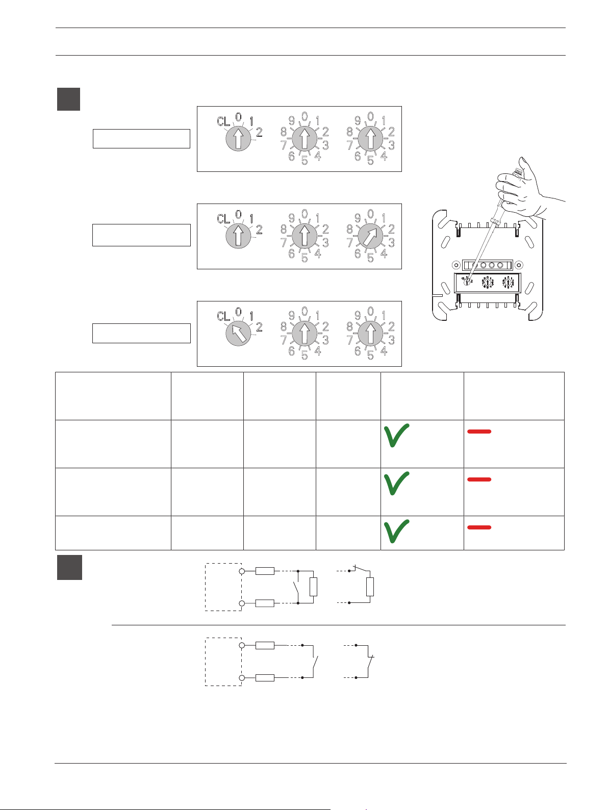
0 0 0
Automatic addressing
Automat. Adressierung
0 0 1 - 2 5 4
Manual addressing
Manuelle Adressierung
CL 0 0 CL 0 0
0 0 0
0 / 1 / 2 0 - 9 0 - 9
Bosch Sicherheitssysteme GmbH Installation Guide 2019.02 | 4.0 | F.01U.032.854
6 All | Graphics Output-input Interface Module
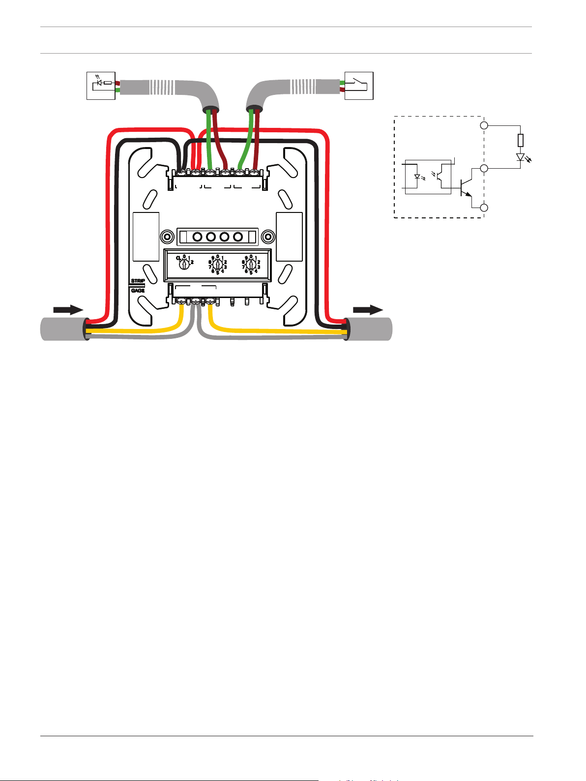
LSN
OUT IN
LSN
LSN
POWER IN
POW+ POW-
OUT
POW+ OUT-
IN
IN+ IN-
b1+ b2+a-
OUT-
POW-
OUT
POW+
max. 3 mmax. 3 m
2019.02 | 4.0 | F.01U.032.854 Installation Guide Bosch Sicherheitssysteme GmbH
Output-input Interface Module Graphics | All 7
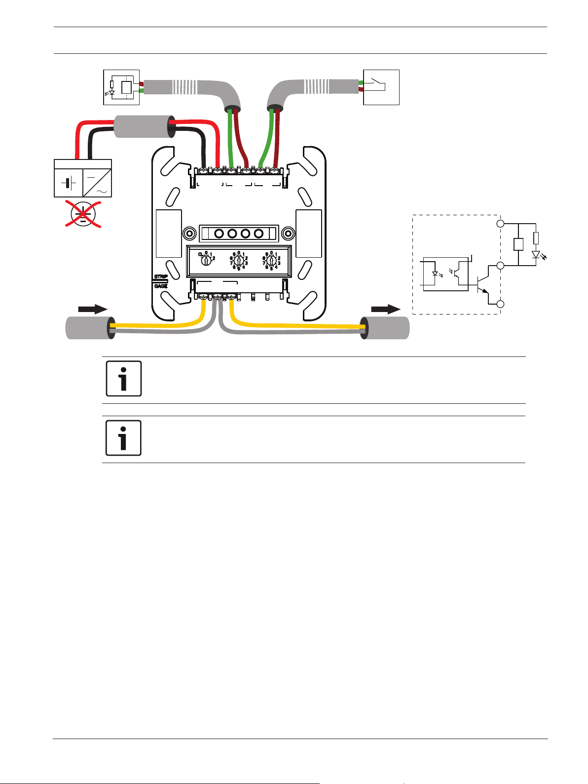
5 - 30 V DC
+U 0V
LSN LSN
LSN
POWER IN
POW+ POW-
OUT
POW+ OUT-
IN
IN+ IN-
b1+ b2+a-
OUT IN
max. 3 mmax. 3 m
100
OUT-
POW-
OUT
POW+
100
Notice!
When using an external power supply you have to add a 100 Ω resistor between POW+ and
OUT-.
Hinweis!
Bei Gebrauch einer externen Stromversorgung müssen Sie einen 100 Ω Widerstand zwischen
POW+ und OUT- einfügen.
Bosch Sicherheitssysteme GmbH Installation Guide 2019.02 | 4.0 | F.01U.032.854
8 de | Sicherheitshinweise Output-input Interface Module
1 Sicherheitshinweise
Hinweis!
Die Installation darf nur von autorisiertem Fachpersonal durchgeführt werden.
Vorsicht!
Elektrostatische Entladung (ESD)! Elektronische Bauteile können beschädigt werden.
Erdungsarmband anlegen oder andere geeignete Maßnahmen ergreifen.
2 Funktionsbeschreibung
Der Koppler hat einen Halbleiterausgang für die Steuerung externer Geräte und einen
überwachten Eingang.
Der Ausgang ist vom LSN-Ring galvanisch getrennt und kurzschlussfest. Angeschlossene
Verbraucher können von der Zusatzspannungsversorgung der Brandmelderzentrale mit
Spannung versorgt werden.
Für den Eingang können zwei Überwachungsfunktionen ausgewählt werden (siehe
Abbildungen):
1. Überwachung einer Linie mit EOL-Widerstand auf Ruhe oder Auslösung (Unterbrechung/
Kurzschluss)
2. Überwachung eines potentialfreien Kontakts auf die Zustände „offen“ oder „geschlossen“
Die Programmierung erfolgt über die Programmiersoftware der Brandmelderzentrale.
Informationen zum Installieren und Entfernen des FLM-420-O1I1-D auf bzw. von einer DINSchiene nach EN 60715 mit beiliegendem Adapter finden Sie auf Abbildung 2. Alternativ kann
der Koppler in das Aufputzgehäuse FLM-IFB126-S eingebaut werden.
3 Anschaltung
Der Ausgang OUT/OUT- wird gegen das Minuspotential des Kopplers geschaltet (POWER IN/
POW-).
Das Pluspotential für OUT/POW+ wird von der Zusatzspannungsversorgung (AUX) der
Brandmelderzentrale geliefert.
OUT/POW+ und POWER IN/POW+ sind intern verbunden.
Alternativ kann das Pluspotential für OUT/POW+ von einem externen Netzteil geliefert werden
(siehe Abbildung 4). Das externe Netzteil muss erdpotentialfrei sein.
Hinweis!
Die maximale Leitungslänge pro Eingang und Ausgang beträgt 3m.
Die maximale Leitungslänge aller im Ring oder Stich angeschlossenen Eingänge beträgt
insgesamt 500m.
Dabei müssen auch die Ausgänge berücksichtigt werden, die vom LSN nicht galvanisch
getrennt sind, z.B. an C-Punkte angeschlossene Peripheriegeräte.
Die Ansteuerung des Eingangs IN muss vom LSN galvanisch getrennt erfolgen (z.B. über
Relaiskontakte, Druckknopf etc.).
Für den Eingang gilt eine Mindestansteuerzeit von 3,2s.
Beschreibung Funktion
IN IN+ | IN- Eingang
OUT POW+ Bezugspotential (+)
2019.02 | 4.0 | F.01U.032.854 Installation Guide Bosch Sicherheitssysteme GmbH

Output-input Interface Module Technische Daten | de 9
Beschreibung Funktion
OUT- Ausgang (geschaltetes Minuspotential)
POWER IN POW+ | POW- Spannungsversorgung Ausgang (OUT)
LSN b1+ | a- | b2+ LSN (kommend/gehend)
4 Technische Daten
Eingangsspannung LSN 15 – 33VDC
Max. Stromaufnahme aus LSN 1,9mA
Stromaufnahme bei angesteuertem Ausgang ≤ 2,5mA
Ausgang
– Max. Schaltspannung der Ausgänge 30VDC
– Max. schaltbarer Ausgangsstrom 700mA pro Ausgang (abhängig von der Stromversorgung)
– Externe Stromversorgung 5 – 30VDC
Eingang
Linienüberwachung mit EOL:
– EOL-Widerstand nominell 3,9 kΩ
– Gesamtwiderstand RΣ (RΣ=R
L/2
+R
L/2
+R
) – In Ruhe: 1500 – 6000Ω
EOL
– Kurzschluss: < 800Ω
– Unterbrechung: > 12000Ω
Kontaktüberwachung
– Max. Stromstärke (Strompuls) 8mA
Mindestansteuerzeit des Eingangs 3,2s
Max. Leitungslänge Eingang/Ausgang 3m
Max. Leitungslänge für alle Ein‑ und Ausgänge, die an
500m gesamt
die Ringleitung oder den Stich angeschlossen und
nicht galvanisch vom LSN getrennt sind
Zul. Drahtquerschnitt 0,6 – 3,3mm
2
Zul. Betriebstemperatur -20 – +65°C
Zul. Lagertemperatur -25 – +80°C
Zul. relative Feuchte < 96%, nicht kondensierend
Schutzart nach IEC 60529 IP 54
Schutzklasse nach IEC 60950 Einrichtung der Schutzklasse III
Gehäusematerial und ‑farbe PPE (Noryl), Grauweiß (ähnlich RAL 9002)
Abmessungen mit Adapter (BxHxT) Ca. 110x110x48mm
Gewicht Ca. 95g
Bosch Sicherheitssysteme GmbH Installation Guide 2019.02 | 4.0 | F.01U.032.854
10 en | Safety Notes Output-input Interface Module
1 Safety Notes
Notice!
Installation must only be carried out by authorized specialist personnel.
Caution!
Electrostatic discharge (ESD)! Electronic components could become damaged. Ground
yourself using a wrist strap or take other suitable actions.
2 Functional description
The Interface Module has one semiconductor output for controlling external devices and one
monitored input.
The output is electrically isolated from the LSN loop and protected against short circuits.
Connected loads can be power-supplied by the auxiliary power supply from the fire panel.
For the input, two monitoring functions can be selected (see Graphics):
1. Monitoring a line with EOL resistor for standby or triggering (interruption/short circuit)
2. Monitoring a potential free contact for open and closed states
The programming is carried out via the programming software of the fire panel.
For installing and removal of the FLM-420-O1I1-D on a DIN rail in accordance with EN 60715
with enclosed adapter see figure 2. Optionally, the interface module may be built into the
surface mounted housing FLM-IFB126-S.
3 Connection
The output OUT/OUT- is switched against the negative potential of the interface module
(POWER IN/POW-).
The positive potential for OUT/POW+ is provided by the auxiliary power supply (AUX) from the
fire panel.
OUT/POW+ and POWER IN/POW+ are linked internally.
Alternatively, the positive potential for OUT/POW+ may be provided by an external power
supply unit (see figure 4). The external power supply unit must be free-of-ground.
Notice!
A maximum cable length of 3m is permitted per input and output.
The maximum cable length of all inputs connected to the loop or stub is 500m in total.
Additionally, all outputs which are not electrically isolated from LSN must be included in the
total line length calculation (e.g. peripherals connected via C points).
The activation of the input IN has to be carried out electrically isolated from LSN (e.g. with
relay contacts, pushbutton, etc.).
The input must have a minimum activation time of 3.2s.
Description Function
IN IN+ | IN- Input
OUT POW+ Reference potential (+)
OUT- Output (switched negative potential)
POWER IN POW+ | POW- Power supply output (OUT)
LSN b1+ | a- | b2+ LSN (incoming/outgoing)
2019.02 | 4.0 | F.01U.032.854 Installation Guide Bosch Sicherheitssysteme GmbH

Output-input Interface Module Technical specifications | en 11
4 Technical specifications
LSN input voltage 15 to 33VDC
Max. current consumption from LSN 1.9mA
Current consumption when output activated ≤ 2.5mA
Output
– Max. switched voltage of outputs 30VDC
– Max. output current rating 700mA per output (depending on power supply)
– External power supply 5 to 30VDC
Input
Line monitoring with EOL:
– EOL resistor Nominal 3.9kΩ
– Overall line resistance RΣ (RΣ=R
L/2
+R
L/2
+R
) – In standby: 1500 to 6000Ω
EOL
– Short-circuit: < 800Ω
– Interruption: > 12000Ω
Contact monitoring
– Max. current strength (current pulse) 8mA
Minimum activation time of the input 3.2s
Max. cable length input/output 3m
Maximum cable length of all inputs and outputs
500m in total
which are connected to the loop or stub and not
electrically isolated from LSN
Permissible wire diameter 0.6 to 3.3mm
2
Permissible operating temperature -20 to +65°C
Permissible storage temperature -25 to +80°C
Permissible rel. humidity < 96%, non-condensing
Protection class as per IEC 60529 IP 54
Classes of equipment as per IEC 60950 Class III equipment
Housing material and color PPO (Noryl), gray white (similar to RAL 9002)
Dimensions with adapter (W x H x D) Approx. 110 x 110 x 48 mm
Weight Approx. 95g
Bosch Sicherheitssysteme GmbH Installation Guide 2019.02 | 4.0 | F.01U.032.854
 Loading...