

Page 1
Fire Alarm Systems | F220 Photoelectric Smoke Detectors
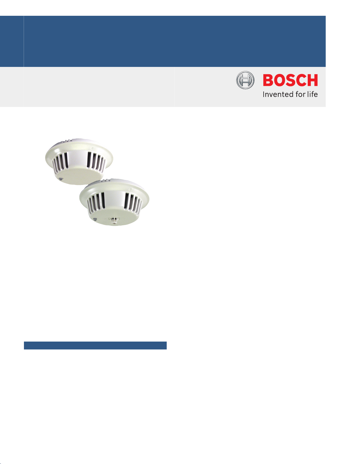
F220 Photoelectric Smoke Detectors
www.boschsecurity.com
u Two-wire or four-wire bases
u 30 ft (9 m) maximum spacing between detectors
u Optional CO-sensor, heat-sensor enhanced
detection chamber
The F220 Photoelectric Smoke Detectors are UL
Listed, open-area photoelectric smoke detectors. Use
them with commercial fire protective signaling
systems and household fire warning systems (see
NFPA 72, the National Fire Alarm Code). These smoke
detectors scatter light using a pulsed infrared source
operating with a gated, high-speed, photodiode
infrared sensor. The symmetry of the optical chamber
allows 360° uniform smoke entry, but minimizes
external light entry. The detectors use low current
electronic circuitry, so they can connect to 12 VDC
nominal or 24 VDC nominal power source circuits.
Functions
Compatible Bases
Configure the detectors into two-wire or four-wire
versions by selecting the appropriate mounting base.
These detectors are compatible with any of the
F220‑B6 bases:
• F220-B6 12/24 VDC Two‑wire Mounting Base
• F220-B6R Standard 12/24 VDC Four‑wire Mounting
Base
• F220-B6RS 24 VDC Four‑wire Mounting Base with
Sounder
• F220-B6C 12/24 VDC Four‑wire Mounting Base with
Auxiliary Relay
u Clean chamber without removal or disassembly
u CleanMe signaling capability
• F220-B6E 12/24 VDC Four‑wire Power Supervision
Mounting Base
• F220-B6PM 24 VDC Four‑wire Addressable Master
Base
• F220-B6PS 12/24 VDC Four‑wire Addressable Base
Monitoring the Detection Chamber
These detectors have several features that work
together to maximize the performance of the optical
chamber:
• Compensation: The detector monitors the chamber
for the effects of dust build-up within the chamber
and automatically compensates for these effects. If
the chamber becomes contaminated beyond its
ability to compensate, the green LED flashes every
4 sec to indicate trouble.
• Chamber Check Self-diagnostics: The detector
automatically indicates visually if the calibration is out
of the factory-listed range. This meets NFPA
guidelines for sensitivity testing, because you can
visually inspect the detector and check the flash rate
of the LED. If the calibration is out of range, the green
LED on the detector flashes once every 4 sec. This
indicates that the detector must be cleaned following
the instructions provided with the detector.
Page 2
2 | F220 Photoelectric Smoke Detectors
• CleanMe Mode: Indicates if the calibration is out of
the factory-listed range by sending a trouble signal to
the CleanMe-compatible control panel, if so
programmed.
• Chambermaid: The detector has a unique cleaning
mechanism. Use the valve on the back of the detector
to insert the nozzle of a can of clean, dry compressed
air. Clean the chamber with a short (1 to 2 sec) blast
of air.
Heat and Carbon Monoxide Enhancements
The detectors are available with an optional fixedtemperature heat sensor, a carbon monoxide (CO)
sensor, or a combination of heat and CO sensors.
These optional sensors enhance the operation of the
smoke detector by reducing false alarms.
• Carbon Monoxide: Without the presence of CO, a
normal byproduct of combustion, the detection
chamber is half as sensitive to smoke as a standard
commercial photoelectric smoke chamber. This
reduces false alarms. When the sensor detects CO,
the detection chamber's sensitivity to smoke
increases so it equals or exceeds that of a standard
commercial photoelectric smoke chamber.
Notice
The F220-PTHC detects carbon monoxide (CO) as
a component of a fire. It is not a CO detector and
cannot activate an alarm in the presence of CO
only.
• Heat: When the heat sensor detects a temperature
rise, the photoelectric chamber becomes more smoke
sensitive. The heat sensor initiates an alarm if the
ambient temperature exceeds +135°F (+57°C).
Dual-color LED
A dual-color LED indicator flashes green every 8 sec
when the detector has power and the smoke sampling
circuitry is working. If CleanMe is enabled, the green
LED double flashes (two flashes a half second apart)
every 8 sec to indicate normal operation. The LED
turns red if an alarm is sent. After the alarm condition
clears, reset the detector by interrupting its power. If
the chamber becomes contaminated beyond its ability
to compensate, the green LED flashes every 4 sec to
indicate trouble.
Test Functions
The F220 Photoelectric Smoke Detectors feature a
unique magnet operation and sensitivity test function.
Test the detector's operation by placing the magnet
next to the detector's LED for three consecutive
flashes. This causes the detector to send an alarm.
Placing a magnet next to the detector's LED for at
least one red flash but less than three flashes activates
the detector's sensitivity mode.
Tamper Detection
When detector heads are correctly installed in any of
the F220-B6 bases, the positive power line provides
tamper detection. The control panel initiates a trouble
signal if a detector is removed from its base. A
mechanical tamper lock comes with each base to
prevent unauthorized head removal.
Certifications and approvals
Region Certification
Europe CE 89/336/EEC, EN50130-4/A Sept 1998,
USA UL UROX: Smoke-automatic Fire Detectors
FM F220 Smokes
CSFM see our website
NYCMEA
MSFM 2200 Sep 2008
Hong Kong HKFSD (P and PTH only)
EN61000-6-3 Oct 2001
(ANSI/UL 268), UROX7: Smoke-automatic Fire Detectors Certified for Canada (CAN/ULC-S529)
117-05-E
Installation/configuration notes
Compatible Control Panels
Addressable Systems: compatible with addressable
systems controlled by B9512G, B8512G, D9412GV4,
D7412GV4, D9412GV3, D7412GV3, D9412GV2,
D7412GV2, D9412G, or D7412G Control Panels or the
D9124 Fire Alarm Control Panel when used with the
F220-B6PM or F220-B6PS Addressable Detector
Bases.
Two-wire: Bosch Security Systems, Inc. makes no
claim written, oral, or implied that the F220
Photoelectric Smoke Detectors work with any twowire control panels except those specified in the
Control Panel Compatibility chart in the Technical
Service Note (P/N: 4998148185).
Four-wire: compatible with all UL Listed four-wire
control panels. Refer to the control panel's installation
instructions for proper end-of-line (EOL) resistor
selection.
Mounting the Bases
Notice
Consult NFPA‑72 for proper detector placement.
Depending on local regulations, the bases can be
surface mounted directly on four-inch square or
octagonal electrical boxes and single-gang switch
boxes.
Notice
The volume of any electrical box used should be
large enough to accommodate the number and
size of conductors as specified by the National
Electrical Code or any local authorities having
jurisdiction (AHJ).
Page 3

3 | F220 Photoelectric Smoke Detectors
Loop Supervision
Loop supervision requires one D275 or F220-B6E per
loop when using F220‑B6R/B6C bases and is
supervised by the control panel.
Wiring the Bases
Refer to the F220 Series Detectors with
F220‑B6/C/E/R Bases Installation Instructions (P/
N: 4998138694), the F220 Series Detectors with
F220‑B6RS Bases Installation Instructions (P/
N: F01U029847), or the F220-B6PS/M Installation
Instructions (P/N: 4998149982) for detailed wiring
instructions.
Parts included
Quan
tity
1 Detector with dust cover
Component
Technical specifications
Environmental
Relative Humidity: 0% to 95% non-condensing;
15% to 95% non-condensing for CO
sensing model
Temperature (normal
operating):
+32°F to +100°F (0°C to +38°C)
Mechanical
Color: White
Dimensions
(diameter x H):
6.75 in. x 2.25 in. (17.1 cm x 6.4 cm)
Electrical
Current (alarm):
(detector head only)
Current (start‑up/
standby):
Maximum RMS Ripple: 25% of DC input
Power-up Time: 22 seconds maximum
Voltage (standby)
F220-B6: 8.5 VDC to 32.0 VDC
F220-B6C/-B6R/-B6E: 10.0 VDC to 30.0 VDC
F220-B6RS: 16.0 VDC to 30.0 VDC
20 mA minimum at 8.5 VDC;
35 mA maximum at 32 VDC
0.12 mA maximum at 32 VDC
Ordering information
F220‑PTHC Photoelectric Smoke Detector with +135°F
(+57°C) Heat and Carbon Monoxide Sensors
Photoelectric detector head with heat and CO sensor
augmentation only; requires base.
Order number F220-PTHC
F220‑PTH Photoelectric Smoke Detector with +135°F
(+57°C) Heat Sensor
Photoelectric detector head with heat sensor only;
requires base.
Order number F220-PTH
F220‑P Photoelectric Smoke Detector
Photoelectric detector head only; requires base.
Order number F220-P
Accessories
D275 Power Supervision Module
Line supervision device for four-wire fire detection
circuits
Order number D275
DRA‑5 Remote Annunciator (5 VDC)
Designed to provide remote annunciation of alarms for
a number of Bosch smoke and heat detectors
Order number DRA-5
DT‑2 Detector Removal Tool
Use the DT‑2 to remove, replace, or test the detector
head
Order number DT-2
F220‑B6 12/24 VDC Two‑wire Base
Standard base for two‑wire (12 VDC or 24 VDC
system) applications.
Order number F220-B6
F220‑B6R Standard 12/24 VDC Four‑wire Base
Standard base for four‑wire (12 VDC or 24 VDC)
detector systems.
Order number F220-B6R
F220‑B6RS 24 VDC Four‑wire Detector Base with Sounder
Four-wire detector base with sounder for use with the
F220 Photoelectric Smoke and Heat Detectors.
Order number F220-B6RS
F220‑B6C 12/24 VDC Four‑wire Base with Auxiliary
Form C Relay
Four‑wire base with a normally‑open (NO) alarm loop
relay and a set of auxiliary contacts (Form C).
Order number F220-B6C
F220-B6PM: with D299: 18.9 VDC to 28.0 VDC
without D299: 9.6 VDC to 28.0 VDC
F220- B6PS: 18.9 VDC to 28.0 VDC
Trademarks
All hardware and software product names used in this
document are likely to be registered trademarks and
must be treated accordingly.
F220‑B6E 12/24 VDC Four‑wire Power Supervision Base
with End‑of‑line Power Monitoring Relay
Four‑wire base with a normally‑open (NO) alarm relay
and an EOL power supervision relay.
Order number F220-B6E
Page 4

4 | F220 Photoelectric Smoke Detectors
Represented by:
North America: Europe, Middle East, Africa: Asia-Pacific: China: Latin America and Caribbean:
Bosch Security Systems, Inc.
130 Perinton Parkway
Fairport, New York, 14450, USA
Phone: +1 800 289 0096
Fax: +1 585 223 9180
security.sales@us.bosch.com
www.boschsecurity.us
Bosch Security Systems B.V.
P.O. Box 80002
5617 BA Eindhoven, The Netherlands
Phone: + 31 40 2577 284
Fax: +31 40 2577 330
emea.securitysystems@bosch.com
www.boschsecurity.com
Robert Bosch (SEA) Pte Ltd, Security
Systems
11 Bishan Street 21
Singapore 573943
Phone: +65 6571 2808
Fax: +65 6571 2699
apr.securitysystems@bosch.com
www.boschsecurity.asia
Bosch (Shanghai) Security Systems Ltd.
203 Building, No. 333 Fuquan Road
North IBP
Changning District, Shanghai
200335 China
Phone +86 21 22181111
Fax: +86 21 22182398
www.boschsecurity.com.cn
Robert Bosch Ltda Security Systems Division
Via Anhanguera, Km 98
CEP 13065-900
Campinas, Sao Paulo, Brazil
Phone: +55 19 2103 2860
Fax: +55 19 2103 2862
latam.boschsecurity@bosch.com
www.boschsecurity.com
© Bosch Security Systems 2016 | Data subject to change without notice
2701164683 | en, V9, 04. Mar 2016
F220‑B6PM 24 VDC Four‑wire Addressable Multiple Detector Base
The multiple detector base provides an address on the
FACP data expansion circuit for its detector and up to
an additional 19 detectors. It accepts the F220
Photoelectric Smoke Detector Heads and Heat
Detector Heads.
Order number F220-B6PM
F220‑B6PS 12/24 VDC Four‑wire Addressable Single Detector Base
The single detector base provides an address on the
FACP data expansion circuit for its detector. It accepts
the F220 Photoelectric Smoke Detector Heads and
Heat Detector Heads.
Order number F220-B6PS
 Loading...