

Page 1

EA120B
Installation Instructions
EN
Alert Unit
Page 2

EA120B | Installation Instructions |
4
3
1
2
1
2
EN | 2
1.0 General Information
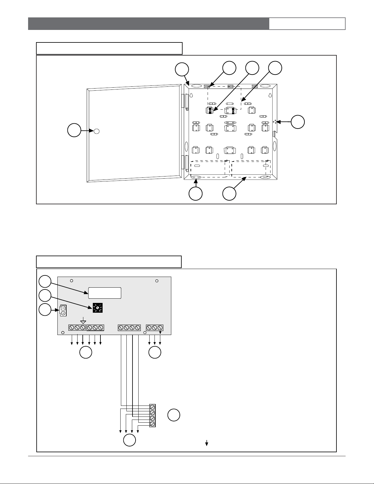
Figure 1: Inside of AE101 Enclosure
The alert unit is a driver for output modules such as a
horn/strobe. The alert unit should be mounted indoors;
however, an outdoor enclosure is available. A horn/
strobe should always be mounted outdoors.
The alert unit receives its main power (for horn/strobe
activation) from the 18 VAC transformer. Backup power
is from a battery. However, the multiplex bus continues
to supply the transponder information on status and
troubles in the event local power is lost.
2.0 Specifications
Table 1: Specifications
Electronics
Enclosures
(H x W x D)
Temperature
Range
Power
Battery
Backup
Outputs
Compatibility
Options
EA120B
Indoor:
AE1 22 cm x 17.7 cm x 4.4 cm
(9 in. x 7 in. x 1.75 in.)
Outdoor:
AE101 37.5 cm x 32.4 cm x 8.9 cm
( 14.75 in. x 12.75 in. x 3.5 in.)
-40°C to +65°C (-40°F to +149°F)
18 VAC, 50 VA
12 VDC Lead Acid Battery
•
Strobe: 500 mA solid state sink,
terminal switches to ground in an
alarm condition.
•
Siren: 500 mA solid state sink,
terminal switches to ground in an
alarm condition.
•
Power: 12 VDC @ 1A, maximum
total for all panel outputs.
EA500B ROM Version 4.00 or higher
•
Batteries: 3 A power (for AE101
Enclosure: E28629B)
•
Battery Cables: C311 (3 A or 7 A
spade lug expansion cables)
•
Tamper Switch: CTS1-70 (for AE1
enclosure)
•
Transformer: TR1850
1 - Outline of where to mount the circuit board.
2 - Use the two plastic screws here.
3 - Insert the two short standoffs into these holes.
Then stick the circuit board inside the enclosure.
4 - Outline of where to place the battery (only 3 Ah
battery fits).
Figure 2: Support Post Assembly
1 - Circuit board
2 - Enclosure
4.0 Wiring
Wire the EA120B Alert Unit (refer to Figure 4).
5.0 Set the Address
3.0 Mounting
Normally, the enclosures are mounted first and all the
wiring is run. Then the electronics are mounted, wired,
and tested.
The enclosures include the necessary electrical and
mechanical mounting hardware.
Mount the circuit board to the enclosure as indicated in
Figure 1, Figure 2, and Figure 3.
Every module on each multiplex bus of the transponder
must have its own address. Set the address on the alert
unit using the address switch (see Figure 4).
Use only address numbers 0 through 7. Do not use
address numbers 8 and 9.
Bosch Security Systems | 6/03 | 33830F
Page 3
EA120B | Installation Instructions |
Figure 3: Inside of AE1 Enclosure
EN | 3
5
1 - Flip-up view to show retainer tabs.
2 - Slide board in between retainer tabs.
3 - Place board over support posts. Secure with two
shorter screws.
4 - Outline of where to mount the circuit board.
1
3
42
6
8 7
5 - Hole for lock and key assembly.
6 - Place tamper switch here. Secure with three larger
screws.
7 - Outline of battery location (1 or 2).
8 - Wire entrances (6).
Figure 4: Wiring the EA120B
1
2
3
BB+
SP1 T P-
0
5
P+ SI- ST- AC AC
4
BUS-
+_+PWR
5
7
BUS BUS +
PWR PWR +
1 - Microprocessor
2 - Address switch
3 - Battery connector (use cable)
4 - SP1 = Switch spare
T = Tamper switch (N/C)
P- = Power (Common)
P+ = Power +
SI- = Switch siren ST- = Switched strobe -
Note: Tamper switch wired to [T] & [P-] terminals
5 - To next device
6 - Transponder
6
7 - Transformer:
AC = Transformer
AC = 18 VAC, 50 VA max
= Earth Ground
Bosch Security Systems | 6/03 | 33830F
Page 4

Bosch Security Systems
130 Perinton Parkway
Fairport, NY 14450-9199 USA
www.boschsecurity.us
Customer Service: (800) 289-0096
Technical Support: (888) 886-6189
© 2003 Bosch Security Systems
Subject to change | Printed in the USA
33830F
 Loading...