

Bosch DX4020-EXP Installation Manual
DX4020-EXP
Installation Guide
Network Interface
EN
Module

DX4020-EXP | Installation Guide | 1. Introduction EN | 2
Trademarks
Microsoft®-and Windows® are either registered
trademarks or trademarks of Microsoft Corporation in
the United States and/or other countries.
Lantronix is a registered trademark of Lantronix
Corporation, registered in the U.S. and other countries.
XPort with its patent-pending technology is a
trademark of Lantronix, Inc.
1. Introduction
The DX4020 is used for bi-directional communications
over Ethernet networks. Typical uses include PC frontend software packages such as PC9000, Remote
Programming Software (RPS) connection for control
panel programming, diagnostic troubleshooting, D6600
Central Station Receiver (CSR) reporting and/or
history retrieval.
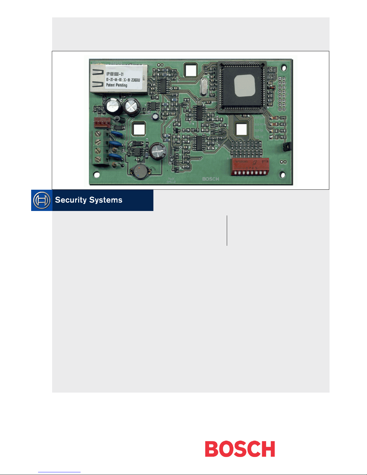
Figure 1: DX4020 Network Interface Module
1
3
1 - Lantronix® Xport™ NIM
2 - EPROM
3 - Data Bus
4 - DIP Switches
5 - Serial/Bus LEDs
6 - P2 Jumper
Failure to follow these instructions can result
in system failure in initiating alarm
conditions. Bosch Security Systems is not
responsible for improperly installed, tested,
or maintained devices.
4 5 6
2
Bosch Security Sys | 8/04 | F01U002192B
Follow these instructions to avoid personal
injury and damage to equipment.
DX4020-EXP | Installation Guide | 2. Overview EN | 3
2. Overview
2.1 Specifications
Table 1: DX4020 Specifications
Dimensions 7.6 cm x 12.7 cm (3 in. x 5 in.)
Current Draw 84 mA max, 80 mA nominal 10 Base-T
110 mA max, 100 mA nominal 100 Base-T
Operation
Voltage
Connectors
Ethernet
Cable
Interface IEEE 802.3
Compatibility
Default IP
Address
12 VDC Nominal
Control
Panel
LAN/WAN RJ-45 Modular Jack
Category 3 or better unshielded twisted
pair
Max Length 100 m (328 ft)
Control Panel Firmware
D9412G, D7412G,
D7212G, D9412, D9112,
D7412, D7212
DS7240V2, DS7220V2 2.xx or later
DS7400xi 4.10 or later
0.0.0.0 (DHCP mode)
Option/Data Bus Terminal
Strip
(Ethernet)
6.3 or later
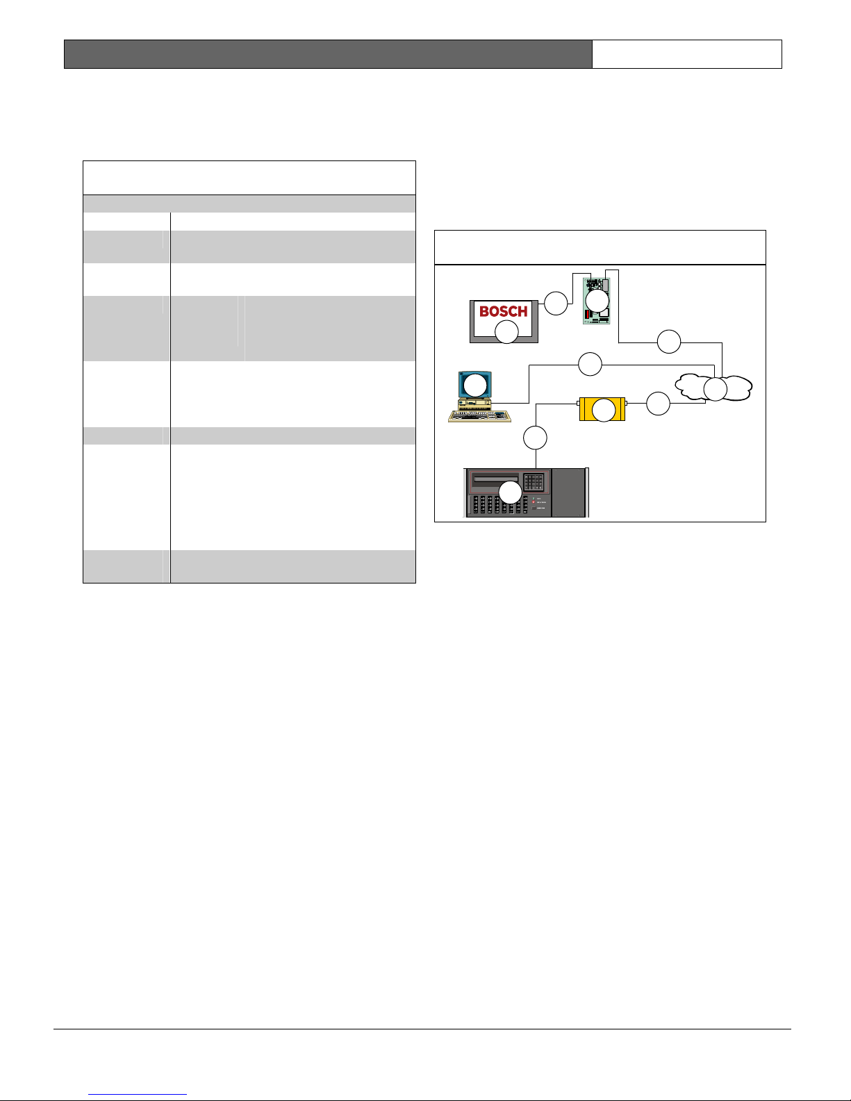
2.2 System Overview
See Figure 2 for a general system connection of the
following devices: a compatible Bosch Security Systems
control panel, a DX4020 Network Interface Module, a
D6600 Receiver, and a D6680 Network Adapter.
Figure 2: System Connections Overview
2
7
1
8
3
5
10
7
6
1 - Compatible Bosch Control Panel
2 - DX4020 Network Interface Module – Ethernet
3 - Host PC running D6200 Programming
Administrative Software
4 - Ethernet network
5 - D6680 Network Adapter
6 - D6600 Central Station Receiver
7 - Connection – Compatible Bosch Control Panel
Data Bus to DX4020 Data Bus terminals
8 - Connection – Ethernet network to Host PC
Ethernet Network Interface Card (NIC
9 - Connection – Ethernet network to D6680
10 - Connection – D6680 to D6600 COM4 Port
9
4
9
Bosch Security Sys | 8/04 | F01U002192B
DX4020-EXP | Installation Guide | 3. Installation EN | 4
3. Installation
Inform the operator and the local authority
before installing the DX4020 in an existing
system.
Disconnect all power to the control panel
before installing the DX4020.
3.1 Mounting the DX4020
The DX4020 can be mounted inside the compatible
control panel’s enclosure using any of the standard
three-point mounting patterns.
See the control panel’s documentation for complete
mounting instructions.
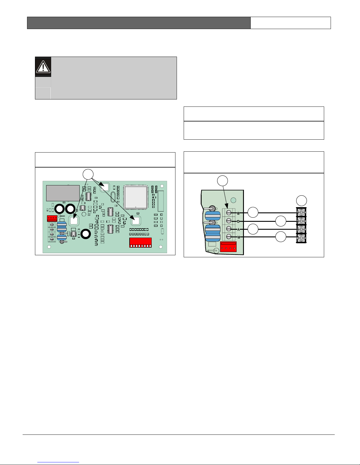
Figure 3: DX4020 Mounting Holes
1
3.2 DX4020 Wiring
Wiring connections are made from the DX4020’s data
bus terminals to the compatible control panel’s data
bus terminals.
See the control panel’s documentation for complete
wiring instructions.
Figure 4: one column wide figure
This figure box is saved as a AutoText entry called
Figure – Column Width
This is for caption text
Figure 5: DX4020 to Control Panel
SDI/Option/Data Bus Wiring
1
2
3
4
5
6
1 - DX4020 Mounting Holes
1 - DX4020 Data Bus Terminals
2 - Compatible Control Panel SDI/Option/Data
Bus Terminals
3 - Black (-) Wire
4 - Green (G) Data Wire
5 - Yellow (Y) Data Wire
6 - Red (+) Wire
Bosch Security Sys | 8/04 | F01U002192B

DX4020-EXP | Installation Guide | 4. DX4020 DIP Switch Settings EN | 5
4. DX4020 DIP Switch
Settings
Use the following DIP Switch settings for network
communication when using the DX4020.
4.1 DIP Switch Address Settings for the
D9412G/D9412, D7412G/D7412,
4.2 DIP Switch Address Settings for the
DS7240V2/DS7220V2 Control
Panels
The DS7240V2 and DS7220V2 control
panels require firmware revision 2.xx or
later for network communication.
D7212G, D9112, D7212 Control
Panels
The D9412G/D9412, D7412G/D7412,
D7212G, D9112, D7212 control panels
require firmware revision 6.3 or later for
network communication.
Set the DX4020’s DIP Switch address to 134 when
using the DX4020 on either a DS7240V2 or
DS7220V2 for network communication.
Figure 8: DIP Switch Settings for Address 134
Use SDI Bus Address 80 when using the DX4020 in
conjunction with PC9000.
Use SDI Bus Address 88 when using the DX4020 in
conjunction with RPS, or for network communication.
Figure 6: DIP Switch Settings for Address 80
1
2
OPEN
123456
1 - OPEN (UP) Position
2 - CLOSED (DOWN) Position
Figure 7: DIP Switch Settings for Address 88
=
=
78
1
2
OPEN
123456
1 - OPEN (UP) Position
2 - CLOSED (DOWN) Position
=
=
78
4.3 DIP Switch Address Settings for the
DS7400Xi Control Panel
Use Option Bus addresses 13 and 14 to send reports.
Use Option Bus address 13 to connect to RPS for
remote programming.
Figure 9: DIP Switch Settings for Address 13
1
2
OPEN
=
=
123456
1 - OPEN (UP) Position
2 - CLOSED (DOWN) Position
Bosch Security Sys | 8/04 | F01U002192B
78
1
2
OPEN
1 - OPEN (UP) Position
2 - CLOSED (DOWN) Position
123456
=
=
78
 Loading...