

Bosch DVR-3000, DVR-5000 Operator's Manual

DIVAR 3000/5000 Digital Video Recorder
DVR-3000/5000
en Operator Manual


Table of contents
1
Safety 7
1.1 Safety precautions 7
1.2 Important safety instructions 7
1.3 Important Notices 9
1.4 FCC and UL 11
1.5 Bosch notices 11
2
Short information 13
2.1 960H high resolution 13
2.2 Compression technology 13
3
Introduction 14
3.1 Digital video recorder applications 14
3.1.1 Versions 14
3.1.2 Manuals 14
3.1.3 Features 15
3.2 Unpacking 15
3.2.1 Package contents 15
3.3 Installation environment 16
3.3.1 Mounting 16
3.3.2 Ventilation 16
3.3.3 Temperature 16
3.3.4 Power Supply 16
3.3.5 Environment 16
3.4 Associated equipment 16
3.5 Warranty 16
4
Quick install 17
4.1 Connections 17
4.1.1 Primary connections 19
4.1.2 Optional connections 19
4.2 Powering up 20
4.3 Login 21
4.4 Startup Wizard 21
4.4.1 Reset startup wizard 23
4.4.2 General 23
4.4.3 Encoder 24
4.4.4 Schedule 25
4.4.5 Record 25
4.4.6 Network 26
4.5 Shutdown/Logout 26
5
Hardware setup 28
5.1 Camera connections 28
5.2 Audio connections 28
5.3 Monitor connections 28
5.3.1 VGA output 28
5.3.2 CVBS 29
5.3.3 HDMI 29
5.4 Keyboard connection (only DIVAR 5000) 29
5.5 Ethernet connection 30
DIVAR 3000/5000 Digital Video
Recorder
Table of Contents | en 3
Bosch Security Systems Operator Manual 2013.05 | 1.0 | DIVAR 3000/5000 Digital Video
Recorder

5.6 RS485 port connection 31
5.7 RS232 port connections 31
5.8 USB connectors 32
5.9 e-SATA connector (only DIVAR 5000) 32
5.10 Alarm I/O connections 33
5.10.1 Connecting the alarm input 33
5.10.2 Connecting the alarm output 34
5.11 Power supply 34
6
Configuration 35
6.1 Setting 36
6.2 General 37
6.3 Encode 39
6.3.1 Overlay 40
6.3.2 Snapshot 40
6.3.3 Copy 41
6.4 Schedule 43
6.5 Serial port 45
6.6 Network 46
6.6.1 Network settings 47
6.6.2 IP filter 48
6.6.3 NTP 49
6.6.4 PPPoE 49
6.6.5 DDNS 50
6.6.6 UPnP 51
6.6.7 EMail 52
6.6.8 FTP server 53
6.6.9 SNMP 54
6.7 Alarm 55
6.8 Detect 57
6.8.1 Motion detect region setup 59
6.8.2 Period 60
6.8.3 PTZ activation 61
6.9 Pan/Tilt/Zoom 62
6.10 Display 63
6.10.1 Tour setup 64
6.11 Default 65
6.12 Advanced 66
6.13 Hard Disk (HDD) 67
6.14 System events 68
6.15 Alarm Output 69
6.16 Record 70
6.17 Account/Users 71
6.17.1 Add user 72
6.17.2 Modify/Delete a user 73
6.17.3 Modify password 74
6.18 Auto maintain 75
6.19 TV adjust 76
6.20 Text data overlay 77
6.21 Configuration/Backup 79
4 en | Table of Contents
DIVAR 3000/5000 Digital Video
Recorder
2013.05 | 1.0 | DIVAR 3000/5000 Digital Video
Recorder
Operator Manual Bosch Security Systems

6.22 Sequence Mon B 79
7
Operating instructions 80
7.1 User controls and menus 80
7.1.1 Mouse Controls 81
7.1.2 Front panel controls 82
7.1.3 Remote control 85
7.1.4 Quick menu 87
7.1.5 Main menu 88
7.2 Live and playback 89
7.2.1 Live mode 90
7.2.2 PTZ 92
7.2.3 Sequence 92
7.2.4 Monitor A 93
7.2.5 Monitor B 93
7.3 Search/Play 93
7.4 Backup 98
7.5 Info 101
7.5.1 HDD info 102
7.5.2 Bps 103
7.5.3 Log 104
7.5.4 Version 105
7.5.5 Online users 106
7.5.6 Network info 106
7.6 Triggers and alarms 108
8
Web Client Software 110
8.1 Getting started 110
8.1.1 System requirements 110
8.1.2 Connecting to the DIVAR the first time 111
8.2 How to log on 111
8.2.1 Menu structure differences 114
8.3 Introducing the Web Live window 114
8.3.1 Playback mode 116
8.3.2 Setup mode 116
8.3.3 Alarm 117
8.3.4 About 118
8.3.5 Logout 118
9
Archive Player operation 119
9.1 Getting started 119
9.1.1 System requirements 119
9.1.2 Installation 119
9.1.3 Starting the Player 119
9.1.4 Setting 122
9.2 Camera Views 125
9.3 Checking authenticity (Watermark) 125
9.4 Exit button 126
10
Troubleshooting 127
11
Maintenance 131
11.1 Attach ESD strap 134
11.2 Replace internal battery 134
DIVAR 3000/5000 Digital Video
Recorder
Table of Contents | en 5
Bosch Security Systems Operator Manual 2013.05 | 1.0 | DIVAR 3000/5000 Digital Video
Recorder

11.3 Install HDD in DIVAR 3000 135
11.4 Install HDD in DIVAR 5000 138
11.5 Install DVD in DIVAR 3000 142
11.6 Install DVD in DIVAR 5000 144
12
Technical specifications 146
12.1 DIVAR 3000 146
12.2 DIVAR 5000 149
12.3 Standards and Directives 153
13
Appendix 155
13.1 Software licenses 155
13.1.1 Bosch software 155
13.1.2 Other licenses — copyright notices 155
13.1.3 Warranties and disclaimer of warranties 156
13.2 DVD compatibility 156
13.3 USB memory sticks 157
13.4 HDD compatibility 158
6 en | Table of Contents
DIVAR 3000/5000 Digital Video
Recorder
2013.05 | 1.0 | DIVAR 3000/5000 Digital Video
Recorder
Operator Manual Bosch Security Systems
Safety
This safety section describes safety requirements and the format used for warnings and
cautions.
Safety precautions
Warnings and caution formats
Danger!
High risk: This symbol indicates an imminently hazardous situation such as "Dangerous
Voltage" inside the product.
If not avoided, this will result in an electrical shock, serious bodily injury, or death.
!
Warning!
Medium risk: Indicates a potentially hazardous situation.
If not avoided, this could result in minor or moderate bodily injury.
!
Caution!
Low risk: Indicates a potentially hazardous situation.
if not avoided, this could result in property damage or risk of damage to the unit.
Notice!
This symbol indicates information or a company policy that relates directly or indirectly to the
safety of personnel or protection of property.
Important safety instructions
Read, follow, and retain for future reference all of the following safety instructions. Heed all
warnings on the unit and in the operating instructions before operating the unit.
1. Cleaning - Unplug the unit from the outlet before cleaning. Follow any instructions
provided with the unit. Generally, using a dry cloth for cleaning is sufficient but a moist,
fluff-free cloth or leather shammy may also be used. Do not use liquid cleaners or aerosol
cleaners.
2. Heat Sources - Do not install the unit near any heat sources such as radiators, heaters,
stoves, or other equipment (including amplifiers) that produce heat.
3. Ventilation - Any openings in the unit enclosure are provided for ventilation to prevent
overheating and ensure reliable operation. Do not block or cover these openings. Do not
place the unit in an enclosure unless proper ventilation is provided, or the manufacturer's
instructions have been adhered to.
4. Water - Do not use this unit near water, for example near a bathtub, washbowl, sink,
laundry basket, in a damp or wet basement, near a swimming pool, in an outdoor
installation, or in any area classified as a wet location. To reduce the risk of fire or
electrical shock, do not expose this unit to rain or moisture.
5. Object and liquid entry - Never push objects of any kind into this unit through openings
as they may touch dangerous voltage points or short-out parts that could result in a fire
or electrical shock. Never spill liquid of any kind on the unit. Do not place objects filled
with liquids, such as vases or cups, on the unit.
1
1.1
1.2
DIVAR 3000/5000 Digital Video
Recorder
Safety | en 7
Bosch Security Systems Operator Manual 2013.05 | 1.0 | DIVAR 3000/5000 Digital Video
Recorder

6. Lightning - For added protection during a lightning storm, or when leaving this unit
unattended and unused for long periods, unplug the unit from the wall outlet and
disconnect the cable system. This will prevent damage to the unit from lightning and
power line surges.
7. Controls adjustment - Adjust only those controls specified in the operating instructions.
Improper adjustment of other controls may cause damage to the unit. Use of controls or
adjustments, or performance of procedures other than those specified, may result in
hazardous radiation exposure.
8. Overloading - Do not overload outlets and extension cords. This can cause fire or
electrical shock.
9. Power supply cord and plug protection - Power supply cords should be routed so that
they are not likely to be walked on or pinched by items placed upon or against them,
playing particular attention to cords and plugs, convenience receptacles, and the point
where they exit from the appliance.
10. Power disconnect - Units have power supplied to the unit whenever the power cord is
inserted into the power source. The power cord plug is the main power disconnect device
for switching off the voltage for the unit.
11. Power sources - Operate the unit only from the type of power source indicated on the
label. Before proceeding, be sure to disconnect the power from the cable to be installed
into the unit.
12. Servicing - Do not attempt to service this unit yourself. Opening or removing covers may
expose you to dangerous voltage or other hazards. Refer all servicing to qualified service
personnel.
13. Damage requiring service - Unplug the power unit from the main AC power source and
refer servicing to qualified service personnel when any damage to the equipment has
occurred, such as:
–
the power supply cord or plug is damaged;
– exposure to moisture, water, and/or inclement weather (rain, snow, etc.);
– liquid has been spilled in or on the equipment;
– an object has fallen into the unit;
– unit has been dropped or the unit cabinet is damaged;
– unit exhibits a distinct change in performance;
– unit does not operate normally when the user correctly follows the operating
instructions.
14. Replacement parts - Be sure the service technician uses replacement parts specified by
the manufacturer, or that have the same characteristics as the original parts.
Unauthorized substitutions could void the warranty and cause fire, electrical shock, or
other hazards.
15. Safety check - Safety checks should be performed upon completion of service or repairs
to the unit to ensure proper operating condition.
16. Installation - Install in accordance with the manufacturer's instructions and in accordance
with applicable local codes.
17. Attachments, changes or modifications - Only use attachments/accessories specified by
the manufacturer. Any change or modification of the equipment, not expressly approved
by Bosch, could void the warranty or, in the case of an authorization agreement, authority
to operate the equipment.
8 en | Safety
DIVAR 3000/5000 Digital Video
Recorder
2013.05 | 1.0 | DIVAR 3000/5000 Digital Video
Recorder
Operator Manual Bosch Security Systems
Important Notices
Accessories - Do not place this unit on an unstable stand, tripod, bracket, or mount. The
unit may fall, causing serious injury and/or serious damage to the unit. Use only with the
cart, stand, tripod, bracket, or table specified by the manufacturer. When a cart is used, use
caution and care when moving the cart/apparatus combination to avoid injury from tip-over.
Quick stops, excessive force, or uneven surfaces may cause the cart/unit combination to
overturn. Mount the unit per the manufacturer's instructions.
All-pole power switch - Incorporate an all-pole power switch, with a contact separation of at
least 3 mm in each pole, into the electrical installation of the building. If it is needed to open
the housing for servicing and/or other activities, use this all-pole switch as the main
disconnect device for switching off the voltage to the unit.
Battery replacement - For qualified service personnel only - A lithium battery is located
inside the unit enclosure. To avoid danger of explosion, replace the battery as per
instructions. Replace only with the same or equivalent type recommended by the
manufacturer. Dispose of the replaced battery in an environmentally friendly way and not with
other solid waste. Refer all servicing to qualified service personnel.
Notice!
Batteries must not be disposed of in household waste. Dispose of batteries only at suitable
collection points and, in the case of lithium batteries, mask the poles.
For further information refer to: http://www.BoschSecurity.com/standards
!
Caution!
Class I Laser Product
Invisible laser radiation when open. Avoid exposure to beam.
Coax grounding:
–
Ground the cable system if connecting an outside cable system to the unit.
– Connect outdoor equipment to the unit's inputs only after this unit has had its grounding
plug connected to a grounded outlet or its ground terminal is properly connected to a
ground source.
– Disconnect the unit's input connectors from outdoor equipment before disconnecting the
grounding plug or grounding terminal.
– Follow proper safety precautions such as grounding for any outdoor device connected to
this unit.
U.S.A. models only - Section 810 of the National Electrical Code, ANSI/NFPA No.70, provides
information regarding proper grounding of the mount and supporting structure, grounding of
the coax to a discharge unit, size of grounding conductors, location of discharge unit,
connection to grounding electrodes, and requirements for the grounding electrode.
Disposal - Your Bosch product was developed and manufactured with high-quality material
and components that can be recycled and reused. This symbol means that electronic and
electrical appliances, which have reached the end of their working life, must be collected
and disposed of separately from household waste material. Separate collecting systems are
usually in place for disused electronic and electrical products. Please dispose of these units
at an environmentally compatible recycling facility, per European Directive 2002/96/EC.
1.3
DIVAR 3000/5000 Digital Video
Recorder
Safety | en 9
Bosch Security Systems Operator Manual 2013.05 | 1.0 | DIVAR 3000/5000 Digital Video
Recorder

!
Caution!
Electronic Surveillance - This device is intended for use in public areas only.
U.S. federal law strictly prohibits surreptitious recording of oral communications.
Electrostatic-sensitive device - Use proper CMOS/MOS-FET handling precautions to avoid
electrostatic discharge. NOTE: Wear required grounded wrist straps and observe proper ESD
safety precautions when handling the electrostatic-sensitive printed circuit boards.
Environmental statement - Bosch has a strong commitment towards the environment. This
unit has been designed to respect the environment as much as possible.
Fuse rating - For protection of the device, the branch circuit protection must be secured with
a maximum fuse rating of 16 A. This must be in accordance with NEC800 (CEC Section 60).
Grounding and polarization - This unit may be equipped with a polarized alternating current
line plug (a plug with one blade wider than the other blade). This safety feature allows the
plug to fit into the power outlet in only one way. If unable to insert the plug fully into the
outlet, contact a locally certified electrician to replace the obsolete outlet. Do not defeat the
safety purpose of the polarized plug.
Alternately, this unit may be equipped with a 3-pole grounding plug (a plug with a third pin for
earth grounding). This safety feature allows the plug to fit into a grounded power outlet only.
If unable to insert the plug into the outlet, contact a locally certified electrician to replace the
obsolete outlet. Do not defeat the safety purpose of the grounding plug.
Moving - Disconnect the power before moving the unit. Move the unit with care. Excessive
force or shock may damage the unit and the hard disk drives.
Outdoor signals - The installation for outdoor signals, especially regarding clearance from
power and lightning conductors and transient protection, must be in accordance with NEC725
and NEC800 (CEC Rule 16-224 and CEC Section 60).
Permanently connected equipment - Incorporate a readily accessible disconnect device
external to the equipment.
Pluggable equipment - Install the socket outlet near the equipment so it is easily accessible.
Rack-mount (only DIVAR 5000 family)
–
Elevated Operating Ambient - If installed in a closed or multi-unit rack assembly, the
operating ambient temperature of the rack environment may be greater than room
ambient. Therefore, consideration should be given to installing the equipment in an
environment compatible with the maximum ambient temperature (Tma) specified by the
manufacturer.
– Reduced Air Flow - Installation of the equipment in a rack should be such that the amount
of air flow required for safe operation of the equipment is not compromised.
– Mechanical loading - Mounting of the equipment in the rack should be such that a
hazardous condition is not achieved due to uneven mechanical loading.
– Circuit Overloading - Consideration should be given to the connection of the equipment
to the supply circuit and the effect that overloading of the circuits might have on
overcurrent protection and supply wiring. Appropriate consideration of equipment
nameplate ratings should be used when addressing this concern.
– Reliable Earthing - Reliable earthing of rack-mounted equipment should be maintained.
Particular attention should be given to supply connections other than direct connections
to the branch circuit (e.g. use of power strips).
SELV - All the input/output ports are Safety Extra Low Voltage (SELV) circuits. SELV circuits
should only be connected to other SELV circuits.
10 en | Safety
DIVAR 3000/5000 Digital Video
Recorder
2013.05 | 1.0 | DIVAR 3000/5000 Digital Video
Recorder
Operator Manual Bosch Security Systems

Video loss - Video loss is inherent to digital video recording; therefore, Bosch Security
Systems cannot be held liable for any damage that results from missing video information. To
minimize the risk of lost digital information, Bosch Security Systems recommends multiple,
redundant recording systems, and a procedure to back up all analog and digital information.
FCC and UL
FCC & ICES Information
(U.S.A. and Canadian Models Only)
This equipment has been tested and found to comply with the limits for a Class B digital
device, pursuant to Part 15 of the FCC Rules and ICES-003 of Industry Canada. These limits
are designed to provide reasonable protection against harmful interference when the
equipment is operated in a residential installation. This equipment generates, uses, and can
radiate radio frequency energy and, if not installed and used in accordance with the
instruction manual, may cause harmful interference to radio communications. However, there
is no guarantee that interference will not occur in a particular installation. If this equipment
does cause harmful interference to radio or television reception, which can be determined by
turning the equipment off and on, the user is encouraged to try to correct the interference by
one or more of the following measures:
–
Reorient or relocate the receiving antenna;
– Increase the separation between the equipment and the receiver;
– Connect the equipment into an outlet on a circuit different from that to which the
receiver is connected;
– Consult the dealer or an experienced radio/TV technician for help.
Intentional or unintentional modifications, not expressly approved by the party responsible for
compliance, shall not be made. Any such modifications could void the user's authority to
operate the equipment. If necessary, the user should consult the dealer or an experienced
radio/television technician for corrective action.
The user may find the following booklet, prepared by the Federal Communications
Commission, helpful: How to Identify and Resolve Radio-TV Interference Problems. This
booklet is available from the U.S. Government Printing Office, Washington, DC 20402, Stock
No. 004-000-00345-4.
UL Disclaimer
Underwriter Laboratories Inc. ("UL") has not tested the performance or reliability of the
security or signaling aspects of this product. UL has only tested fire, shock and/or casualty
hazards as outlined in UL's Standard(s) for Safety for Information Technology Equipment, UL
60950-1. UL Certification does not cover the performance or reliability of the security or
signaling aspects of this product.
UL MAKES NO REPRESENTATIONS, WARRANTIES, OR CERTIFICATIONS WHATSOEVER
REGARDING THE PERFORMANCE OR RELIABILITY OF ANY SECURITY OR SIGNALING-RELATED
FUNCTIONS OF THIS PRODUCT.
Bosch notices
Copyright
This manual is the intellectual property of Bosch Security Systems and is protected by
copyright.
All rights reserved.
1.4
1.5
DIVAR 3000/5000 Digital Video
Recorder
Safety | en 11
Bosch Security Systems Operator Manual 2013.05 | 1.0 | DIVAR 3000/5000 Digital Video
Recorder

Trademarks
All hardware and software product names used in this document are likely to be registered
trademarks and must be treated accordingly.
NOTE!
This manual has been compiled with great care and the information it contains has been
thoroughly verified. The text was complete and correct at the time of printing. The ongoing
development of the products may mean that the content of the user guide can change without
notice. Bosch Security Systems accepts no liability for damage resulting directly or indirectly
from faults, incompleteness or discrepancies between the user guide and the product
described.
12 en | Safety
DIVAR 3000/5000 Digital Video
Recorder
2013.05 | 1.0 | DIVAR 3000/5000 Digital Video
Recorder
Operator Manual Bosch Security Systems

Short information
The Bosch Video Recorder
DIVAR 3000/5000 is a multi-channel digital recorder that uses the
latest 960H high resolution technology, plus modern compression techniques. Simultaneous
monitoring, recording and playback are guided remote or local by simple menu selections and
operator commands. If required, a variety of optional storage capacities can be added
(including built-in HDDs and/or a DVD writer).
The DIVAR 3000/5000records multiple video and audio signals while simultaneously providing
live multi-screen viewing and playback. Comprehensive search and playback functions provide
quick recall and viewing of recorded video.
960H high resolution
960H refers to a new class of advanced imaging sensors that provide the highest levels of
image quality available for the PAL and NTSC standards. Bosch cameras with these sensors
serve as the bridge between standard resolution and high definition solutions. Ideal for
capturing fine scene details, they provide the DIVAR with images that are 976 pixels wide with
30 percent higher resolution than previous generation analog 760H sensors.
Compression technology
The
DIVAR 3000/5000 takes advantage of the latest H.264 (video) and G.711 (audio)
compression technology to dramatically reduce storage and bandwidth required while still
producing superb image and audio quality.
2
2.1
2.2
DIVAR 3000/5000 Digital Video
Recorder
Short information | en 13
Bosch Security Systems Operator Manual 2013.05 | 1.0 | DIVAR 3000/5000 Digital Video
Recorder

Introduction
Digital video recorder applications
Recording
The DIVAR 3000/5000
is very easy to use – simply connect the camera(s), apply power, and let
the unit record automatically in the background with no further intervention required.
The H.264 compression function significantly reduces the file size of recordings without
sacrificing image quality. The DIVAR can record at up to 25 (PAL) / 30 (NTSC) images per
second, per channel at 960H resolution.
Dome Control
The DIVAR can control pan/tilt/zoom (PTZ) equipment via RS‑485 / RS‑232 serial
communications. PTZ devices, including the Bosch AutoDome and a number of third party
domes, are supported.
Alarms
All models have extensive alarm handling functions and telemetry control. Alarm functions
include local inputs and relay outputs, plus motion detection in user-defined areas. If an alarm
is detected, the DIVAR can:
– send an e-mail notification and/or FTP push
– display an on-screen message
– sound a buzzer and/or show a warning light
Local control
The unit can be easily operated and programmed via the on-screen display menu system using
the front panel control keys, the supplied mouse, or the supplied remote control. A choice of
monitor outputs provides full-screen, multi-screen and sequenced viewing.
Video inputs/outputs, audio inputs/output, and alarm inputs/outputs are located on the rear
panel. Three video connectors (CVBS/VGA/HDMI) provide simultaneous output for monitor A
for full-screen or multi-screen live display and playback (the display can be zoomed). A single
CVBS connector provides output to monitor B (spot monitor) for full-screen or multi-screen
live viewing.
Network control
Use the PC software or built-in web application via a network for live viewing, playback, and
configuration. The DIVAR includes an authenticity check for both local and remote archived
video/audio playback, ensuring recording integrity. An Archive Player is provided for playback
of secure video files and to check if video is authentic.
Smartphone App
The DIVAR Viewer App for iOS and Android devices is available for live viewing and PTZ control
from anywhere in the world. Watch live video from all cameras connected to the DVR, and
control focus, pan, tilt and zoom on PTZ-enabled cameras.
Versions
The
DIVAR 3000/5000 models are available in 4, 8 and 16 channel versions with a variety of
hard drive capacities (max. four for DIVAR 5000 or two for DIVAR 3000), and if required, an
internal DVD writer.
Manuals
This manual contains information about:
– Quick Installation - a brief overview on how to set up and install the product.
– Hardware Setup - a detailed description for installers on how to install the product.
3
3.1
3.1.1
3.1.2
14 en | Introduction
DIVAR 3000/5000 Digital Video
Recorder
2013.05 | 1.0 | DIVAR 3000/5000 Digital Video
Recorder
Operator Manual Bosch Security Systems

– Operation - a detailed description for end-users on how to operate the unit.
–
Web Control and Archive Player - a detailed description for end-users and administrators
on how to set up and operate the Web Control and Archive Player software.
Features
The DIVAR 3000/5000 has the following features:
– 4, 8 or 16 auto-terminating camera inputs with 960H resolution
– 4 audio inputs (plus 1 MIC input) and 1 audio output
– Simultaneous live viewing, recording, playback, and remote streaming
– Choice of CVBS/VGA/HDMI monitor A outputs
– 10/100/1000Base-T Ethernet port for local or wide area network connection
– RS‑485 / RS‑232 serial ports to control movable cameras (PTZ)
– IR remote control, front panel keyboard and mouse support for camera control
– Secret (covert) recording channel that can be locked for unauthorized viewing
– Full-screen and multi-screen display capabilities in live and playback modes for monitors
– Maximum 16 switching (alarm) inputs and maximum 6 alarm outputs
– Alarm notification (screen, audible, FTP, e-mail) and automatic record activation
– Motion detection and video loss detection
– DIVAR Viewer App for live and PTZ control on Smartphone (iOS and Android)
– Supports Bosch and Pelco protocols
– Video loop-through (only DIVAR 5000)
– Intui keyboard support (only DIVAR 5000)
– e-SATA support (only DIVAR 5000)
Unpacking
Inspect the package for visible damage. If any items appear to have been damaged during
transport, notify the shipping company. Unpack carefully. This is electronic equipment and
should be handled with care to prevent damage to the unit. Do not attempt to use the unit if
any components are damaged. If any items are missing, notify your customer service
representative or Bosch Security Systems sales representative. The shipping carton is the
safest container in which to transport the unit. Save it and all packing materials for future use.
If the unit must be returned, use the original packing materials.
Package contents
Check for the following items:
–
Digital Video Recorder (DIVAR 3000 or 5000 unit)
– Quick Install guide
– Operator manual (this manual)
– Optical USB mouse
– CD-ROM containing software, the Archive Player and documentation
– Power supply cords
– External 12 VDC power adaptor (only for DIVAR 3000)
– Terminal blocks for external I/O connectors
– IR remote Control with 2 AA (1.5 V) Batteries
– 19-inch rack mount brackets + screws (only for DIVAR 5000)
– Split cable for 16-ch loop-through to 25-pin D connector (only for DIVAR 5000 16-ch)
– HDD/DVD mounting material (if not already built-in)
3.1.3
3.2
3.2.1
DIVAR 3000/5000 Digital Video
Recorder
Introduction | en 15
Bosch Security Systems Operator Manual 2013.05 | 1.0 | DIVAR 3000/5000 Digital Video
Recorder

Installation environment
Mounting
The
DIVAR 3000/5000 is supplied as a desktop unit (the DIVAR 5000 can also be optionally
rack mounted with the supplied brackets).
Ventilation
Ensure that the location planned for the installation of the unit is well ventilated. Take note of
the locations of the cooling vents in the unit's enclosure and ensure that they are not
obstructed as this might cause the unit to fail and void the warranty.
Temperature
Observe the unit's ambient temperature specifications when choosing an installation space.
Extremes of heat or cold beyond the specified operating temperature limits may cause the unit
to fail and void the warranty. Do not install the unit on top of hot equipment.
Power Supply
Ensure that the site's AC power supply is stable and within the rated voltage of the unit. If the
site's AC power is likely to have spikes or power dips, use power line conditioning or an
uninterrupted power supply (UPS) to prevent unit failure.
Environment
The unit is designed to operate in a clean office environment. Elevated levels of dust may
cause the unit to fail and void the warranty.
Associated equipment
A typical system could contain the following components (not included with the unit):
–
Primary CVBS, VGA or HDMI input monitor for multiscreen monitoring (monitor A)
– Second CVBS input monitor for spot/alarm monitoring (monitor B)
– Cameras with 1 Vpp composite video outputs
– Amplified microphone
– Audio amplifier with speaker(s)
– Video coaxial cable with BNC connectors for connecting the video signals
– Audio cable with RCA connectors for connecting audio signals.
– AC power supply outlet for the power supply unit that allows for secure isolation
– PC and network for the remote application
– Pan/tilt/zoom control units
– Bosch keyboard (only for DIVAR 5000)
– RJ11 adaptor to connect Bosch keyboard (only for DIVAR 5000)
Warranty
Failure to follow the Safety Instructions, Installation Instructions, and any other instructions in
this manual may result in damage to the unit and void the warranty.
3.3
3.3.1
3.3.2
3.3.3
3.3.4
3.3.5
3.4
3.5
16 en | Introduction
DIVAR 3000/5000 Digital Video
Recorder
2013.05 | 1.0 | DIVAR 3000/5000 Digital Video
Recorder
Operator Manual Bosch Security Systems
Quick install
To get the unit operational, perform the following quick install steps:
1.
Make all the hardware connections – see Connections, page 17.
2. Power up the system – see Powering up, page 20.
3. Log in – see Login, page 21.
4. Correctly configure your system software with the Startup wizard (this appears the first
time the unit is started) – see Startup Wizard, page 21.
After completing this initial setup, the system is ready to run and will show a live view of the
camera image(s). If required, you can alter the settings later using the menus and/or factory
defaults, or you can run the Startup wizard again.
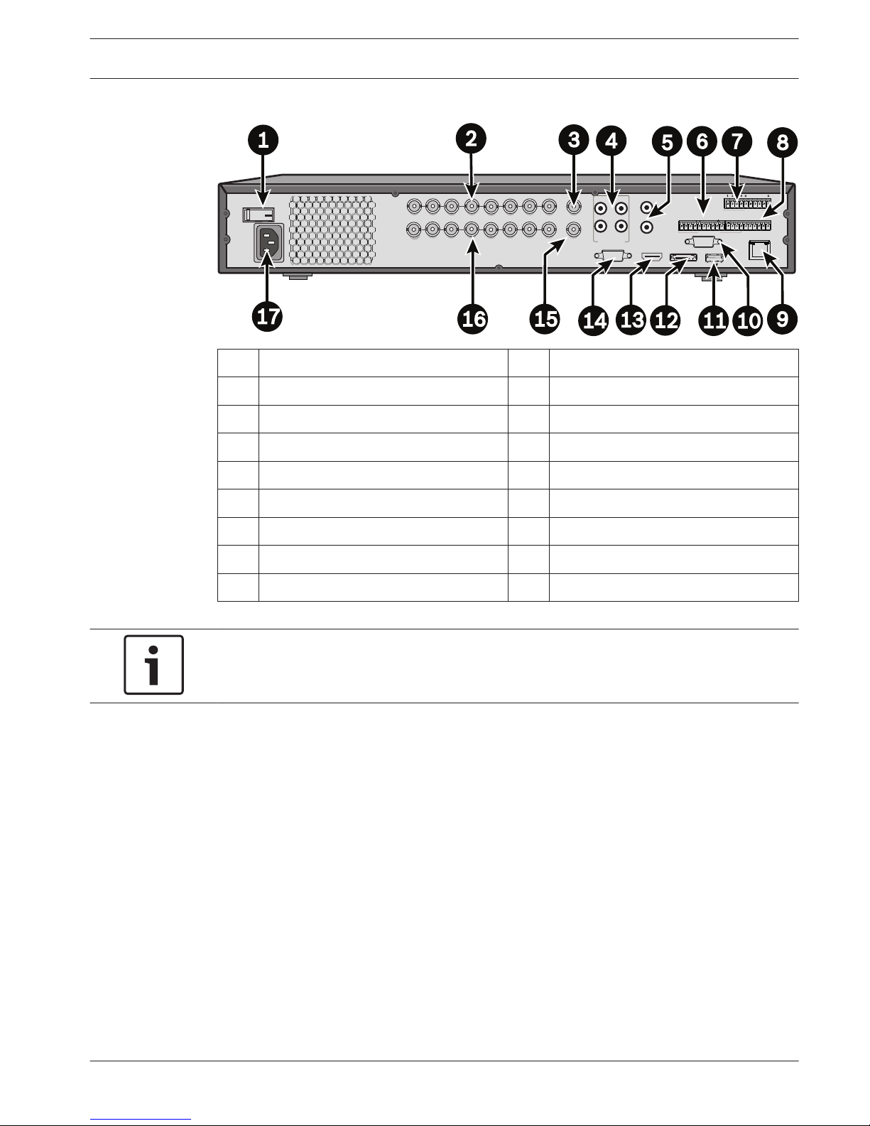
Connections
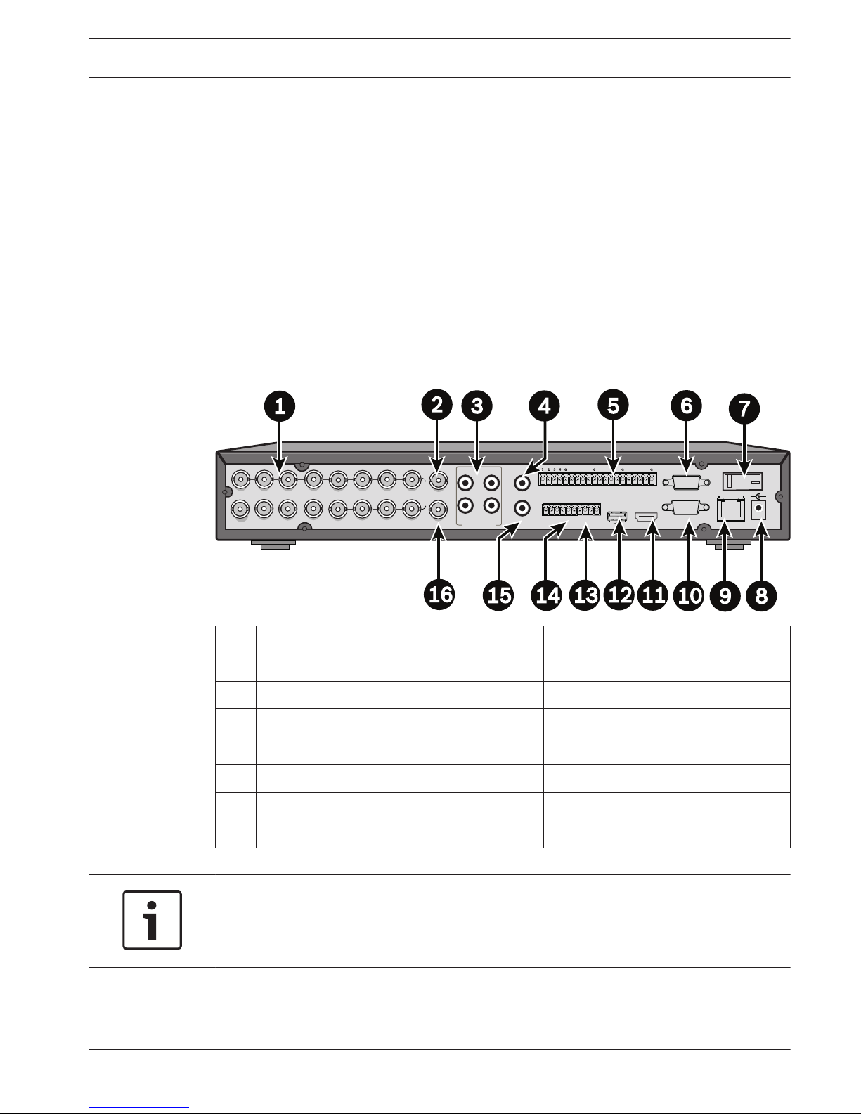
Connections on back of DIVAR 3000 (16-channel version)
12VDC
5
6 7 8 9 10 11 12 13 14 15 16
+
-
1
2
3
4
ALARM OUT
RS-485
A
UDIO OUT
ETHERNET
C3
ALARM IN
G
+
_
G
NO3
NO1
NO2
C2
C1
AUDIO IN
0
ON
OFF
HDMI MON
.A
RS-232
VGA MON.A
MIC IN
1
2
3
4
5
6
7
8
9
1
0
11
12
13
14
15
16
VIDEO IN
CVBS MON. B
CVBS MON. A
1 Camera inputs 9 RJ45 ethernet connector
2 CVBS output - Monitor A 10 VGA output - Monitor A
3 Audio inputs 11 HDMI output - Monitor A
4 Audio output 12 USB connector
5 Alarm inputs 13 RS485 connector for Dome control
6 RS232 connector for Dome control 14 Alarm outputs
7 Power ON/OFF switch 15 Microphone input
8 12 VDC Power connector 16 CVBS output - Monitor B
Notice!
The 4- and 8-channel DIVAR 3000 models have a slightly different back panel. Video in
connectors 5 to 16 for 4-channel are covered, and video out connectors 9 to 16 for 8-channel
are covered.
4
4.1
DIVAR 3000/5000 Digital Video
Recorder
Quick install | en 17
Bosch Security Systems Operator Manual 2013.05 | 1.0 | DIVAR 3000/5000 Digital Video
Recorder
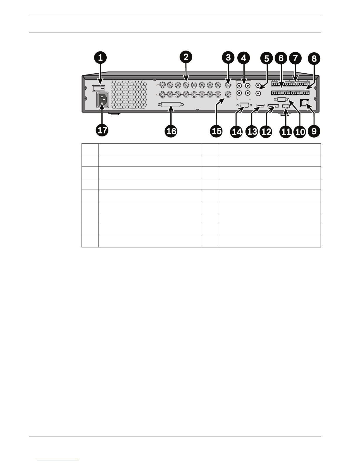
Connections on back of DIVAR 5000 (16-channel)
5 6 7 8 9 10 11 12 13 14 15 16
1
2
3
4
ALARM OUT
RS-485
A
UDIO OUT
ETHERNET
C3
ALARM IN
G
+
_
G
NO3
NO1
NO2
C2
C1
AUDIO IN
HDMI MON.A
RS-232
VGA MON.A
MIC IN
1
2
3
4
5
6
7
8
9
10
11
12
13
14
15
16
CVBS MON. B
CVBS MON. A
VIDEO IN
e-SATA
G
+
_
G
+12V
CTRL
C5
NO5
NO4
C4
KEYBOARD
+12V
0
ON
OFF
VIDEO OUT
1 Power ON/OFF switch 10 RS232 connector for Dome control
2 Camera inputs 11 USB connector
3 CVBS output - Monitor A 12 e-SATA connector
4 Audio inputs 13 HDMI output - Monitor A
5 Audio output and MIC IN connector 14 VGA output - Monitor A
6 Alarm outputs 15 CVBS output - Monitor B
7 Alarm inputs 16 Video out (loop through)
8 RS485 and keyboard connectors 17 Power connector
9 RJ45 ethernet connector
18 en | Quick install
DIVAR 3000/5000 Digital Video
Recorder
2013.05 | 1.0 | DIVAR 3000/5000 Digital Video
Recorder
Operator Manual Bosch Security Systems
Connections on back of DIVAR 5000 (4/8-channel)
5 6 7 8
1
2
3
4
ALARM OUT
RS-485
A
UDIO OUT
ETHERNET
C3
ALARM IN
G
+
_
G
NO3
NO1
NO2
C2
C1
AUDIO IN
HDMI MON.A
RS-232
VGA MON.A
MIC IN
1
1
2
2
3
3
4
4
5
5
6
6
7
7
8
8
CVBS MON. B
CVBS MON. A
VIDEO OUT
VIDEO IN
e-SATA
G
+
_
G
+12V
CTRL
C5
NO5
NO4
C4
KEYBOARD
+12V
0
ON
OFF
1 Power ON/OFF switch 10 RS232 connector for Dome control
2 Camera inputs 11 USB connector
3 CVBS output - Monitor A 12 e-SATA connector
4 Audio inputs 13 HDMI output - Monitor A
5 Audio output and MIC IN connector 14 VGA output - Monitor A
6 Alarm outputs 15 CVBS output - Monitor B
7 Alarm inputs 16 Video out (loop through)
8 RS485 and keyboard connectors 17 Power connector
9 RJ45 ethernet connector
Notice!
The 4-channel DIVAR 5000 models have a slightly different back panel (video in/out
connectors 5 to 8 are covered).
Primary connections
1.
Connect the cameras to the VIDEO IN BNC connectors.
2. Connect monitor A to the VGA MON A output, or the HDMI MON A output, or the CVBS
MON A output.
3. Connect the USB mouse to a USB port (front or back panel).
For first time use, the NTSC or PAL selection will be determined by the camera type (NTSC or
PAL) connected to VIDEO IN 1 in step 1. If no camera is connected to VIDEO IN 1 during first
time use, the video standard will be default and can be eventually set in the Startup Wizard.
Optional connections
1. Connect monitor B to the CVBS MON B connector.
2. Connect up to 4 audio signals to the AUDIO IN RCA (CINCH) inputs.
3. Connect 1 microphone to the MIC IN RCA (CINCH) output.
4. Connect 1 AUDIO OUT RCA (CINCH) output to the monitor or an audio amplifier.
5. Connect up to 16 ALARM IN inputs (via the supplied terminal blocks).
6. Connect up to 6 ALARM OUT outputs (via the supplied terminal blocks).
7. Connect a pan/tilt/zoom control unit to the RS-485 or RS-232 port.
4.1.1
4.1.2
DIVAR 3000/5000 Digital Video
Recorder
Quick install | en 19
Bosch Security Systems Operator Manual 2013.05 | 1.0 | DIVAR 3000/5000 Digital Video
Recorder

8. Connect to your network via the ETHERNET connector.
9.
Connect extra video out cables to the VIDEO OUT ports if loop through is required to
other devices (only for DIVAR 5000).
10. If required, connect a Bosch Intuikey keyboard cable to the KEYBOARD connector using
the supplied adaptor (only for DIVAR 5000).
Powering up
For the DIVAR 3000:
1.
Switch on all connected equipment.
2. Connect the external power adaptor to the AC power outlet.
3. Connect the DC power cord to the 12 VDC connector on the unit.
4. Turn on the unit power ON/OFF switch on the rear of the unit.
For the DIVAR 5000:
1. Switch on all connected equipment.
2. Connect the power cable to the AC power outlet.
3. Turn on the unit power ON/OFF switch on the rear of the unit.
4.2
20 en | Quick install
DIVAR 3000/5000 Digital Video
Recorder
2013.05 | 1.0 | DIVAR 3000/5000 Digital Video
Recorder
Operator Manual Bosch Security Systems
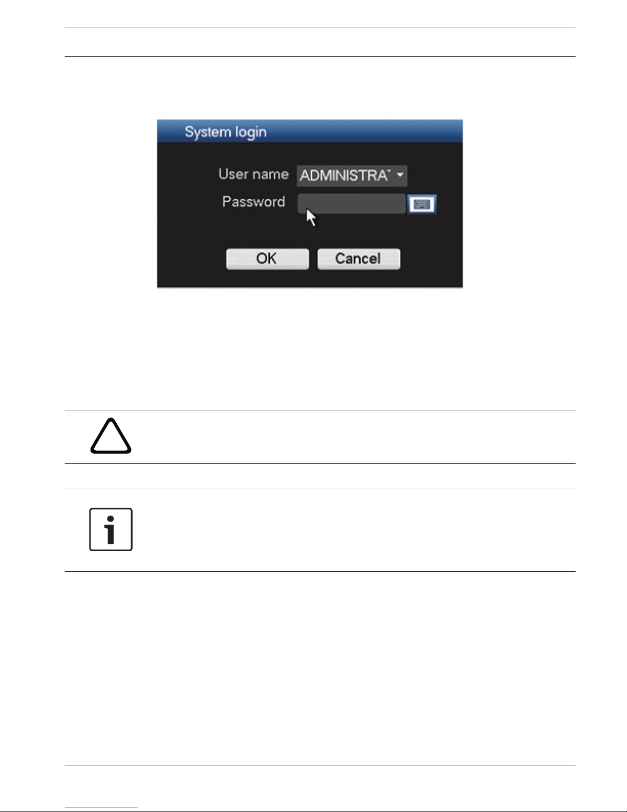
Login
The system login interface is shown in the following figure:
Figure 4.1: Login
When you startup the system for the first time, the Startup Wizard appears where you can
setup the system software. Here the default User ID is ADMINISTRATOR and the default
password is 000000 (six zeros).
Use the supplied USB mouse, front panel, remote control or keyboard (only on DIVAR 5000) to
input data and commands.
!
Caution!
Unauthorized system use
For security reason, please alter your password after you first login.
Notice!
Account lock
If you incorrectly login 5 consecutive times within a 30 minute period, the system will issue an
alarm and the account is locked; you must wait 30 minutes again for the account to be
unlocked.
When required, you can logout from the user interface using the Shutdown menu – see
Shutdown/Logout, page 26.
Startup Wizard
The Startup Wizard opens automatically after you log in for the first time. See following
screen:
4.3
4.4
DIVAR 3000/5000 Digital Video
Recorder
Quick install | en 21
Bosch Security Systems Operator Manual 2013.05 | 1.0 | DIVAR 3000/5000 Digital Video
Recorder
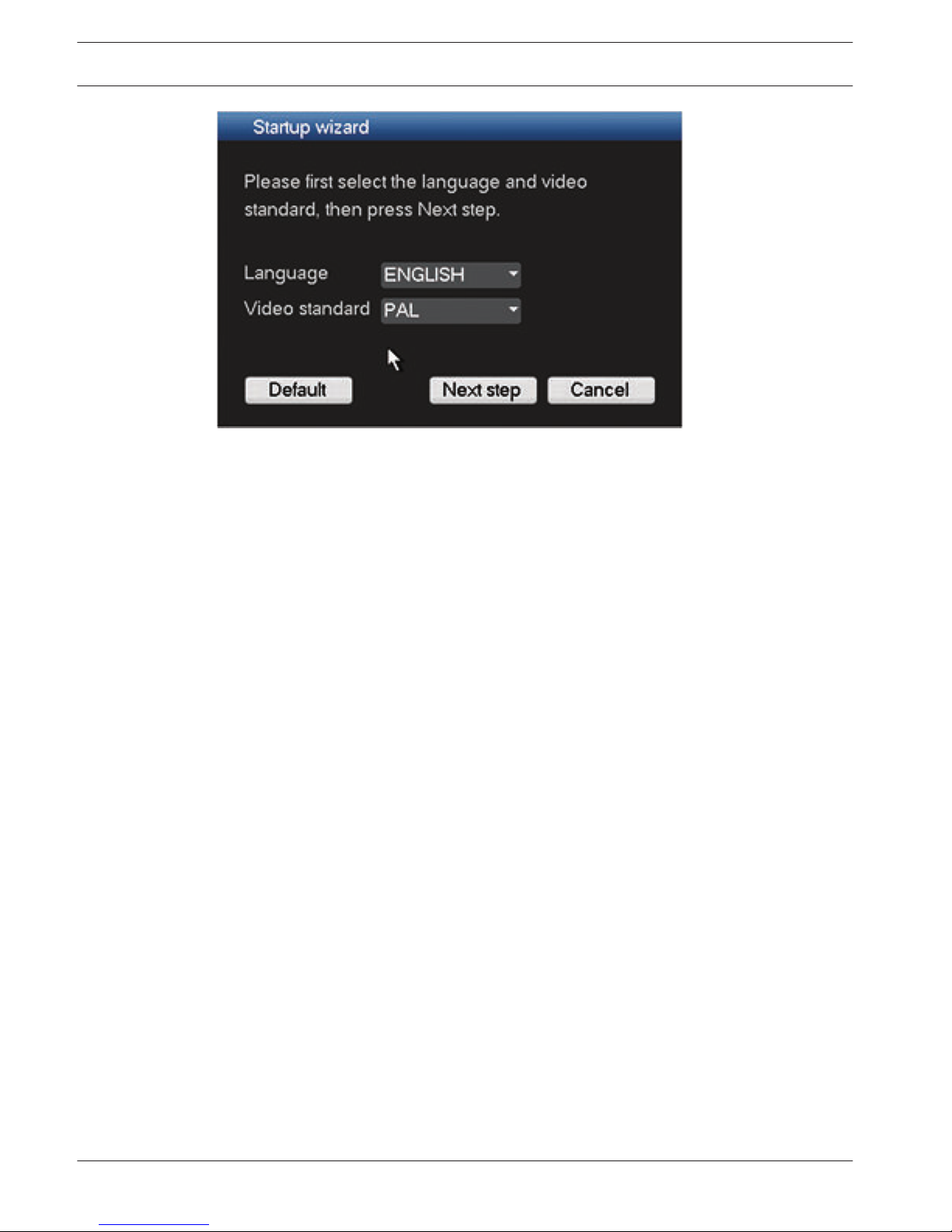
Figure 4.2: Startup wizard first screen
Assign here your preferred language and video standard from the drop-down menus and click
<Next step>. The wizard will guide you through the following steps:
1. Choose to reset the startup wizard to run after the next system restart – see Reset startup
wizard, page 23.
2. Assign General settings – see General, page 23.
3. Assign Encoder settings – see Encoder, page 24.
4. Assign Schedule settings – see Schedule, page 25.
5. Assign Record settings – see Record, page 25.
6. Assign Network settings – see Network, page 26.
7. Finish the startup by clicking <Finished>.
8. Confirm the setup by clicking <OK>.
After the Startup Wizard is finished, the unit is set in active view mode with 1 to 16 camera
images on the display. If required, this display can be changed by right-clicking the mouse to
activate a quick menu.
Use the following buttons to navigate through the wizard screens and assign your correct user
settings:
– <Cancel> exit the Startup wizard and immediately access the DIVAR user interface (this
action will automatically install all factory defaults for the remaining Startup wizard
screens)
– <Next Step> go to the next wizard screen.
– <Previous step> return to the previous Startup wizard screen
– <Default> assign the factory defaults for the current setup screen
– <Copy> copy the current screen settings for a channel to other channels
22 en | Quick install
DIVAR 3000/5000 Digital Video
Recorder
2013.05 | 1.0 | DIVAR 3000/5000 Digital Video
Recorder
Operator Manual Bosch Security Systems
Reset startup wizard
Figure 4.3: Startup wizard reset
If required, select the check box here to activate the Startup wizard after the next system
restart. This is only useful if you need to reconfigure the system during the next startup. If
required, you can also reset this mode in the General screen.
Click <Next step> for the next Startup wizard screen (General settings).
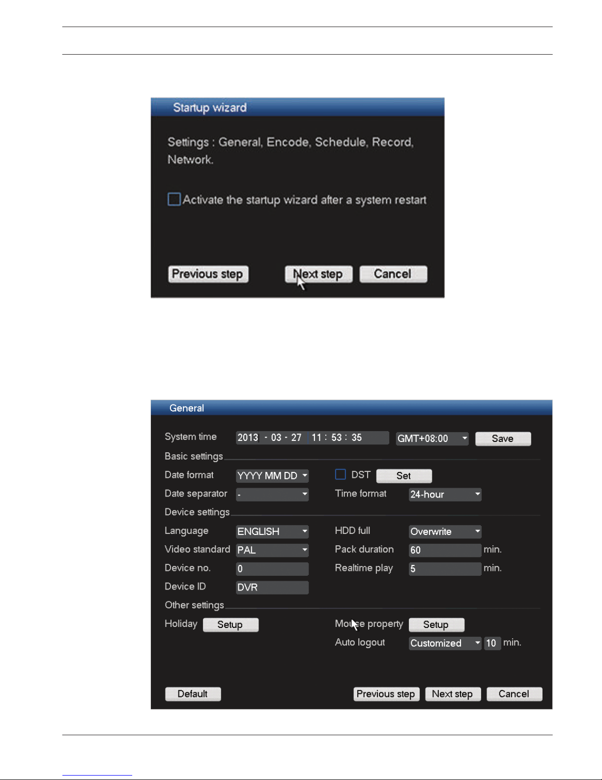
General
Figure 4.4: Startup general
4.4.1
4.4.2
DIVAR 3000/5000 Digital Video
Recorder
Quick install | en 23
Bosch Security Systems Operator Manual 2013.05 | 1.0 | DIVAR 3000/5000 Digital Video
Recorder
Check the general settings on this screen:
–
If they are correct, press <Next step> to go to the next Startup wizard screen (Encoder
settings).
– If changes are required, use the drop-down menus and entry fields to assign the correct
settings then <Next step> to move to the Encoder Startup wizard screen (if you change
the system time and/or date, click <Save> before continuing).
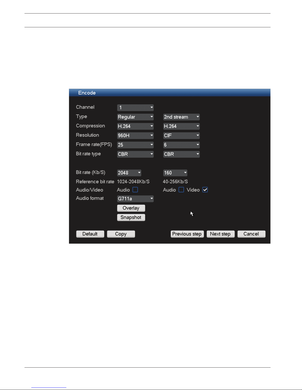
Encoder
Figure 4.5: Startup encode
Assign here the encoder settings and click <Next step> for the next Startup wizard screen
(Schedule settings). To save time when setting up channels, use <Copy> to copy settings from
one channel to other(s).
4.4.3
24 en | Quick install
DIVAR 3000/5000 Digital Video
Recorder
2013.05 | 1.0 | DIVAR 3000/5000 Digital Video
Recorder
Operator Manual Bosch Security Systems
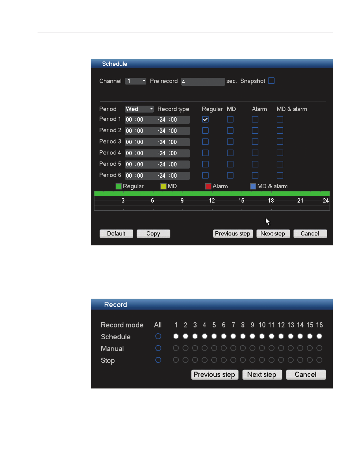
Schedule
Figure 4.6: Startup schedule
Assign here all the schedule settings and click <Next step> for the next Startup wizard screen
(Record
settings). To save time when setting up channels, use <Copy> to copy settings from
one channel to other(s).
Record
Figure 4.7: Startup Record
Assign here all the record settings and click <Next step> for the next Startup wizard screen
(Network settings):
–
Schedule: The selected channels will record according to the schedule setup (see
previous setup screen)
– Manual: selected channels will automatically begin recording
4.4.4
4.4.5
DIVAR 3000/5000 Digital Video
Recorder
Quick install | en 25
Bosch Security Systems Operator Manual 2013.05 | 1.0 | DIVAR 3000/5000 Digital Video
Recorder
– Stop: No recording on the selected channels
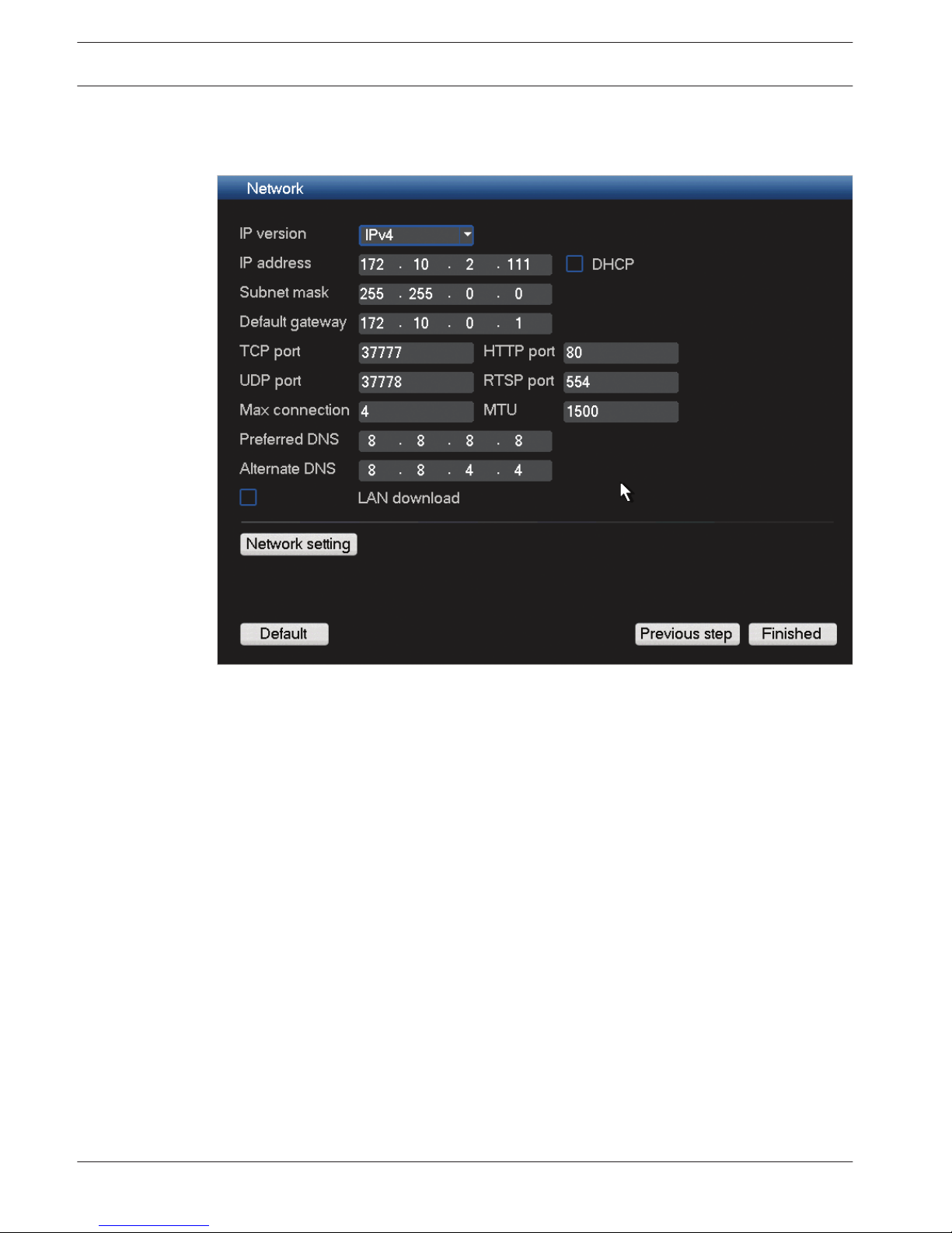
Network
Figure 4.8: Startup network
Assign here all the network settings and click <Finished>
to complete the Startup wizard (you
will need to confirm the setup by clicking <OK>). You are now ready to start operating the
system.
Operating the system
The system will automatically display the active view mode (with a maximum 16 camera
views). From here you can operate your system using the mouse, remote control or front
panel.
When you eventually need to log off from your system (or shut down completely), use the
Shutdown menu – see Shutdown/Logout, page 26.
Shutdown/Logout
1.
Right-click the-mouse to access the Quick menu; from here choose the option Main
menu.
2. Select <Shutdown> on the main menu for the Shutdown dialog box.
3. Choose Logout user from the drop-down options.
4.4.6
4.5
26 en | Quick install
DIVAR 3000/5000 Digital Video
Recorder
2013.05 | 1.0 | DIVAR 3000/5000 Digital Video
Recorder
Operator Manual Bosch Security Systems
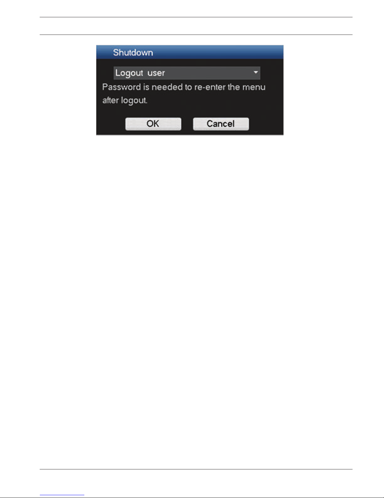
Other options on the drop-down menu are:
– Shutdown
– Restart system
– Switch user.
Logout with power button
Another way to stop all operations is:
1.
Press the power button on the front panel for at least 3 seconds.
2. Switch off the power button in the rear panel to turn off the DVR.
Start up the system again by turning on the power button on the rear panel – a new login
screen will appear.
Auto Resume after Power Failure
The system will automatically backup video recordings and resume the previous working
status after a power failure.
DIVAR 3000/5000 Digital Video
Recorder
Quick install | en 27
Bosch Security Systems Operator Manual 2013.05 | 1.0 | DIVAR 3000/5000 Digital Video
Recorder

Hardware setup
This chapter contains detailed information about the hardware installation and connection of
external equipment to the unit. The connector types and their pin signals are described. Most
of the connectors are located at the rear panel of the unit (see Connections, page 17). For
convenience, one USB port is located on the front of the unit to connect a mouse or memory
device.
All the input/output ports are Safety Extra Low Voltage (SELV) circuits. SELV circuits should
only be connected to other SELV circuits.
Camera connections
Connect cameras to the VIDEO IN connectors on the back of the unit using 75 ohm video
coaxial cables with BNC connectors. Optionally on the DIVAR 5000 family, this signal can be
looped through to other equipment via the corresponding VIDEO OUT connectors (or the
video out D-connector on the DIVAR 5000 16-channel model). The camera input connectors
are auto-terminating. There is no need to add a terminator to the output connector if no
additional equipment is connected.
If the camera signal is looped through to additional equipment, make sure that the end of the
video connection is terminated with 75 ohm termination.
The DIVAR family can be configured as a PAL or NTSC unit by manually setting the TV standard
to PAL or NTSC in the General setup menu.
Specifications
Input signal: Composite video 1 Vpp, 75 ohm
TV standard: PAL/NTSC, menu select
Connector type: BNC looped-through, automatic termination
Audio connections
The DIVAR supports up to 4 audio inputs and 1 audio output, plus a Mic in port. Connect using
audio cable with RCA (CINCH) compatible connectors.
Specifications
Input signal: Mono RCA (CINCH), 1 Vpp, 10 kOhm
Audio output signal: Mono RCA (CINCH), 1 Vpp, 5 kOhm
Bidirectional (MIC IN): Mono talk input RCA, 200 to 3000 mV, 10 kOhm
Monitor connections
Up to three monitors can be simultaneously connected through the VGA MON. A,
HDMI MON. A or CVBS MON. A connections for live viewing, playback and menus). A single
monitor can be connected through the CVBS MON. B connection for live viewing.
VGA output
Connect the unit to a VGA monitor using standard VGA cable. It is recommended to use
17” monitors or larger when using LCD.
Specifications
Output signal: VGA
Resolution: 1024x768 (4:3), 1280x720 (5:4), 1280x1024 and 1920x1080 for Monitor A
Color: True color (32 bit)
Connector type: D-SUB
5
5.1
5.2
5.3
5.3.1
28 en | Hardware setup
DIVAR 3000/5000 Digital Video
Recorder
2013.05 | 1.0 | DIVAR 3000/5000 Digital Video
Recorder
Operator Manual Bosch Security Systems
CVBS
Connect the monitor A CVBS and/or monitor B CVBS output to monitors using 75 ohm video
coaxial cables with BNC connectors.
Specifications
Output signal: Composite video 1 Vpp, 75 ohm, Sync. 0.3 Vpp ±10%
Resolution: 704x576 PAL, 704x480 NTSC
Connector type: BNC
HDMI
Connect the unit to a HDMI equivalent monitor using standard HDMI cable.
Specifications
Output signal: Digital RGB, 165 MHz
Resolution: 1920x1080, 1280x1024, 1280x720, 1024x768
Connector type: HDMI
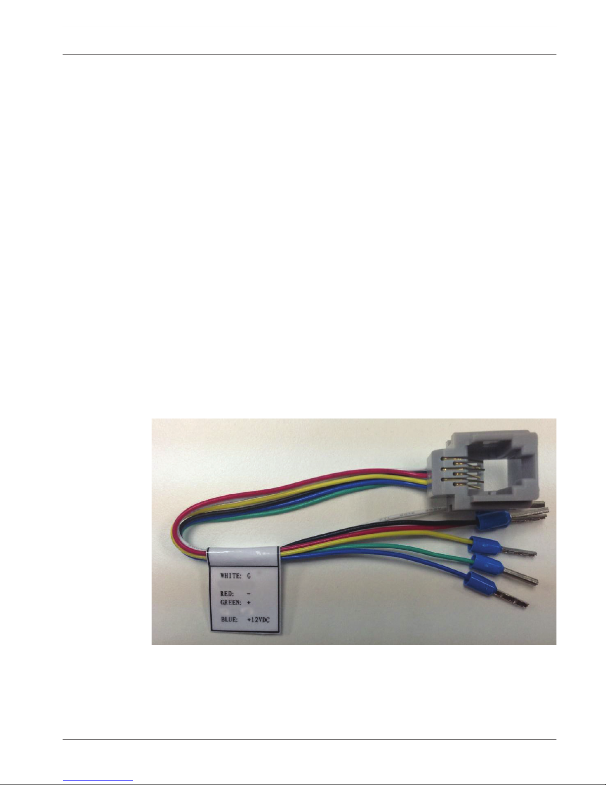
Keyboard connection (only DIVAR 5000)
The keyboard connection is used to connect a Bosch Intuikey keyboard to a DIVAR 5000 unit.
For short distances (up to 30 m), standard 6-core telecom flat cable can be used to supply
signal connections for the keyboard (LTC 8558/00). Always use the Keyboard Extension Kit
(LTC 8557) for distances over 30 m between the keyboard and the DVR; this kit provides
junction boxes and cables. The appropriate power supply to externally power the keyboard
must be purchased separately. The recommended cable type is Belden 8760 or equivalent.
Connection
There are 2 possible ways to connect your Bosch Intuikey keyboard:
–
Using the RJ11 adaptor – see following figure.
Figure 5.1: RJ11 adaptor
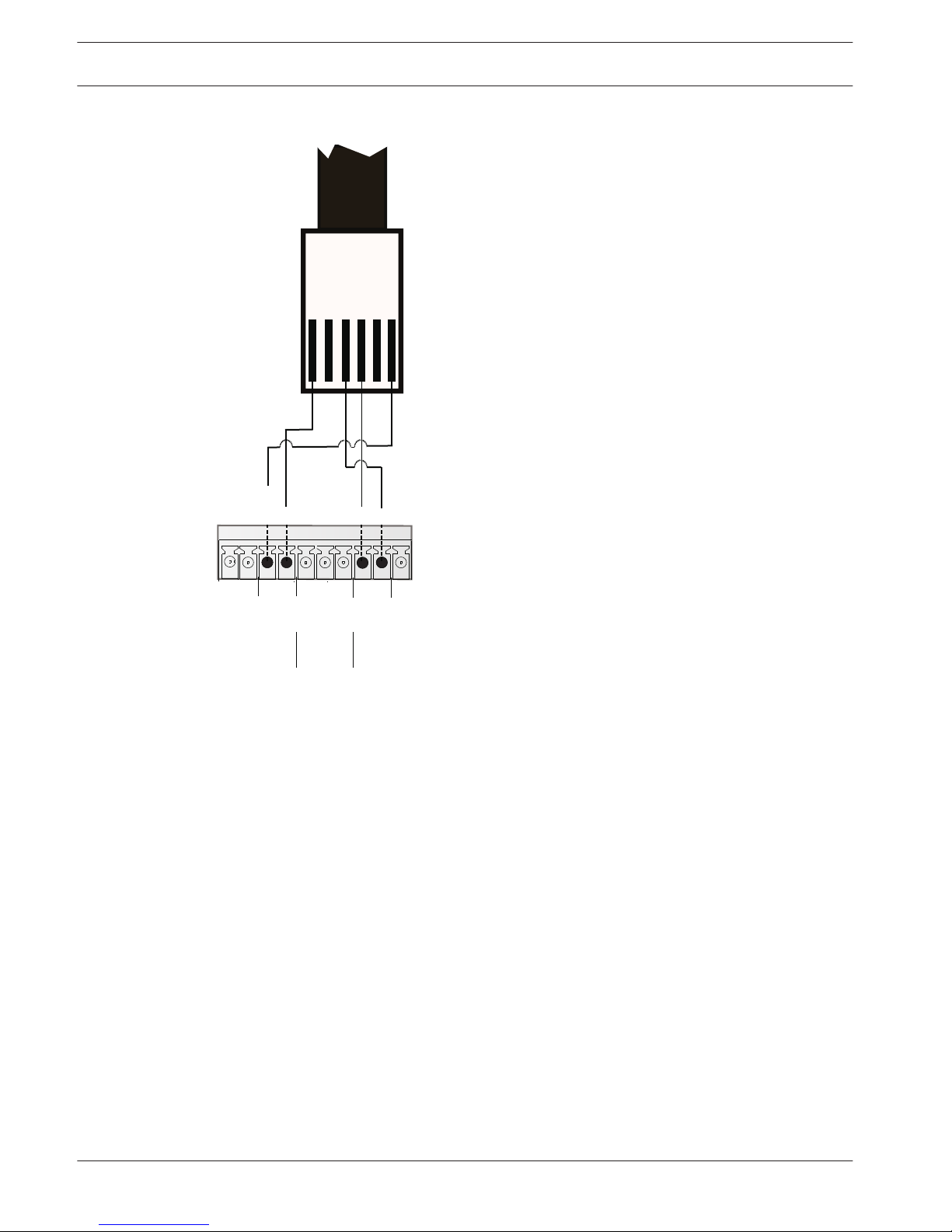
–
Or, connect the keyboard RJ11 wires to the Keyboard connector on the DIVAR back
panel as shown in the following figure.
5.3.2
5.3.3
5.4
DIVAR 3000/5000 Digital Video
Recorder
Hardware setup | en 29
Bosch Security Systems Operator Manual 2013.05 | 1.0 | DIVAR 3000/5000 Digital Video
Recorder
RS-485 KEYBOARD
po
wer to
keyboard
keyboard
con
trol
RJ11
+12V
Keyboard cable connector
G
G
+
_
G
G
+
_
G
+12V
CTRL
+12V
_
+
Figure 5.2: Keyboard connector
Specifications
–
Communication protocol: RS485
– Maximum signal voltage: ± 12 V
– Power supply: 11 - 12.6 VDC, maximum 400 mA
– Maximum cable length: 30 m (using standard 6-core telecom flat cable), or 1.5 km (using
Belden 8760 or equivalent in combination with the LTC 8557).
– Cable type: black (cross-over) cable (supplied with keyboard)
– Connector: RS485
Ethernet connection
The standard RJ-45 Ethernet socket is used to connect the unit directly to a PC or to a
network. To connect directly to a network hub or switch, use a straight-through network
cable. To connect directly to a PC, use a cross-over network cable. Consult with your local IT
personnel for the specific type of cable needed. The maximum cable length from node to node
is limited to 100 meters (300 feet).
Specifications
–
1000 Base-T IEEE 802.3ab compliant, 100Base-TX IEEE 802.3u Compliant, 10Base-T IEEE
802.3 Compliant
– IEEE 802.3 Compliant RGMII/MII
– DSP processing
5.5
30 en | Hardware setup
DIVAR 3000/5000 Digital Video
Recorder
2013.05 | 1.0 | DIVAR 3000/5000 Digital Video
Recorder
Operator Manual Bosch Security Systems
 Loading...