

Page 1
TriTech Ceiling Mount
PIR/Microwave Detector
DS9360
en Installation Guide
Page 2
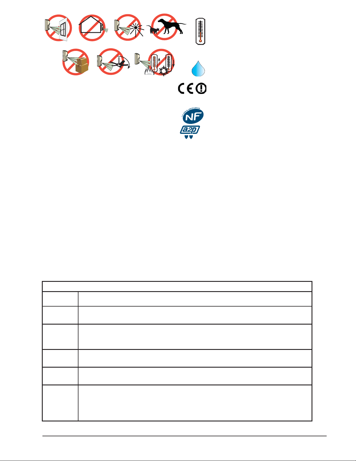
-40°C to +49°C
(-40°F to +120°F )
UL Listed
installations,
the temperature
range is 0°C to +49°C
(+32°F to +120°F)
0 - 95% Relative Humidity
(0 - 85% UL Installations)
Pour les
installations
certifi ées NFA2P,
Température de
fonctionnement
-10°C à +55°C
Changes or modifi cations not expressly approved
by Bosch Security Systems, Inc. can void the user’s
authority to operate the equipment.
UL
Perform Walk Test at least once a year.
Use only a Listed limited-power source.
The Listed control unit or a Listed burglary power
supply must provide 4 hours (32 mAh) of standby
power.
Install the unit in accordance with National
Electrical Code NFPA 70.
Adjust the microwave range control, if necessary, to
achieve maximum range.
SELV
Connect all wiring to a safety extra-low voltage (SELV) circuit only.
Ligue todas as cablagens apenas a um circuito de segurança de tensão extra baixa.
Conecte el cableado únicamente a un circuito de seguridad para voltajes muy bajos.
Alle Drähte sind ohne Ausnahme an Niederspannung anzuschließen.
Sluit alle bedrading uitsluitend aan op een circuit met een extra lage veiligheidsspanning.
Prenez soin de connecter tous les câbles à un circuit à très basse tension de sécurité (TBTS).
Collegare tutti i cavi esclusivamente a un circuito di sicurezza a bassissima tensione.
This product is intended for use in the following countries within the European Union and in other countries
outside of the European Union:
Austria, Belgium, Denmark, Finland, Greece, Luxembourg, Netherlands, Norway, Spain, Sweden, Italy
EN 50131-2-4 Grade 2
EN 50130-5 Environmental Class II
IP30 IK04 (EN 60529, EN 62262)
Certifi cat NF A2P 2820200006A0
2 boucliers NF324 - H58
Autosurveillance à l’ouverture
Immunité champ magnétique
Test sans masque de vision verticale
et sans immunité aux animaux
www.afnor.org
www.cnpp.com
Specifi cations
Dimensions
(HxDia)
Input
Power
Standby
Power
Alarm Relay Silent-operating Form “C” relay. Contacts rated <100 mA, 25 VDC, 2.5W <20 Ohm closed
Tamper Contacts rated at 28 VDC, 125 mA maximum, <1 Ohm. To be connected to a SELV (Safety
Compliance This device complies with Part 15 of the FCC Rules. Operation is subject to the following
För svensk installationsanvisning se www.boschsecurity.se.
3.5 in. x 5.25 in. (8.9 cm x 13.3 cm)
6.0 to 15.0 VDC; 8 mA standby, 60 mA in alarm with LEDs enabled. Use only an Approved
Limited Power Source.
There is no internal standby battery. Standby power must be provided by an Approved
Limited Power Source. Eight mAh required for each hour of standby time needed. For UL
Listed Requirements, 32 mAh standby current is required.
maximum for DC resistive loads.
Extra-Low Voltage) circuit only. Connect tamper circuit to a 24-hour protection circuit.
two conditions:
(1) this device may not cause harmful interference, and
(2) this device must accept any interference received, including interference that may
cause undesirable operation.
2 © 2015 Bosch Security Systems, Inc.
Page 3
1 Installation Considerations
re
Cover
Never install the detector in an environment that causes an alarm
condition in one technology. Good installations start with the LED off
when there is no target motion. It should never be left to operate with the
tri-color LED in a constant or intermittent green, yellow, or red condition.
NOTICE!
Microwave energy will pass through glass and most common
non-metallic construction walls.
Eliminate interference from nearby outside sources.
Point the unit away from outside traffi c (roads/alleys).
2 Mounting
Select a location likely to intercept an intruder moving beneath and across
the coverage pattern. Recommended mounting height range is 8 to 18 feet
(2.4 to 5.5 m).
The surface should be solid and vibration-free. (i.e. Drop tiles should be
secured if the area above the tiles is used as an air return for HVAC systems).
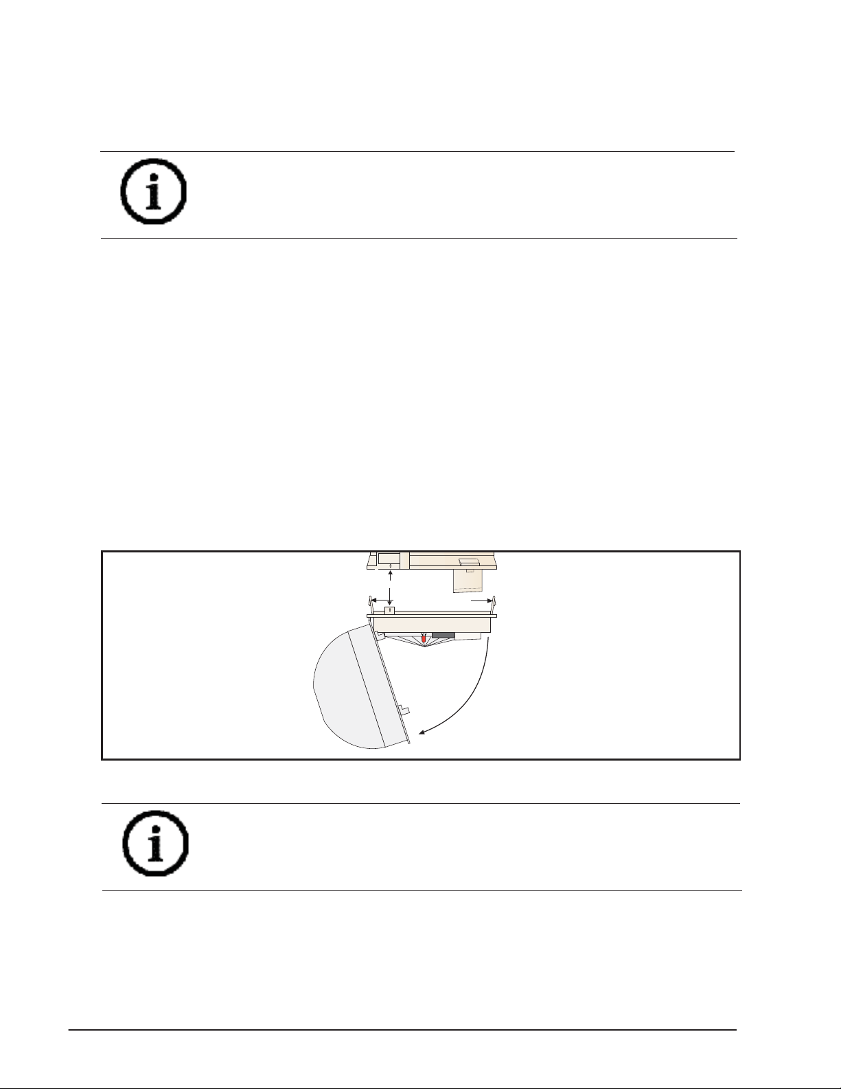
1. Remove the base from the enclosure by pressing the two enclosure
release tabs inward while lifting the enclosure away from the base.
Refer to Figure 2.1.
Base
Anti-vandal locking screw holes
Enclosure Release Tabs
Enclosu
The Cover remains
attached to the
Enclosure
Figure 2.1: Opening cover
NOTICE!
Slightly rock the enclosure side-to-side during removal to overcome the
friction caused by the base-to-enclosure terminal pins.
2. Open the cover by turning counterclockwise. One side of the cover will
remain attached to the base of the detector. Do not attempt to entirely
remove the cover. Refer to Figue 2.1.
3. Route wiring as necessary to the rear of the base and through the
center hole. Refer to Figure 2.2.
F.01U.263.664 | 05 | 2015.10 | 3
Page 4

NOTICE!
T
Be sure all wiring is de-energized before routing.
4. Firmly mount the base. Depending on local regulations, the base may
be directly surface mounted using anchors, mollies, or wing-nuts, or
may be mounted to standard 4-inch octagonal or square electrical
boxes.
NOTICE!
The DS9360 base will not completely cover a 4-inch square box. Where
aesthetics are important, a 4-inch octagonal box is recommended.
NOTICE!
Mounting to removable ceiling tiles is not recommended unless a
sandwich is made of the base, ceiling tile, and a back plate behind the
tile. Covers used for 4-inch octagonal and square boxes make a suitable
back plate (when used with bolts and wing nuts, as an example).
WIRE
TIE-DOWNS (2)
MOUNTING
SLOTS (4)
Figure 2.2: Mounting
3 Wiring
CAUTION!
Only apply power after all connections have been made and inspected.
Do not coil excess wiring inside detector.
AWG (0.8 mm) wire in the terminal strip.
REAR WIRE
ENTRANCE
Mounting Base
TERMINAL
INTERFACE
POWER
STRIP
18
PINS
Anti-vandal Screw Hole
Required for
EN50131
Installations
Wires
To
Cover
ALARM
LED
Top View of
TAMPER
LED and
LED Jumper
Sensitivity
Jumper
LED
OFF ON
I H
MIN
Microwave
Adjustment
Anti-vandal Screw Hole
Required for
EN50131
Installations
Use no smaller than #22
ROUBLE
-
+
+
-
Figure 3.1: Wiring to terminals
4 © 2015 Bosch Security Systems, Inc.
NO
C
NC
T
TR
T
Page 5

Terminals 1 (-) & 2 (+): Power contacts.
Terminals 3 (NO), 4 (C), & 5 (NC): Alarm relay contacts. Use terminals 4
& 5 for Normally Closed circuits. Do not use with capacitive or inductive
loads.
Terminals 6 (T) & 7 (T): Normally Closed tamper contacts.
Terminal 8 (TR): Solid state Trouble output. Shorts to ground (-) when the
detector is in a Trouble condition.
4 Coverage
• 360° by 60 ft. (18.3 m) diameter coverage when mounted on 8 to 18 ft
(2.4 to 5.5 m) high ceilings.
• The coverage pattern consists of 64 zones grouped into 16 barriers,
with one additional zone looking straight down from the unit
(sabotage). Each barrier is 30 ft (9.2 m) long and 4.4 ft. (1.3 m) wide
at 30 ft (9.2 m).
• The DS9360 comes with a choice of two optical modules. Refer to
Section 5.1 to determine the best module for on ceiling height.
30 ft
26 ft 20 ft 13 ft 7 ft 0 ft 7 ft 13 ft 20 ft 26 ft
9 m
8 m
6 m
4 m
2 m
0 m
2 m
4 m
6 m
8 m
9 m 30 ft
8 m6 m4 m2 m0 m2 m4 m6 m8 m
9 m
30 ft
30 ft
26 ft
≤5.5 m
20 ft
4.6 m
≥4.0 m
13 ft
7 ft
0 m
0 ft
7 ft
≤4.0 m
3.0 m
≥2.4 m
13 ft
20 ft
0 m
8 m6 m4 m2 m0 m2 m4 m6 m8 m
26 ft
9 m
9 m
AR13-18
AR8-13
≤18 ft
15 ft
≥13 ft
0 ft
≤13 ft
10 ft
≥8 ft
0 ft
9 m
5 Optical Module
5.1 Selecting the Optical Module
1. For ceilings between 8 and 13 ft. (2.4 and 4.0 m) from the fl oor, use
the optical module marked AR8-13. This marking can be found next to
the two optical module tabs.
2. For ceilings between 13 and 18 ft. (4.0 and 5.5 m) high, use the optical
module marked AR13-18.
3. To replace an optical module, push the optical module tabs towards
the center until the module snaps free of the circuit board. Holding the
new module by the tabs, snap the new module into place.
4. Replace the enclosure onto the base.
5. Close cover and turn clockwise to secure.
NOTICE!
Avoid fi ngerprints on the mirrored surfaces. Should the mirrored surfaces become soiled or otherwise marked, they can be cleaned using a
soft, clean cloth and any commonly available, mild window cleaner.
F.01U.263.664 | 05 | 2015.10 | 5
Page 6

432143125
D
E
F
I
TOP VIEW
M
5.2 Optical Module Masking
Peel-off masks are provided with the unit for each segment of the
optical module to allow for customized coverage, or to block out areas
of objects that may cause thermal disturbances. The mask is selfadhesive and pre-cut in the shape of the optical module.
The location of the zone to be masked depends on the position of the
detector. Therefore, determine the mirror surface to be masked before
removing the mirror from the detector.
To block out a particular zone or group of zones, peel off a section of
the mask that corresponds to the appropriate zone, and stick it on the
mirror segment. Before attempting any masking, be sure the chosen
mirror surface is the correct one.
NOTICE!
When attempting to remove any masking, many adhesives will either
destroy the mirror surface or leave enough residue behind to reduce
coverage performance.
SIDE VIEW
-4
M-3 M-2 M-1 E-1 E-2 E-3
5
N
E-4
M
L
AR8-13
A
P
O
K
J
B
C
D
E
F
G
H
I
AR8-13
O
N
M
L
K
A
P
J
B
H
Figure 8.1: Masking
When replacing the mirror, make sure it is facing the same direction as
before it was removed.
6 LED Operation
The detector uses a tri-color LED to indicate the various alarm and
supervision trouble conditions that may exist. See chart below.
LED CAUSE
C
G
Steady red Unit alarm
Tri-color Microwave activation
Steady green PIR activation
Flashing red Warm-up period after power-up (2 min)
Flashing red (4 pulse sequence) Replace unit
If the detector experiences a Microwave or PIR self-test failure, it is in
need of replacement.
6 © 2015 Bosch Security Systems, Inc.
Page 7

NOTICE!
During walk testing, the LED will light for the fi rst technology
(microwave or PIR) and then light red to indicate a detector alarm. The
LED will not indicate activation of the second technology by lighting its
color.
7 Feature Selection
7.1 LED On/Off Pins
The ON position allows operation of the tri-color LED. If LED indication
is not desired after setup and walk tests are completed, place in the OFF
position. The OFF position does not prevent the LED from indicating
supervision trouble conditions.
Sensitivity
Jumper
Figure 6.1: Selecting features
LED
Jumper
OFF
ON
LED
OFF ON
I H
I
H
7.2 PIR Sensitivity Selection Pins
For selection, place the plug across the pins marked I for Intermediate
mode or H for High mode.
• Intermediate Sensitivity (I): Tolerates environment extremes on this
setting, but requires the largest amount of intruder motion to achieve
an alarm.
• High Sensitivity (H): The recommended setting for most installations.
Use in locations where an intruder is expected to cover only a small
portion of the protected area. Tolerates normal environments on this
setting. The detector is shipped in High Sensitivity mode.
7.3 Microwave Adjustment
NOTICE!
It is important to wait 1 minute after removing/replacing the cover so
the microwave portion of the detector can settle, and to wait at least 5
seconds between the following walk testing procedures.
1. The tri-color LED should be off before walk testing.
2. Walk test across the pattern at the intended coverage’s farthest end.
Start walking from outside the intended protection area and observe
the tri-color LED. The edge of the microwave pattern is determined
by the fi rst tri-color, microwave activation of the LED (or the fi rst red
activation if the green PIR LED activates fi rst).
F.01U.263.664 | 05 | 2015.10 | 7
Page 8
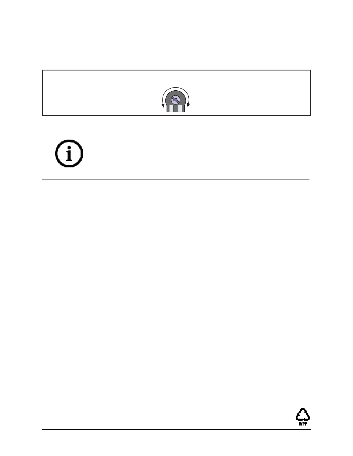
3. If adequate range can not be reached, increase the Microwave Range
Adjust slightly. Continue walk testing (waiting 1 minute after removing/
replacing the cover) and adjusting the range until the farthest edge of
desired coverage has been accurately placed.
4. Walk test the unit from all directions to determine all the detection
pattern boundaries.
Microwave
Adjustment
MIN
Figure 6.2: Adjusting microwave range
NOTICE!
Do not adjust the microwave range higher than required. Doing so
may cause the detector to catch movement outside of the intended
coverage pattern.
MAX
8 Supervision Features
The supervision features function as follows:
• PIR/Microwave: The complete circuit operation of these subsystems
is checked approximately every 6 hours. If the PIR or microwave
subsystem fails, the red LED will fl ash 4 times per cycle and the unit
should be replaced.
• Default: The detector will default to PIR technology protection if the
microwave subsystem fails.
9 Other Information
9.1 Anti-Vandal Screws for EN50131 Applications
After the cover has been installed and twisted into place, the entire
assembly can be secured together using the supplied anti-vandal screws.
The anit-vandal screws are required for EN50131 applications. Refer to the
Top View of Enclosure in Figure 2.2 for the location of the screw holes.
9.2 Maintenance
At least once a year, the range and coverage should be verifi ed. To ensure continual daily operation, the end user should be instructed to walk
through the far end of the coverage pattern. This ensures an alarm output
prior to arming the system.
Bosch Security Systems, Inc. product manufacturing dates
Use the serial number located on the product label and refer to the Bosch
Security Systems, Inc web site at: http://www.boschsecurity.com/datecodes/.
© 2015 Bosch Security Systems, Inc. 130 Perinton Parkway Fairport, NY 14450
 Loading...