

Bosch DS915 Installation Manual
DS915 Recess Mount Passive Mount Infrared
I
Intrusion Detector
General Information:
The DS915 is a semi-flush mount, Passive Infrared Intrusion Detector which is
designed to mount in a standard single gang electrical box or directly to a wall
using the supplied flush mount ring. It uses alternate polarity pulse count
processing, is internally pointable and uses "grooves-in" Fresnel lenses to
provide 6 different coverage patterns.
Input Power: 10 TO 15 VDC non polarized; 15 mA.
Standby Power: No internal standby battery. Unit is intended to be
connected to DC power sources capable of supplying standby power in
the event primary power fails. 15 mA-h required for each hour of standby
time needed.
Range: The standard Broad Coverage lens provides a 30 ft. (9 m) long by
38 ft. (12 m) wide pattern. Optional lenses are also available. The Broad Pet
avoidance lens provides the same coverage without look down zones.
Coverage Poinability:+2° to -12° Vertical; ±10° Horizontal. Each 2° of movement equals 1 ft. (.3 m) of pattern shift at 30 ft. (9 m).
Sensitivity: Adjustable for standard, intermediate and high sensitivity.
Alarm Relay: Normally Closed operation and protected by a 4.7 ohm
resistor in series with the relay contact. The reed relay contact is rated at
28 VDC, 125 mA maximum for DC resistive loads.
Temperature: The storage and operating range is -20°F to +120°F (-29°C
to +49°C). For UL Listed Requirements, the temperature range is +32°F to
+120°F (0°C to +49°C).
Options: TC6000 Test Cord, OLC91-3* Dual Corridor lens, OLW91-3* Dense
Wide Angle lens, OLP91-3* Pet Avoidance lens, OLR91-3* Long Range
Barrier lens and OLB91 Barrier lens. *Shipped in packages of three.
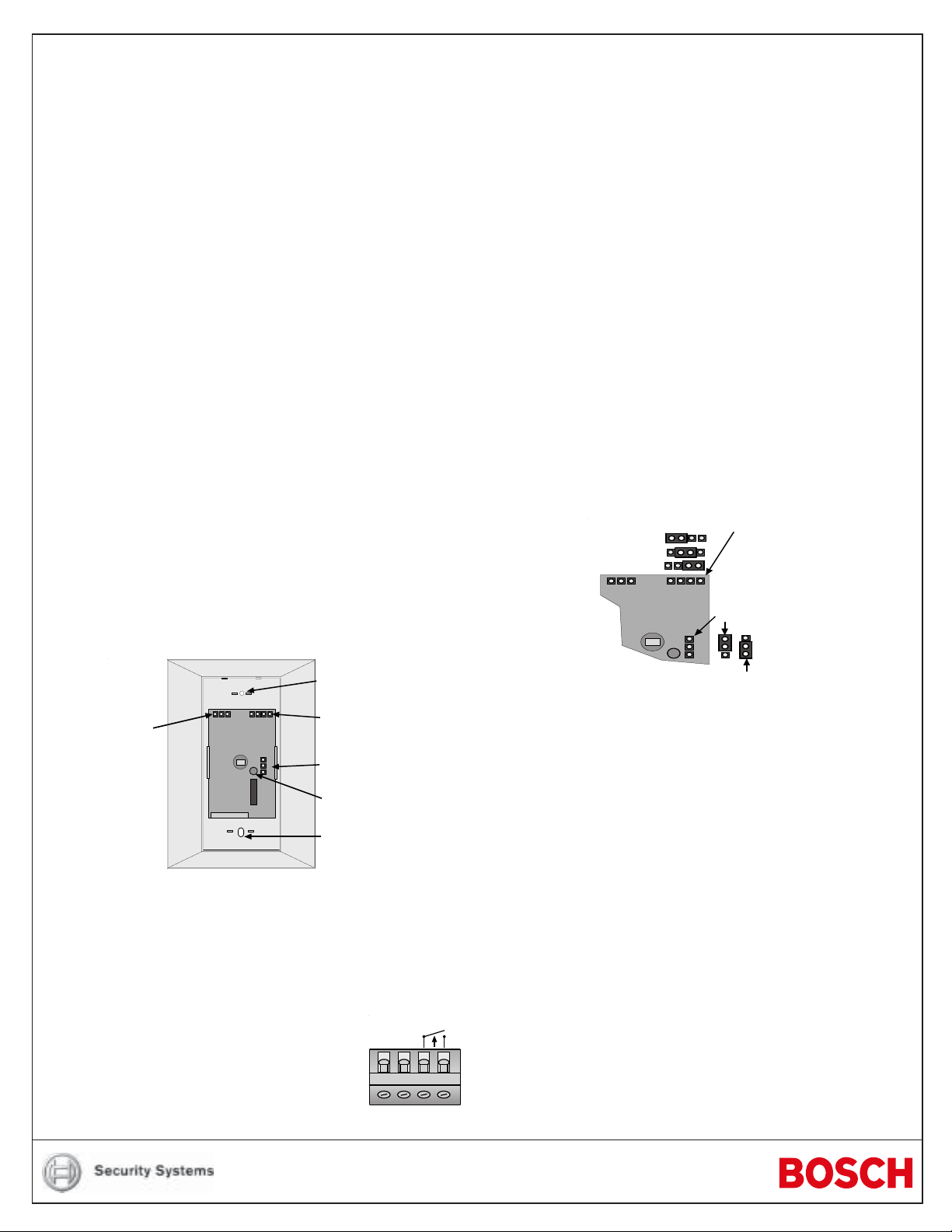
Select Mounting Location:
Mounting Hole
Background
Noise
Voltage
Connector
H I S
NV
D
E
• Select a location that is most likely to intercept an intruder moving across the
coverage pattern. The DS915 is designed to mount to a standard single
gang electrical box (not supplied). Mount the box and pull wiring to the box
before installing the detector.
• Review pattern side views to estimate best mounting height. Recommended
mounting height is 6.5 ft. (2 m). The mounting range is from 3 ft. to 8 ft. (1 m
to 2.5 m).
• Remove the front cover by pulling out from the bottom.
• Connect wiring as shown.
CAUTION: Only apply power after all connections have
been made and inspected.
Sensitivity
Jumper
LED Enable
Test/Alarm LED
Mounting Hole
ALARM10-15
VDC
1234
• Terminal 1 & 2 power limits are 10 to 15 VDC measured at the terminals,
polarity is not important. Use no smaller than #22 AWG ( .8 mm) wire pair,
500 ft. (150 m.) max. between the unit and the power source.
• Connect a Normally Closed burglar alarm loop to terminals 3 and 4. A detector alarm will cause an open circuit.
NOTE: Do not coil excess wiring inside unit.
• Mount the detector into the single gang box (if used) using the supplied
screws.
Recess Mounting without an electrical box
The DS915 may be recess mounted without the use of a single gang box by
using the supplied recess mount ring.
• Using the recess mount ring as a template, prepare an opening 1-7/8"
(48 mm) wide by 2-3/4" (60 mm) wide in the mounting surface.
• Route wiring through opening and ring.
• Place the ring over the opening and bend the support tabs into the opening
and around the mounting surface so that the ring fits snug against the wall.
• Connect wiring.
• Mount the detector to the ring using the supplied screws.
Select Sensitivity:
The DS915 permits selection of response sensitivity modes depending on the
type of coverage desired, and the installation environment.
Sensistivity Jumper
H ig h
ntermediate
S
tandard
NV
H I S
LED Jumper
D
D
E
Enabled (on)
isabled (off)
Standard: Tolerates most environment extremes on this setting, but requires
the largest amount of intruder motion to achieve an alarm. Standard Sensitivity
is not recommended for use with barrier, long range barrier or dual corridor
coverages.
Intermediate: Recommended setting for most installations. Use in locations
where an intruder is only expected to cover a small portion of the protected
area. Tolerates nor mal environments on this setting.
High: Fast response to intruder signals. For use only in quiet environments
where thermal and illumination transients are not anticipated.
In the event the Sensitivity Jumper is missing, the unit will default to the intermediate setting.
LED Disable: If viewing the operation of the LED is not required after setup
and walk testing are completed, remove the lens holder assembly and place
the LED Jumper across the center and top pin (marked D). If the Jumper is
missing, the LED is disabled.
Set up and walk testing:
• Choose the proper coverage pattern. If it's necessary to replace the lens,
perform the following.
- Remove the lens holder assembly by sliding it down to its lowest point and
pulling it out from the top.
- While facing the rear of the lens holder, gently push down and inwards on
the top ledge of the window frame until the frame pops out of the top track.
Then push up on the bottom ledge until the frame pops out of the bottom track.
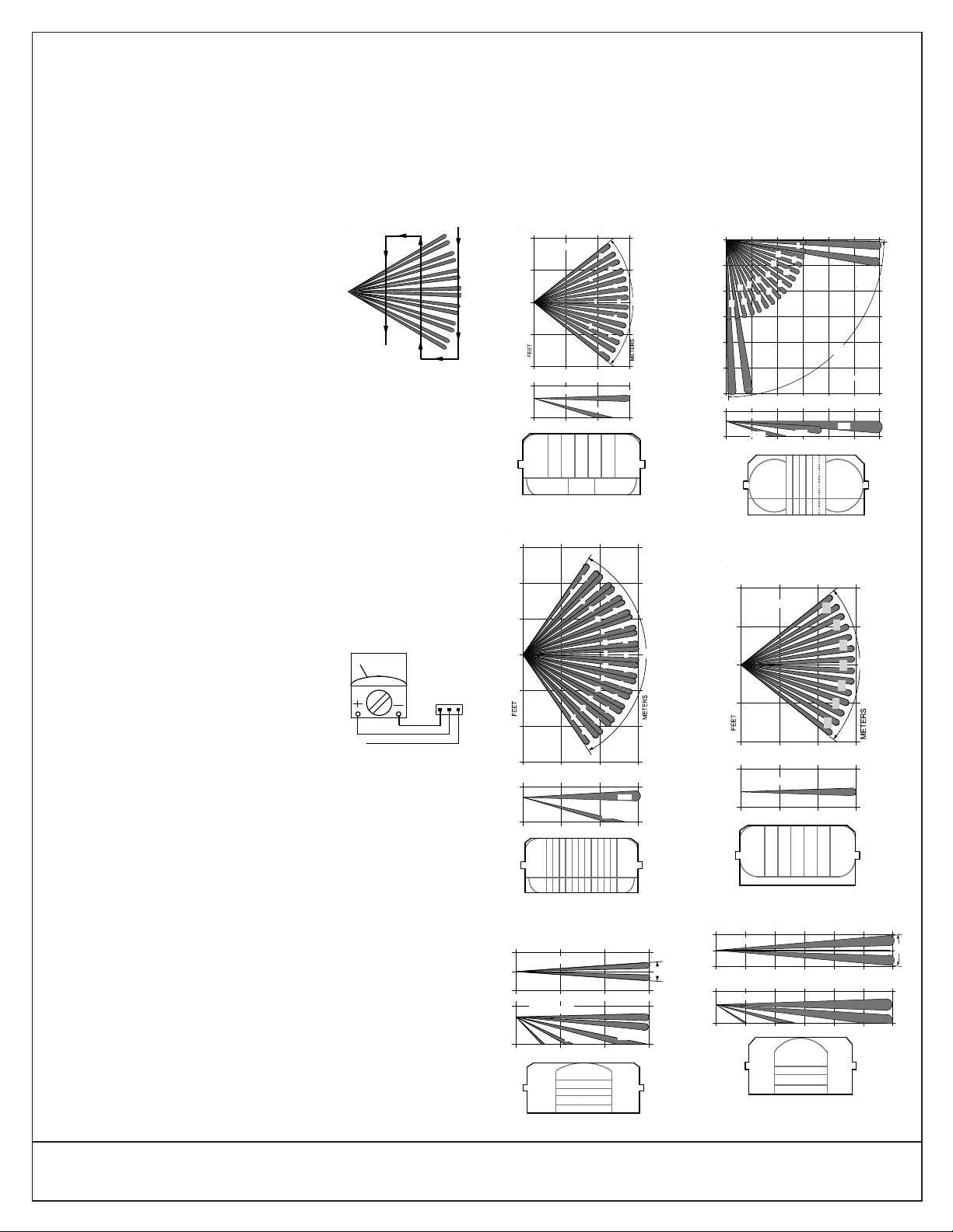
DUAL CORRIDOR
OLC91
A
B
C
D
EFGH
J
K
LMNO
I
P
FEET
A, J
0 102030405060
B - I
K - P
SIDE VIEW
0
10
20
50
60
0 102030405060
30
40
C
D
E
F
G
H
P
K
L
M
N
O
METERS
369121518
3
6
9
12
15
18
TOP VIEW
A
89°
10
J
I
B
0
10
20
10
20
10 20 30
0
10 20 300
36 9
3
3
0
10
4
FEET
0
SIDE VIEW
TOP VIEW
METERS
77°
ABCDE GF
PET
AVOIDANCE OLP91
A
B
C
D
E
F
G
- Rotate the frame left or right until the lens clears the tracks.
- Remove lens and replace with appropriate lens. Install with smooth side
of lens facing out; rough side inward. The clipped corners should go on
the top of the unit. Bend two tabs inward to hold lens in place.
- To replace the window, center the window in the cover and slip the
bottom of both the frame and lens into the bottom track.
- Carefully push down and forward on the top frame ledge until the frame
snaps into the top track. Center the window so that the tracks are
between the frame stops.
- Replace the lens holder and snap into place.
• Apply power to the unit.
• Wait at least two minutes, after applying power, to
start walk tests.
NOTE: Walk testing should be done across the cov-
erage pattern.
• The edge of the coverage is determined by activation of the alarm LED.
• Walk test the unit from both directions to determine the boundaries.
If the rated range can not be achieved, try angling the coverage pattern up or
down to ensure the pattern is not aimed too high or low.
The angle of the pattern may be vertically positioned between -12° and +2° by
sliding the lens holder up or down. A good starting angle when the detector is
mounted at 6.5 ft. (2 m) is -7° for the standard, wide angle, and barrier
coverages, -4° for the dual corridor and -2° for the long range coverage.
NOTE: The pattern may also be moved ±10° horizontally by rotating the
window left or right.
Final Tests:
NOTE: Meter readings are very important in determining background distur-
• Connect a 20,000 ohm/volt (or greater) DC VOM to
• The base reference level for reading background
Voltage changes greater than 0.75 VDC from the reference level are desirable
for good catch performance. If changes are less than plus or minus 0.75 VDC,
the device may fail to respond at this distance if the temperature difference
between the intruder and the background is very small. Try aiming the unit up
and down to maximize the voltage change during walk tests.
• Turn on all heating and cooling sources that would normally be in operation
Other Information:
Maintenance: At least once a year the range and coverage should be check ed
in accordance with the section Set Up and Walk Testing. To ensure continued
daily operation, the end user should be instructed to walk through the far end
of the coverage pattern to assure an alarm output prior to arming the system.
© 2004 Bosch Security Systems
130 Perinton Parkway, Fairport, New York, USA 14450-9199
Customer Service: (800) 289-0096; Technical Suppor t: (888) 886-6189
bance levels and catch margin sensitivity.
the Background Noise Voltage connector pins as
shown. Set meter scale for about 5 VDC. (Use of
the TC6000 is recommended, but is not essential for
meter use.)
noise or target voltages is approximately 2.0 VDC.
TC6000
Installations in quiet environments, therefore, will result in a steady meter
reading between 1.8 and 2.2 VDC.
during times of protection. Stand awa y from the unit and outside the coverage
pattern, then monitor the background noise for at least three minutes. The
DS915 readings should not deviate from the reference level more than
±0.2 VDC. For readings outside these limits, eliminate the cause or adjust
the unit slightly.
WHITE
RED
BLACK
Pet Lens Considerations: The Pet Lens is intended to provide protection in
installations where pets are allowed to move about freely.
• Because the unit will be installed lower than normal, be sure to position the
unit so that it has a clear line-of-sight across the room.
• Adjust the Lens Holder Assembly for a 0° vertical angle.
• To provide an accurate safety margin, install the unit no lower than twice
the height of the pet.
• Make sure the field of view is free of all furniture or other objects upon
which the pet could climb or jump, resulting in an unwanted alarm.
Coverage Patterns:
369
0 METERS
20
TOP VIEW
10
0
10
20
10
0
10
SIDE VIEW
6
FEET
0
10
ABCDEGF
I
H
STANDARD
OLS91
METERS
0
30
20
10
10
20
30
10
5
0
5
10
0
36
TOP VIEW
0
0
SIDE VIEW
0
0 102030
FEET
M
Z
Y
O
N
A
10 30
369
Z
115° WIDE ANGLE
OLW91
ME T ERS
0
36
TOP VIEW
SIDE VIEW
E
D
31°
50°
FEET
10
A
B
C
D
E
BARRIER
OLB91
6
A
B
3
H
C
D
I
77°
E
J
F
3
G
6
30
20
A - G
0°
H - J
14.5°
30
20
J
9
9
L
X
W
Q
P
B
20
6
K
J
3
I
V
H
U
T
115°
G
S
F
R
E
3
D
C
6
9
0°
A - M
N - Z
14.5°
AM
N
369121518
METERS
5
9
9°
3
0°
A
B
5°
14.3°
C
30
20
TOP VIEW
0
5
FEET
0 102030405060
10
SIDE VIEW
D
C
FEET
0 102030405060
181512963
A
B
A
B
C
D
LONG RANGE
BARRIER OLR91
9°
02/04
DS915 Installation Instructions
P/N: 22489G Page 2
 Loading...