

Bosch DS860 Installation Instructions Manual
Installation Instructions
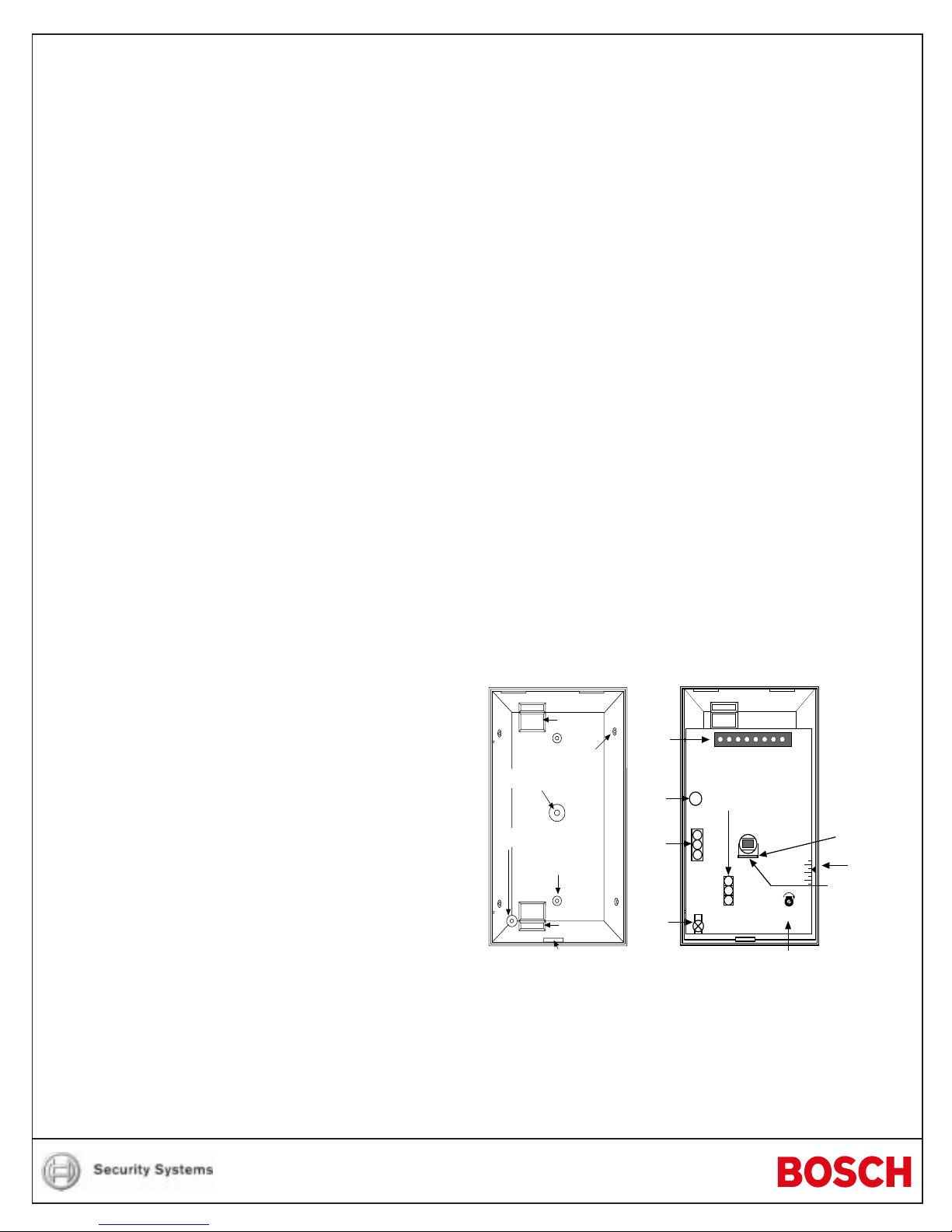
Vertical
Adjust
Screw
Tri-color
LED
Terminal
Strip
LED
On/Off
Pins
MW
0°
- 4°
- 8°
On
Off
Microwave
Range Adjust
PIR
Sensitivity
Selec tio n P in s
Vertic al Adjust
Scale
Look Down Lens
MIN MAX
Face of Lens
(masking area)
Corner Mount
Knockout (4)
Surface Mount
Knockout (2)
Wire
Entrances
Bracket Mount
Knockout
Vertical Adjust
Screw Mount
Cover Tab and
Locking Screw Hole
Wire
Entrances
for the DS860 Series
TriTech Microwave/PIR Intrusion Detectors
1.0 Specifications
• Dimensions (HxWxD): 5 in. x 2.8 in. x 2.2 in.
(12.7 cm x 7.1 cm x 5.6 cm)
• Input Power: 9 to 15 VDC, 16 mA DC nominal
(up to 48 mA DC during walk testing or
trouble conditions). Use only an
Approved Limited Power Source.
• Standby Power: No internal standby battery.
Standby power must be provided by
an Approved Limited Power Source.
Sixteen mAh required for each hour of
standby time needed.
Requirements, four hours (64 mAh)
minimum are required.
• Alarm Relay: Silent operating Normally Closed
reed relay. Contacts rated 3 watts,
125 mA, 28 VDC maximum for DC
resistive loads; and protected by a
4.7 ohm, 0.5 watt resistor in the
common "C" leg of the relay. To be
connected to a SELV (Safety Extra-Low
Voltage) circuit only. Do not use with
capacitive or inductive loads.
• Temperature Range: -40°F to +120°F (-40°C to +49°C).
For UL Listed Requirements, the
temperature range is +32°F to +120°F
(0°C to +49°C).
• Microwave Frequency:
DS860: 10.525 GHz (UL Listed)
DS860A: 10.687 GHz (Export only, not UL
Listed)
DS860B: 9.9 GHz (Export only, not UL Listed))
• Coverage:
Broad (standard): 60 ft. by 60 ft. (18 m by 18 m)
Long Range (optional): 100 ft. by 10 ft. (30 m by 3 m)
• Internal Pointability: +2° to –10° Vertical, ±10° Horizontal.
• Tamper: Normally Closed (with cover on).
Contacts rated at 28 VDC, 125 mA
max. To be connected to a SELV
(Safety Extra-Low Voltage) circuit
only. Connect tamper circuit to 24-hour
protection circuit.
• Options: B328 Gimbal Mount Bracket, B335
Low Profile Swivel Mount Bracket,
B338 Ceiling Mount Bracket, OLR92
Long Range Barrier Lens
NOTE: Use of a bracket may reduce range and increase dead
zone areas.
• U.S. Patent Numbers: Protected under one or more of the
following U.S. Patent Numbers: #4,660,024, #4,764,755,
#5,077,548, #5,208,567, #5,262,783, and #5,450,062. Other
patents pending.
• Compliance: This device complies with Part 15 of the FCC
Rules and with RSS-210 of Industry and Science Canada.
Operation is subject to the following two conditions:
For UL Listed
(1) this device may not cause harmful interference, and
(2) this device must accept any interference received,
including interference that may cause undesirable
operation.
Changes or modifications not expressly approved by Bosch
Security Systems can void the user’s authority to operate the
equipment.
2.0 Installation Considerations
NOTE: The DS860 is not recommended for installations
containing pets or small animals. Use the DS820 or
DS835 for such installations.
• Never install the detector in an environment that causes an
alarm condition in one technology. Good installations start with
the LED OFF when there is no target motion. It should never be
left to operate with the tri-color LED in a constant or intermittent
green, yellow, or red condition.
• Point the unit away from outside traffic (roads/alleys).
NOTE: Microwave energy will pass through glass and most
common non-metallic construction walls.
• Avoid installations where rotating machines (e.g. ceiling fans)
are normally in operation within the coverage pattern. Point the
unit away from glass exposed to the outdoors and objects that
may change temperature rapidly.
NOTE: The PIR detector will react to objects rapidly changing
temperature within its field-of-view.
• Eliminate interference from nearby outside sources.
3.0 Mounting
• Select a location likely to intercept an intruder moving across
the coverage pattern. The surface should be solid and
vibration-free. Mounting height range is 6 to 8 ft. (1.8 to
2.4 m). Recommended mounting height is 7.5 ft. (2.3 m).
• Remove the cover. Insert a flathead screwdriver into the locking
tab hole at the bottom front of the detector. Pull the cover up
and forward.
• Remove the circuit board from the base. Loosen the Vertical
Adjust Screw and slide the circuit board down, then out.
• Break away the appropriate thin-wall wire entrance and
mounting hole coverings in the base.
• Using the base as a template and aligning it so that the
detector will be mounted with the terminal block at the top and
the PIR lens at the bottom, mark the location of the mounting
holes on the mounting surface. Pre-start the mounting screws.
• Route wiring as necessary. Route to the rear of the base and
through the wire entrance. Make sure all wiring is unpowered
before routing.
• Securely attach the base to the mounting surface.
• Return the circuit board to the base and tighten the Vertical
Adjust Screw.
4.0 Wiring
Only apply power after all connections have been
made and inspected. Do not coil excess wiring
CAUTION
inside detector.
NOTE: Input power must use only an Approved Limited Power
Source. Alarm and Tamper Contacts to be connected to a
SELV (Safety Extra-Low Voltage) circuit only.
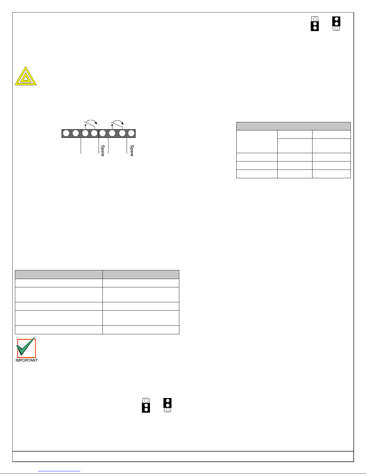
Alarm
1234
–
+CNC
9-15 VDC
Input
Alarm
Relay
Tamper
5678
SP T SPT
Tamper
• Terminals 1 (–) & 2 (+): Voltage limits are 9 to 15 VDC. Use no
smaller than #22 AWG (0.8 mm) wire pair between the detector
and the power source.
• Terminals 3 & 4: Alarm relay (reed) contacts rated 3 watts,
125 mA, 28 VDC maximum for DC resistive loads and
protected by a 4.7 ohm, 0.5 watt resistor.
NOTE: Do not use with capacitive or inductive loads.
• Terminals 5 and 8: Spare.
• Terminals 6 & 7: Tamper contacts rated at 28 VDC, 125 mA.
NOTE: Plug the wire entrance hole with the foam plug provided
after all wiring connections have been made.
5.0 LED Operation
The detector uses a tri-color LED to indicate the various alarm and
supervision trouble conditions that may exist. See chart below.
LED Cause
Steady red Unit alarm
Steady yellow
Steady green PIR activation (walk test)
Flashing red
Flashing red (4 pulse sequence) Replace Unit
If the detector experiences a Microwave or PIR
self-test failure, it is in need of replacement.
NOTE: During walk testing, the LED will light for the first
technology (microwave or PIR) and then light red to
indicate a detector alarm. The LED will not indicate
activation of the second technology by lighting its color.
6.0 Feature Selection
6.1 LED On/Off Pins
The ON position allows operation of the tri-color LED. If LED
indication is not desired after setup and walk tests are completed,
place in the OFF position. The OFF position does not prevent the
LED from indicating supervision trouble conditions.
Microwave activation
(walk test)
Warm-up period
after power-up
On
Off
6.2 PIR Sensitivity Selection Pins
For selection, place the plug across the pins
STD
INT
marked STD for Standard or INT for
Intermediate mode.
• Standard Sensitivity: The recommended setting for maximum
false alarm immunity. Tolerates environmental extremes on
this setting.
• Intermediate Sensitivity: The recommended setting for any
location where an intruder is expected to cover only a small
portion of the protected area. Tolerates normal environments
on this setting. This setting will improve your intruder catch
performance.
7.0 Set-up and Walk Tests
Select the vertical starting angle from this chart:
To adjust the
vertical starting
angle for the
desired
mounting height
and range,
loosen the
vertical adjust
screw and slide
Mounting
Height
6.5 ft. (2 m) -4° -2°
7.5 ft. (2.3 m) -5° -3°
8.0 ft. (2.4 m) -6° -3°
the board up, to
point the angle down. Note the settings on the vertical adjust scale.
• Place the LED plug in the ON position and replace the cover.
7.1 Establishing PIR Pattern Coverage
• Turn the Microwave range adjust to minimum.
• Replace the cover and snap it into place. This will close the
tamper switch.
• Wait two minutes minimum after applying power to start walk
tests.
NOTE: During the warm-up period, the tri-color LED will flash red
until the unit has stabilized (approximately 1 to 2 minutes)
and has seen no movement for two seconds. When the
tri-color LED stops flashing, the detector is ready to be
tested. With no motion in the protection area, the tri-color
LED should be OFF. If the LED is on, re-check the
protection area for disturbances affecting the microwave
or PIR technologies.
• Walk test across the pattern at its farthest edge, then several
times closer to the detector. Start walking from outside of the
intended protection area, and observe the tri-color LED. The
edge of the pattern is determined by the first green, PIR
activation of the LED (or the first red activation if the yellow
microwave LED activates first).
• Walk test from the opposite direction to determine both
boundaries. The center of the pattern should be pointed
toward the center of the intended protection area.
NOTE: The pattern may be moved ±10° horizontally by rotating the
lens window left or right.
• Slowly bring your arm up and into the pattern to mark the lower
boundary on PIR alarm. Perform this task at 10 to 20 ft. (3 to 6
m) from the unit. Repeat from above for the upper boundary.
The center of the pattern should not be tilted upward.
DS860
Broad Long Range
60 ft.
(18 m)
100 ft.
(30 m)
Page 2 © 2004 Bosch Security Systems DS860 Series Installation Instructions
 Loading...