

Bosch DS840, DS825, DS840T, DS825T Installation Instructions Manual
Installation Instructions
DS825, DS825T, DS840, DS840T
TriTech PIR/Microwave Intrusion Detectors
1.0 General Information
The DS825 Series and DS840 Series are microprocessor-based
TriTech Passive Infrared/Microwave Intrusion Detectors that provide
immunity to false alarms caused by pets [a dog up to 100 lbs.
(45 kg) or up to 10 cats, and other small animals such as birds
and rodents]. Patented Passive Infrared and Microwave signal
processing provides excellent catch performance with freedom
from false alarms.
2.0 Specifications
• Input Power: 6 to 15 VDC, 15 mA DC nominal (up to
35 mA DC during walk testing).
• Standby Power: No internal standby battery . Connect to
DC power sources capable of supplying
standby power. For each hour of
standby time needed, 15 mAh are
required. For UL Listed Requirements,
four hours (60 mAh) are required.
• Alarm Relay: Silent operating Normally Closed reed
relay. Contacts rated 3 W, 125 mA,
28 VDC maximum for DC resistive
loads; and protected by a 4.7 Ω,1/2 W
resistor in the common “C” leg of the
relay. Do not use with capacitive or
inductive loads.
• Temperature: -40°F to +120°F (-40°C to +49°C). For
UL Certificated Installations, the
temperature range is +32°F to +120°F
(0°C to +49°C).
• Microwave Frequency:
DS825(T)/DS840(T): 10.525 GHz (UL Listed)
DS825TA/DS840TA: 10.687 GHz (Export only, not UL Listed)
DS825TB/DS840TB: 9.9 GHz (Export only, not UL Listed)
• Coverage:
DS825 Series: 25 ft. x 25 ft. (8 m x 8 m)
DS840 Series: 40 ft. x 40 ft. (12 m x 12 m)
• Internal Pointability: +1° to –18° Vertical.
• Optional Tamper: The DS825T, DS825TA, DS825TB,
DS840T, DS840TA, and DS840TB
have a Normally Closed (with cover on)
tamper switch. Contacts rated at
28 VDC, 125 mA max. Connect the
tamper circuit to a 24-hour protection
circuit.
• Options: B335 Low Profile Swivel Mount Bracket
and B338 Ceiling Mount Bracket. (The
use of brackets may reduce range and
increase dead zone areas.)
• Reading Bosch Security Systems, Inc. Product Date Codes
For Product Date Code information, refer to the Bosch Security
Systems, Inc. Web site at: http://www.boschsecurity.com/datecodes/
• Compliance: This device complies with Part 15 of the FCC
Rules and with RSS-210 of Industry and Science Canada.
Operation is subject to the following two conditions:
(1) this device may not cause harmful
interference, and (2) this device must accept any
interference received, including interference that may cause
undesirable operation.
Changes or modifications not expressly approved by Bosch Security
Systems can void the user's authority to operate the equipment.
3.0 Mounting
3.1 Mounting Considerations
• Never install the detector in an environment that causes a constant
alarm in one technology; it should never be left to operate with
the tri-color LED in a constant green, yellow, or red condition. A
detector with one technology in constant alarm, will cause an
alarm output whenever the other technology alarms. Good
installations start with the LED OFF when there is no target motion.
The best installations will have background noise voltages below
recommended limits.
• Point the unit away from outside traffic (e.g. roads, alleys, and
parking lots).
NOTE: Microwave energy will pass through glass and most
common non-metallic construction walls.
• Avoid direct or indirect sunlight.
• Point the unit away from glass exposed to the outdoors and objects
that may change temperature rapidly.
NOTE: The PIR detector will react to objects rapidly changing
temperature within its field-of-view.
• Eliminate interference from nearby outside sources.
• Avoid installations where rotating machines (e.g. ceiling fans) are
normally in operation within the coverage pattern.
• Select a location likely to intercept an intruder moving across
the coverage pattern.
• The surface should be solid and vibration-free.
• Mounting height range is 6 to 8 ft. (1.8 to 2.4 m). The
recommended height is 7.5 ft. (2.3 m). Mounting height for Pet
Applications is 6.5 ft. (2 meters).
3.2 Mounting the Detector
• Remove the cover by inserting a thin flathead screwdriver into
the locking tab hole at the bottom front of the detector, pressing
in, and pulling the cover up and forward.
NOTE: Mount the unit with the terminal block up.
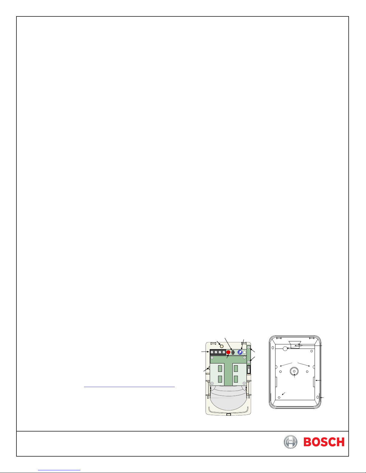
• Remove the circuit board from the base by pulling outward slightly
on one of the Circuit Board Locking Tabs (see Figure A).
LED Jumper
Cable Knockout
Ter minal
Block
Circuit Board
Locking Tab
(One on
Each Side)
• Remove the mirror.
Microwave
Adjustment
Tamper
LED
Mirror
Assembly
Terminal s
Retainer Tabs (2)
Bracket Mounting
Rear enclosure and mounting holes
Figure A - Location of Features
Circuit Board
Hole
Surface
Mounting
Holes (4)
Wiring
Knockouts
Mirror
Tracks (2)
Corner
Mounting
Holes (2)
• Break away the Cable Knockout wire entrance.
• Open two holes for surface or corner mounting (See Figure A).
• Mark the location for the mounting screws.
- Use the enclosure as a template.
- Pre-start the mounting screws.
• Route wiring as necessary. Route to the rear of the base and
through the wire entrance. Make sure all wiring is unpowered
before routing.
• Securely attach the base to the mounting surface.
• Return the circuit board to the base.
• Install the mirror.
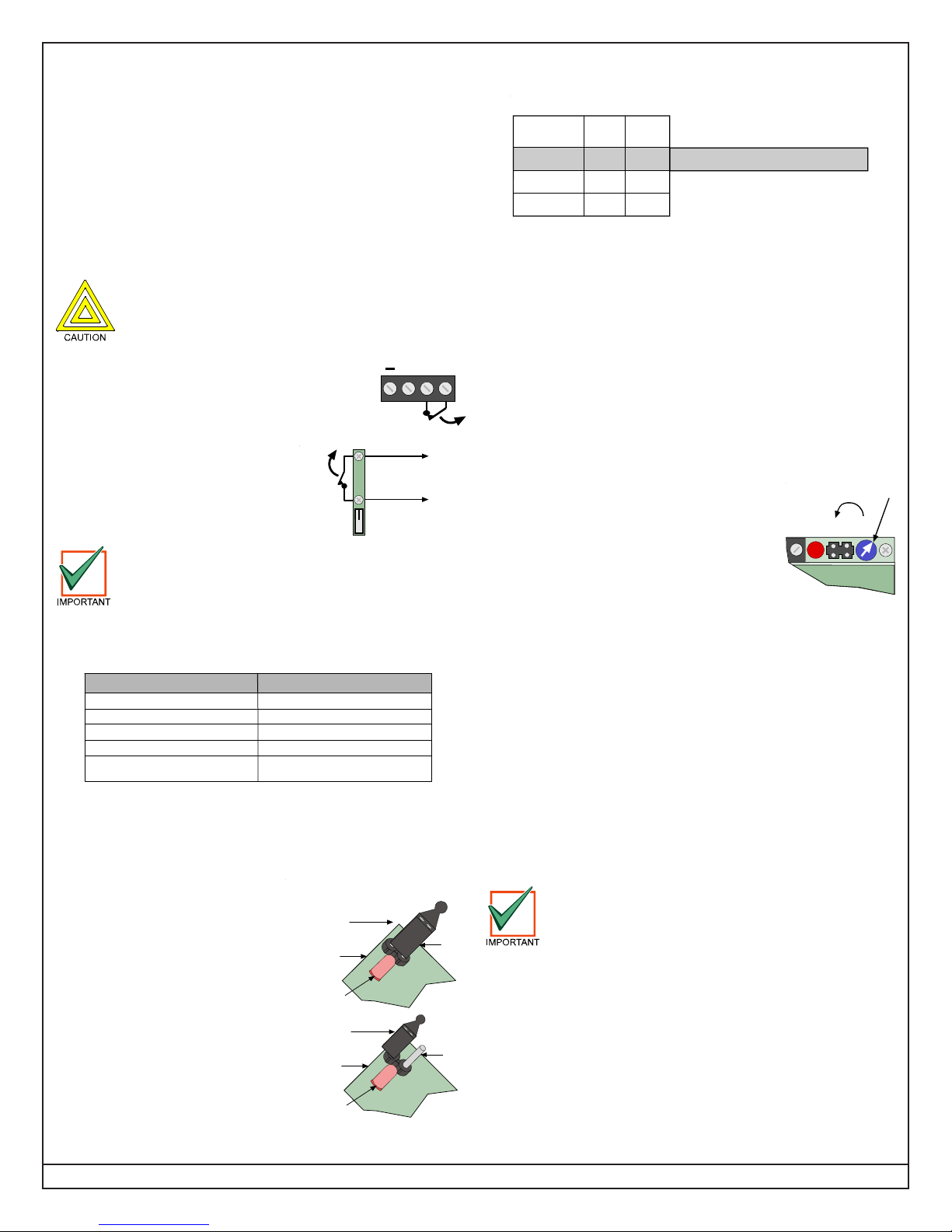
4.0 Wiring
Apply power ONLY after all connections have been
made and inspected. Do NOT coil excess wiring
inside the detector.
• Terminals (–) & (+): Power limits are 6 to 15
VDC. Use no smaller than #22 AWG (0.8 mm)
+
NC C
wire pair between the detector and the power
source.
• Terminals C & NC: Alarm relay (reed) contacts.
Do not use with capacitive or inductive loads.
• Tamper contacts: "T" Models only.
Cover
Off
Connect to a 24-hour
Protection Circuit
Alarm
Plug the wire entrance hole with the foam plug
provided after all wiring connections have been made.
6.0 LED Operation
The detector uses a tricolor LED to indicate the various alarm and
supervision trouble conditions that may exist. See the following chart:
LED
Steady red
Steady yellow
Steady green
Flashing red
Flashing red (4 pulse sequence)
Microwave activation (walk test)
Warmup period after power-up
If the detector experiences a Microwave or PIR self-test failure, it is in
need of replacement.
During walk testing, the LED will light for the first technology
(microwave or PIR) and then light red to indicate a detector alarm.
The LED will not indicate activation of the second technology by
lighting its color.
7.0 Feature Selection
• LED On/Off Pins: Placing the
jumper across the LED selection
pins allows operation of the
tricolor LED. If the tricolor LED
indication is not desired after
setup and walk tests are
completed, move the jumper from
across the LED selection pins.
Moving the jumper to the OFF
position does not prevent the
tricolor LED from indicating a
supervision trouble condition.
Cause
Unit alarm
PIR activation (walk test)
Microwave or PIR failure -
Replace Unit
LED ON/OFF JUMPER PLACEMENTS
Program Plug
in the
ON Position
Edge of
Circuit Board
LED
Program Plug
in the
OFF Position
Edge of
Circuit Board
LED
LED
Pins
LED
Pins
8.0 Setup and Walk Tests
• Select the vertical starting angle from the chart.
Broad Coverage Mirror
Mounting
Height
6.5 (2.0)
7.5 (2.3)
8.5 (2.6)
Height and desired Range
listed in feet (meters)
• The angle adjust markings are on the mirror. Slide the mirror
forward or back until the angle hash marks are in-line with the
markers on each side of the frame.
NOTE: See Section 11.0 for Pet Applications.
• Place the LED Jumper in the ON position.
• Wait at least two minutes, after applying power, to start walk
tests.
NOTE: During the warm-up period, the tricolor LED will flash red until
the unit has stabilized (approximately one to two minutes) and
has seen no movement for two seconds. When the LED stops
flashing, the detector is ready to be tested. With no motion in
the protection area, the LED should be OFF. If the LED is on,
recheck the protection area for
disturbances affecting the microwave
(yellow) or PIR (green) technologies.
Establishing PIR Pattern Coverage
• Turn the Microwave range adjust to minimum
and replace the cover.
• Walk test across the pattern at its farthest edge,
then several times closer to the detector. Start
walking from outside of the intended protection area, and observe
the tricolor LED. The edge of the pattern is determined by the first
green, PIR activation of the LED (or the first red activation if the
yellow microwave LED activates first).
• Walk test from the opposite direction to determine both boundaries.
NOTE: The center of the pattern should be pointed toward the
center of the intended protection area.
• While standing 10 to 20 ft. (3 to 6 m) from the detector, slowly bring
your arm up and into the pattern to mark the lower boundary on
PIR alarm. Repeat from above for the upper boundary.
NOTE: The center of the pattern should not be tilted upward.
If the desired coverage cannot be achieved, try angling the coverage
pattern up or down to assure the pattern is not aimed too high or
low.
Establishing Microwave Coverage
• The tricolor LED should be OFF before walk testing.
• Walk test across the pattern at the intended coverage’s farthest
end. Start walking from outside the intended protection area and
observe the tricolor LED. The edge of the microwave pattern is
determined by the first yellow, microwave activation of the LED (or
the first red activation if the green PIR LED activates first).
• If adequate range can not be reached, increase the Microwave
Range Adjust slightly. Continue walk testing (waiting one minute
after removing/replacing the cover) and adjusting the range until
the farthest edge of desired coverage has been accurately placed.
DS825 DS840
25 (7.5) 40 (12)
-4°
-6°
-10°
-12°
Required Settings for Pet Applications
-8°
-8°
MW Adjustment
Minimum
Wait one minute after removing/replacing the cover
so the microwave portion of the detector can settle.
Wait at least ten seconds between the following walk
testing procedures.
Page 2 © 2011 Bosch Security Systems, Inc. DS825-825T-840-840T Installation Instructions
 Loading...