

Bosch DS835I, DS835IT Installation Instructions Manual
Installation Instructions
for the DS835i/DS835iT Series TriTech Microwave/PIR Intrusion Detectors with Pet Immunity
1.0 Description
The DS835i and DS835iT Series are high performance TriTech passive infrared (PIR)/microwave (MW) motion detectors that use advanced signal processing
to provide outstanding catch performance and unsurpassed false alarm immunity. They are designed to detect movement of a human body in the interior of a
structure as it moves across the detector's field of view. When motion is detected, the DS835i and DS835iT send an alarm signal to the control panel. With the
Pet Friendly
This pet immunity feature has not been tested by Underwriters Laboratories, Inc. (UL).
2.0 Specifications
• Input Power: 6 VDC to 15 VDC, 16 mA standby (up to 35 mA during
• Standby Power: No internal standby battery. For UL Certificated
• Alarm Relay: Silent operating Normally Closed reed relay. Contacts
• Temperature: Storage and operating temperature range is -40°F to
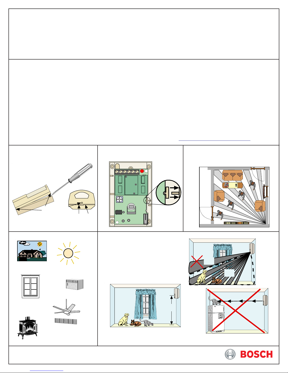
3.0 Installation
3.1 Remove the cover using a small
pet immunity, these detectors will not detect a dog up to 100 lbs (45 k) or two 60-lb (26 k) dogs, up to 10 cats, numerous rodents, or flying birds.
• Microwave Frequency:
walk testing and alarm). Only use a limited power
source up to 5 A maximum.
installations, the control unit or a Listed burglary
power supply must provide 4 hrs (64 mAh) standby
power.
rated 3 W, 125 mA, 28 VDC maximum for DC resistive
loads; protected by a 4.7 Ω, 1/2 W resistor in the
common “C” leg of the relay. Do not use with cap acitive
or inductive loads.
+120°F (-40°C to +49°C). For UL Certificated
installations, the temperature range is +32°F to +120°F
(0°C to +49°C).
flat-blade screwdriver.
3.2 Press the vertical adjust tab
toward the side of the base and lift out
the board.
DS835i/835iT: 10.525 GHz (UL Listed)
DS835iTA: 10.687 GHz (Export only, not UL Listed)
DS835iTB: 9.9 GHz (Export only, not UL Listed)
• Coverage: 35 ft by 35 f. (10.7 m by 10.7 m)
• Tamper: ("T" models only) Normally Closed (with cover on). Contacts
rated at 28 VDC, 125 mA max. Connect tamper circuit to a
24-hour protection circuit.
• Options: B335 Low Profile Swivel Mount Bracket, B338 Ceiling
Mount Bracket. (Using brackets is not recommended for pet
applications and might reduce range and increase dead zone
areas).
• Reading Bosch Security Systems, Inc. Product Date Codes
For Product Date Code information, refer to the Bosch Security Systems,
Inc. Web site at: http://www.boschsecurity.com/datecodes/
3.3 Select a mounting location.
Mount the sensor where an intruder will most
likely cross through the coverage pattern.
3.4 Avoid:
Mounting
Outdoors
Windows
and
Uninsulated
Walls
Optional anti-tamper
screws at each end
Insert screwdriver here or here
Direct S unlight
Direct Hot or
Cold
Drafts
Moving Objects
Bottom of Detector
LED ON
7.5-9ft
7.5-9ft
3.5 Observe the Pet Immunity mounting restrictions.
Note: The upper areas are not pet
immune.
7.5 - 9 ft.
(2.3 - 2.7 m)
NO
OK
Pet
Immune
Area
Heat
Sources
Air
Conditioning
Outlets
Moun t t h e detect or 7.5 - 9 feet
(2.3 - 2.7 meters) above the floor
Don't point where pets can climb.
5
5
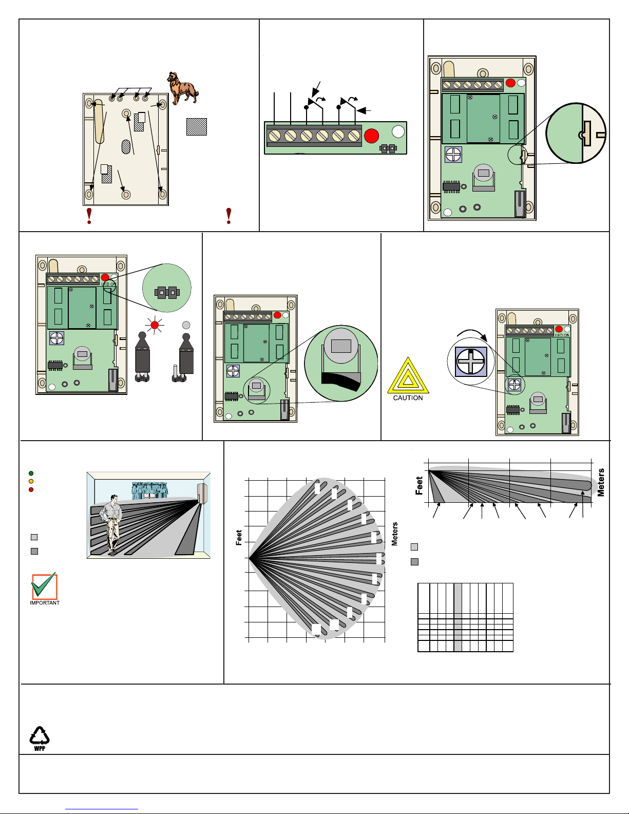
3.6 Mount the detector.
Note: Avoid possible circuit board damage by only
using the mounting hardware that is provided
in the appropriate punch-out mounting holes.
Thinwall kn o ckou t s
for wiring
Corner Mount
Surface
Mount
Don't overtighten the mounting screws
Cover may not a t ta ch correctly
B335 Bracket
applications
=
Remove
Areas
if using the
Do not use
the B335
Bracket in
pet
7.5 - 9 ft.
(2.3 - 2.7 m)
3.7 Wire the detector.
6-15
VDC
-
+
Alarm
Contacts
(DS835iT
Tamper
Contacts
LED
Normally Closed contacts
Note: Only use Limited Power
Source up to 5 A maximum.
only)
3.8 Snap the board into the base so the
notch aligns with the tab.
LED ON
7.5-9ft
7.5-9f t
7.5-9ft
3.9 Select LED operation.
3.10 In non-pet applications only, if
LED ON
7.5-9ft
7.5-9ft
ON
3.12 Walk test the detector at the time of
installation and annually thereafter.
Green = PIR detect
Yellow = MW detect
Red = Alarm
eMicrowav
Coverage
PIR
Coverage
This detector contains an
environmental stabilization
circuit. After the initial
powerup, the detector needs
approximately 2 min. to
warm up. During this time,
the detector does not
respond to any movement.
Note: Wait 2 minutes after the initial
power-up to perform Walk Tests.
5.0 FCC Notice
This device complies with Part 15 of the FCC Rules. Operation is subject to the following two conditions:
1. This device may not cause harmful interference.
2. This device must accept any interference, including interference that may cause undesired operation.
Changes or modifications not expressly approved by Bosch Security Systems. Inc. can void the user’s authority to operate the equipment.
© 2011 Bosch Security Systems, Inc.
130 Perinton Parkway, Fairport, New York 14450
www.boschsecurity.com
OFF
look-down is desired, peel away the
look-down mask. Do not remove
the clear plastic lens.
LED ON
7.5-9ft
7.5-9ft
Peel away
the mask
4.0 Coverage Patterns
0
17.5
Meters
1
2
3
0
9
10
17.5
11
10 20 30
3.11 Microwave range is pre-set. Field adjustment is
not required.
Note: If you choose to adjust the range, set the
adjustment as low as possible for proper catch
performance. Be sure to walk test throughout
the coverage pattern after any adjustment.
INCREASE
Do not use excessive
force when adjusting the
microwave pot.
Meters
10.7
0
7.5
5.3
0
0
4
5
0
6
7
Feet
Look
Down
Coverage
PIR
Coverage
6777
eMicrowav
1234567891011
8
12 22
23 33
34 44
45 55
56 66
5.3
67 77
350Feet
DS835i Lens
(inside view)
5666
10
45-5534-
44
Although generally
not required, if
masking is desired,
the lens diagram
shows the
appropriate areas to
be masked. Use an
opaque material
(such as, electrical
tape) to mask the
desired areas.
2333
DS835i/835iT Installation Instructions
P/N: F01U035203-02 Page 2
7.5-9ft
7.5-9ft
10.7
310
0
35
1-
12-
11
22
1/11
 Loading...