

Bosch DOW 1171, FK 110 LSN, SMF121 Operation Manual
Radio Frequency Fire Detection
System
DOW 1171, FK 110 LSN, SMF121
en
Operation Guide


Radio Frequency Fire Detection System Table of contents | en 3
Bosch Sicherheitssysteme GmbH Operation Guide 2016.04 | 6.0 | 4.998.120.885
Table of contents
1
Notes 4
1.1 Safety Instructions 4
1.2 Approvals and Certificates 4
2
Short Information 5
3
System Overview 6
3.1 FK 100 LSN RF Interface Module 6
3.2 DOW 1171 RF Smoke Detector 7
3.3 SMF121 RF Manual Call Point and SMF6120 Base 7
3.4 LED Functions 9
3.4.1 LEDs on FK 100 LSN Interface Module 9
3.4.2 DOW 1171 RF Smoke Detector LED 9
4
Installation/Configuration Notes 11
4.1 General Limits 11
4.2 Planning the RF Fire Detection System 11
4.3 Planning a RF Fire Detection System with DZW 1171 Radio Test Unit 13
5
Installing the RF Fire Detection System 14
5.1 Installing the FK 100 LSN RF Interface Module 14
5.2 Installing DOW 1171 RF Smoke Detector 15
5.3 Installing the SMF121 RF Manual Call Point 17
6
Wiring 18
6.1 Connection of FK 100 LSN RF Interface Module to the Fire Panel 18
6.2 Connection of SMF121 RF Manual Call Point to SMF6120 Base 19
7
Commissioning a RF Fire Detection System 20
7.1 Commissioning the FK 100 LSN RF Interface Module via WinPara / FSP-5000-RPS 21
7.2 Commissioning DOW 1171 and SMF121 RF Detectors 21
7.2.1 Logging in DOW 1171 RF Smoke Detectors to the RF Interface Module 21
7.2.2 Logging in the SMF121 RF Manual Call Points to the RF Interface Module 22
7.3 Manually Operating the FK 100 LSN RF Interface Module 23
8
Exchanging and Adding Radio Components 24
8.1 Exchanging the FK 100 LSN RF Interface Module and DOW 1171 and SMF121 RF
Detectors
24
8.2 Adding DOW 1171 and SMF121 RF Detectors using WinPara / FSP‑5000‑RPS 24
8.3 Manually Adding DOW 1171 and SMF121 RF Detectors 24
9
Maintenance and service 26
9.1 Resetting the RF Interface Module to the Delivery State 26
9.2 Replacing the Batteries in the RF Detectors 26
9.2.1 Replacing the Batteries on the DOW 1171 RF Smoke Detector 26
9.2.2 Replacing the Batteries on the SMF121 RF Manual Call Point 26
9.3 Order information 27
9.4 Repair and Disposal 27
10
Technical data 28
4 en | Notes Radio Frequency Fire Detection System
2016.04 | 6.0 | 4.998.120.885 Operation Guide Bosch Sicherheitssysteme GmbH
1 Notes
1.1 Safety Instructions
Notice!
Installation must only be carried out by authorized specialist personnel.
To guarantee the resistance to interference of the devices, only installation material approved
for installation by Bosch ST may be used.
All devices must be installed in dry areas.
!
Caution!
Electrostatic discharge (ESD)! Electronic components could become damaged. Ground
yourself using a wrist strap or take other suitable measures when handling PC boards.
Notice!
When connecting, please observe the regulations and guidelines of the regional authorities
and institutions (fire service, police, etc.)
1.2 Approvals and Certificates
An approval in line with Guideline 99/5/EC relating to short-range devices and
telecommunications transmitting devices, Annex IV, exists. This approval applies for the
following countries:
Austria (A), Belgium (B), Switzerland (CH), Germany (D), Denmark (DK), Spain (E), Great
Britain (GB), Croatia (HR), Italy (I), Luxembourg (L), Norway (N), Netherlands (NL), Portugal
(P), Sweden (S), Slovakia (SK), Slovenia (SLO).
The individual components of the RF fire detection system conform to the regulations and
guidelines for security systems EN 54, VDE 0833 and VdS.
Radio Frequency Fire Detection System Short Information | en 5
Bosch Sicherheitssysteme GmbH Operation Guide 2016.04 | 6.0 | 4.998.120.885
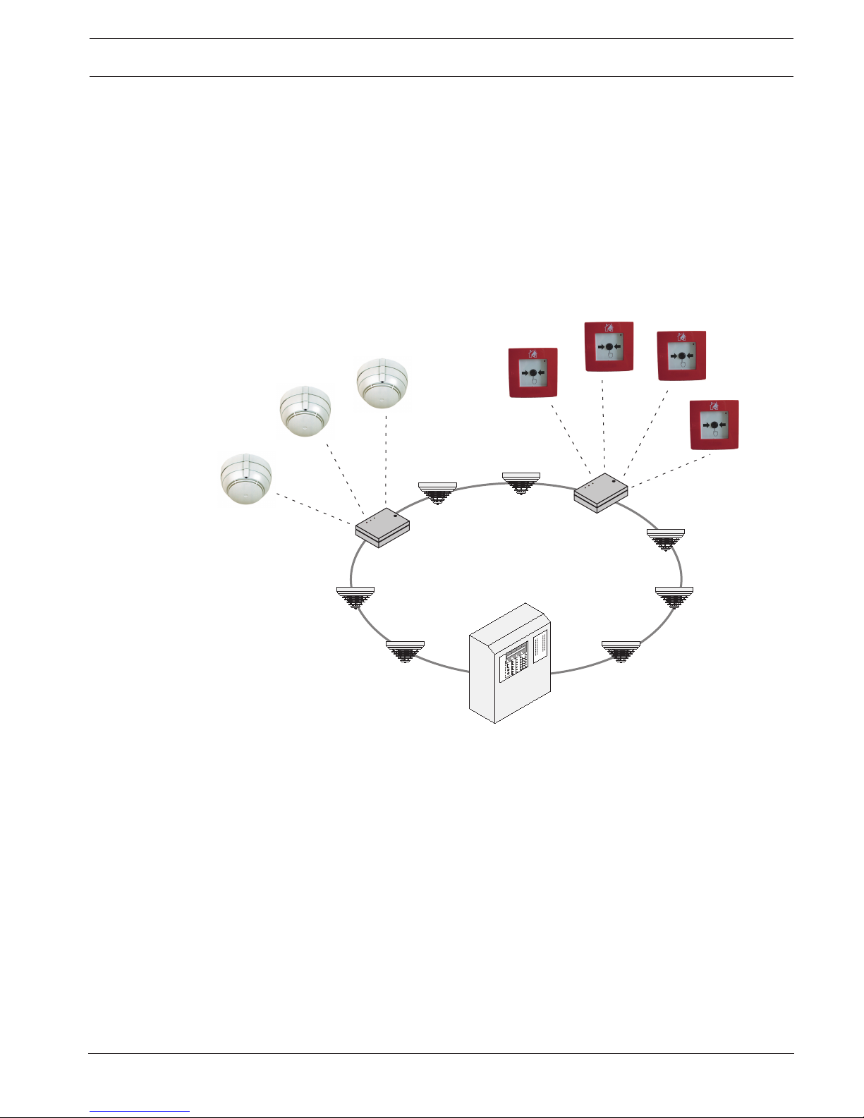
2 Short Information
The RF fire detection system consists of 1 FK 100 RF Interface Module and up to 30 RF smoke
detectors (DOW 1171 RF Smoke Detector and/or SMF121 RF Manual Call Point). As an LSN
element, FK 100 RF Interface Module is switched in a loop or stub line and forms the interface
between the RF smoke detectors and the fire panel.
Transfer of information between detector and interface module is bi-directional. If a base
channel is occupied by an external system, the system immediately switches to a secondary
channel to guarantee alarm transmission.
The RF fire detection system works in a frequency range of 868 to 870 MHz. Within this range,
a few channels are exclusively defined for radio applications in security systems. This
guarantees an extremely high level of operational stability.
1
2
3
4
5
6
7
8
9
1
0
1
1
1
2
1
3
1
4
1
5
1
6
1
7
1
8
1
9
2
0
2
1
2
2
2
3
2
4
2
5
2
6
2
7
2
8
2
9
3
0
3
1
3
2
4
9
5
0
5
1
5
2
5
3
5
4
5
5
5
6
5
7
5
8
5
9
6
0
6
1
6
2
6
3
6
4
3
3
4
3
5
3
6
3
7
3
8
3
9
4
0
4
1
4
2
4
3
4
4
4
5
4
6
4
7
4
8
FK 100 LSN
FK 100 LSN
DOW 1171
SMF121
Figure2.1: RF Fire Detection System Connection to Fire Panel
6 en | System Overview Radio Frequency Fire Detection System
2016.04 | 6.0 | 4.998.120.885 Operation Guide Bosch Sicherheitssysteme GmbH
3 System Overview
3.1 FK 100 LSN RF Interface Module
1
100
135
35,7
37,4
20
2
3
4
3
Betrieb
Störung
Alarm
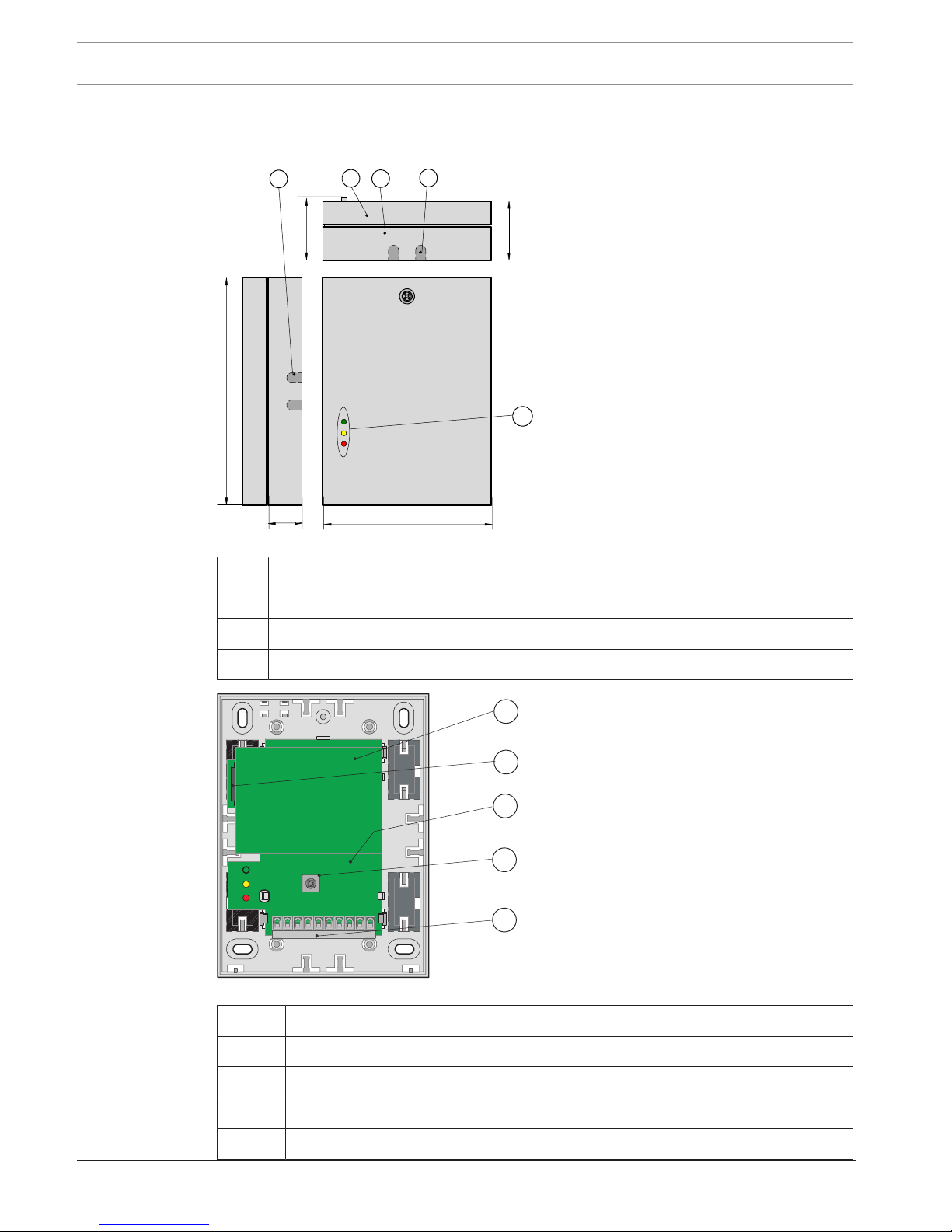
Figure3.2: FK 100 LSN configuration closed
1 Housing cover
2 Lower part of housing
3 Cable bushing
4 LED operation, fault and alarm
4
1
2
3
5
Figure3.3: FK 100 LSN configuration open
1 Radio module
2 Reed contact
3 PC board
4 Tamper contact
5 Connection terminals
Radio Frequency Fire Detection System System Overview | en 7
Bosch Sicherheitssysteme GmbH Operation Guide 2016.04 | 6.0 | 4.998.120.885
The LSN part in the interface module is powered via the LSN (LSN = Local Security Network).
The radio module is powered via an auxiliary power supply. An integrated microcontroller
drives interfaces and user elements and is responsible for data transfer between the RF fire
detector and the fire panel. The interface module has a tamper contact, a reed contact for
manual activation of the configuration mode and three LEDs for the operating status display.
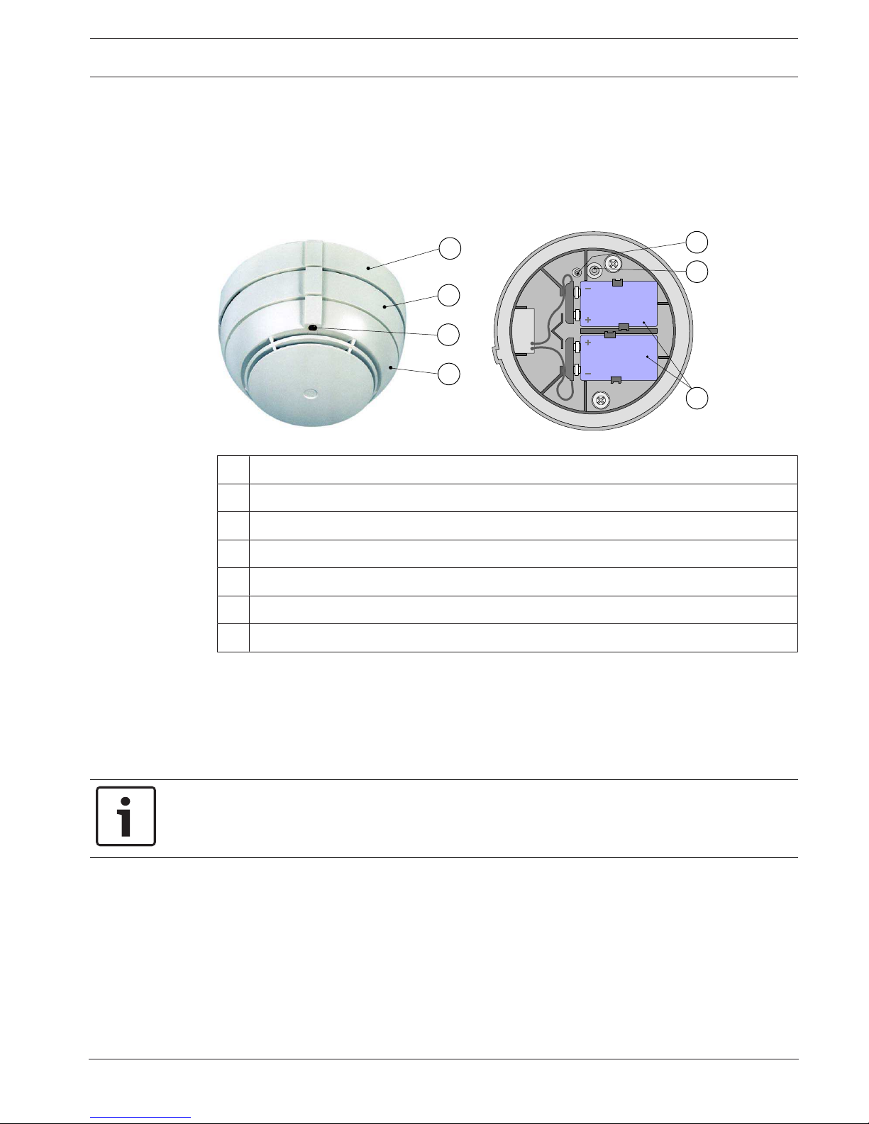
3.2 DOW 1171 RF Smoke Detector
5
6
7
4
1
2
3
Figure3.4: DOW 1171 configuration closed and open
1 Detector Bases
2 Bayonet ring
3 Red LED
4 Detector housing
5 New button for logging in and resetting
6 Contact as removal lock
7 9 V lithium battery pack
The RF smoke detector utilizes the scattered-light method, in the same way as conventional
optical smoke detectors. In conjunction with the modern detection algorithm, it achieves a
uniform response behavior, while providing high levels of interference immunity. The detector
base contains the radio module and the inserts and connections for the batteries.
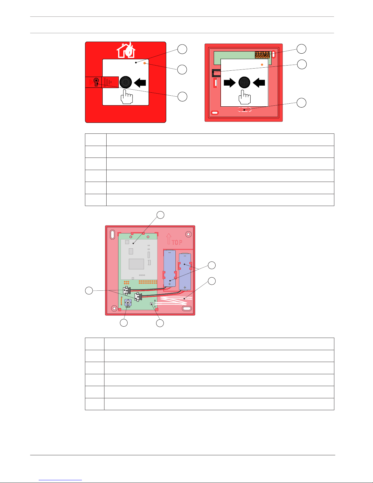
3.3 SMF121 RF Manual Call Point and SMF6120 Base
Notice!
Please note that the red LED on the RF manual call point does not light up or flash after the
alarm has been triggered. This is known and is not necessary according to EN 54-11.
8 en | System Overview Radio Frequency Fire Detection System
2016.04 | 6.0 | 4.998.120.885 Operation Guide Bosch Sicherheitssysteme GmbH
1
2
4
6
3
5
Figure3.5: SMF121 configuration closed and open
1 Glass pane
2 Red LED
3 Lock to unlock the detector door
4 Terminal block
5 Reset lever
6 Cable insertion
4
1
2
3
5
6
Figure3.6: SMF6120 Base configuration
1 Radio module
2 3.6V lithium battery
3 Cable to connect to SMF121
4 Green LED, display when logging in
5 New button for logging in
6 Battery connection
The RF manual call point consists of the SMF121 Manual Call Point and the SMF6120 Detector
Base. The detector base contains the radio module and the inserts and connections for the
batteries.
Radio Frequency Fire Detection System System Overview | en 9
Bosch Sicherheitssysteme GmbH Operation Guide 2016.04 | 6.0 | 4.998.120.885
In event of a fire, the glass pane must be broken first, and then the push button is pressed
hard. A micro switch within the detector triggers the alarm. The push button remains pressed
down. The push button or alarm can only be reset by opening the detector door or manually
operating the reset lever.
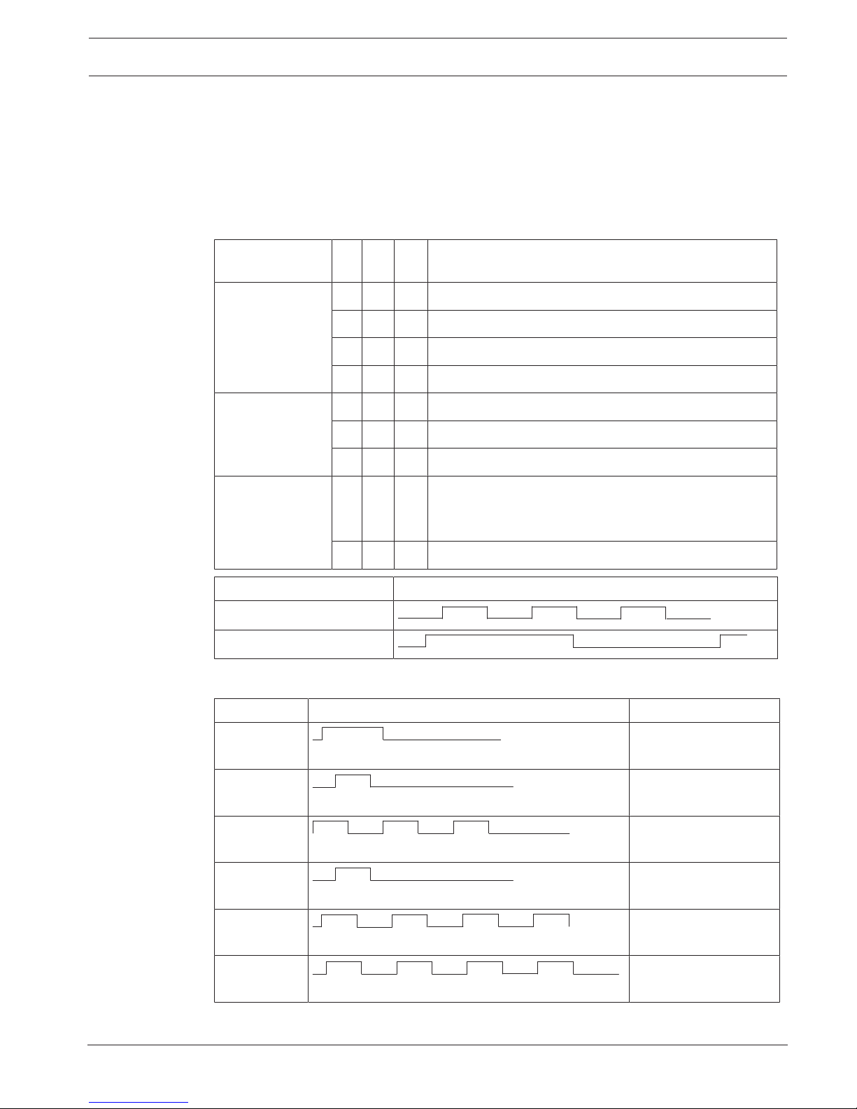
3.4 LED Functions
3.4.1 LEDs on FK 100 LSN Interface Module
Display Red YellowGreenMeaning
Rapid flashing
x x Frequency search
x RF detector login
x Commissioning without WinPara/FSP-5000-RPS
x Fault
Slow flashing
x System configuration for RF fire detection system
x Standby
x Alarm
Steady light
x Sabotage alert
(Interface module opened or detector twisted out of
base)
x Normal mode
Display Timing diagram [ms]
Rapid flashing 4Hz
125
125
125
125
125
125
125
Slow flashing 0.5Hz
1000
1000
3.4.2 DOW 1171 RF Smoke Detector LED
Flash cycle Timing diagram [ms] Meaning
Once every
2s
1680
320
System search
Once every
2s
80
1920
New logon
Three times
every 2s
80
80
80
80
1600
80
Renewed logon
Once every
1s
80
920
Alarm
Six times
every 1s
80
80
80
80
80
80
80
Fault, defect
Four times
every 1s
80
80
460
80
80
80
80
80
Field strength high

10 en | System Overview Radio Frequency Fire Detection System
2016.04 | 6.0 | 4.998.120.885 Operation Guide Bosch Sicherheitssysteme GmbH
Flash cycle Timing diagram [ms] Meaning
Three times
every 1s
80
80
80
80
600
80
Field strength
moderate
Twice every
1s
80
80
760
80
Field strength low
Once every
1s
80
920
Field strength very low
 Loading...