

Bosch DICENTIS DCNM-DE, DICENTIS DCNM-D, DICENTIS DCNM-MMD, DICENTIS DCNM-MMD2, DICENTIS DCNM-IDESK Hardware Installation Manual
...
DICENTIS
Conference System
en Hardware Installation Manual


Table of contents
1
Safety 4
2
About this manual 5
2.1 Intended audience 5
2.2 Alerts and notice signs 5
2.3 Copyright and disclaimer 5
2.4 Document history 6
3
System installation overview 7
3.1 Typical system setup 8
3.2 System extension 10
4
System installation design and planning 14
4.1 System capabilities 14
4.2 Hardware requirements 16
4.3 Power supply capacity calculation plan 17
4.3.1 Calculation using DCNM-APS(2) or DCNM-PS(2) 17
4.3.2 Calculation using PoE switches 19
4.4 Redundancy options 21
4.4.1 Redundant cabling for DCNM‑APS/DCNM‑PS units 22
4.4.2 Redundant cabling for DCNM-APS2/DCNM-PS2 units 23
4.4.3 Redundant server PC 25
5
Installation material and tools 26
5.1 System Network Cable 26
5.2 System Cable Connectors 27
5.2.1 DCNM-CBCON-I Installation Cable Connectors 28
5.2.2 DCNM-CBCON-N Network Cable Connectors 28
5.3 DCNM-CBTK System Network Cable Toolkit 29
5.4 DCNM-CB250 System Installation Cable 30
6
Mechanical installation of Central Equipment 31
6.1 Audio Powering Switch and Powering Switch 31
7
Mechanical installation of Contribution Devices 34
7.1 DICENTIS devices 34
7.2 DICENTIS Microphones 38
7.3 DCNM-MMDSP Anti-reflection foil 40
7.4 DCNM-NCH Name Card Holder 40
8
Installation Test 41
DICENTIS Table of Contents | en 3
Bosch Security Systems B.V. Hardware Installation Manual 2016.09 | V1.4 |

Safety
Prior to installing or operating products, always read the Important Safety Instructions which
are available as a separate multilingual document: Important Safety Instructions (Safety_ML).
These instructions are supplied together with all equipment that can be connected to the
mains supply.
Safety precautions
Some of the DICENTIS Conference System products are designed to be connected to the
public mains network.
To avoid any risk of electric shock, all interventions must be carried out with disconnected
mains supply.
Interventions with the equipment switched on are authorized only when it is impossible to
switch the equipment off. The operation must only be performed by qualified personnel.
Old electrical and electronic appliances
Electrical or electronic devices that are no longer serviceable must be collected separately and
sent for environmentally compatible recycling (in accordance with the European Waste
Electrical and Electronic Equipment Directive).
To dispose of old electrical or electronic devices, you should use the return and collection
systems put in place in the country concerned.
1
4 en | Safety DICENTIS
2016.09 | V1.4 | Hardware Installation Manual Bosch Security Systems B.V.
About this manual
The purpose of this manual is to provide information required for installing the DICENTIS
Conference System.
This installation manual is available as a digital document in the Adobe portable document
format (PDF).
For more information, refer to the product related information on www.boschsecurity.com
Intended audience
This hardware installation manual is intended for installers of a DICENTIS Conference System.
Alerts and notice signs
Four types of signs can be used in this manual. The type is closely related to the effect that
may be caused if it is not observed. These signs - from least severe effect to most severe
effect - are:
Notice!
Containing additional information. Usually, not observing a ‘notice’ does not result in damage
to the equipment or personal injuries.
!
Caution!
The equipment or the property can be damaged, or persons can be lightly injured if the alert
is not observed.
!
Warning!
The equipment or the property can be seriously damaged, or persons can be severely injured
if the alert is not observed.
Danger!
Not observing the alert can lead to severe injuries or death.
Copyright and disclaimer
All rights reserved. No part of this document may be reproduced or transmitted in any form by
any means, electronic, mechanical, photocopying, recording, or otherwise, without the prior
written permission of the publisher. For information on getting permission for reprints and
excerpts, contact Bosch Security Systems B.V..
The content and illustrations are subject to change without prior notice.
2
2.1
2.2
2.3
DICENTIS About this manual | en 5
Bosch Security Systems B.V. Hardware Installation Manual 2016.09 | V1.4 |

Document history
Release date Documentation version Reason
2013.08 V1.0 1st edition.
2014.07 V1.1 2nd edition.
New sections: 1 WEEE, 3.2
system ext, 5.2.1, 5.2.2.
Sections updated: 2.4, 4.3.2,
5.2, 5.3, 5.4, 7.2 +
DCNM‑MICx added.
2014.10 V1.2 3rd edition.
Sections updated: 2.4, 3.2,
4.1 and 4.3.1.
2015.07 V1.3 4th edition.
New section: 4.4, including
sub-sections: 4.4.1, 4.4.2, and
4.4.3.
Sections updated: 2.4, 3.1,
3.2, 4.1, 4.3, 4.3.1, 5.3, 5.4,
6.1, 7.4, 8.
2015.11 V1.31 5th edition.
Sections updated: 2.4, 7.1.
Terminology updated.
2016.07 V1.4 6th edition.
Terminology updated.
DCN multimedia changed to
DICENTIS.
Sections updated: 3.1, 3.2,
4.1, 4.3.1, 4.3.2, 4.4.1, 4.4.2,
4.4.3, 5.3, 5.4, 7.1, 7.2, 7.3,
7.4, 8.
2.4
6 en | About this manual DICENTIS
2016.09 | V1.4 | Hardware Installation Manual Bosch Security Systems B.V.
System installation overview
It is advisable to participate in the DICENTIS Conference System training before you install,
configure, prepare, and operate a DICENTIS Conference System.
The DICENTIS Conference System is an IP based conference system which runs on an OMNEO
compatible Ethernet network. It is used for distributing and processing audio, video and data
signals.
The DICENTIS Conference System can be quickly and easily configured as a daisy‑chain
configuration or as a star configuration:
– Daisy‑chain configuration: Uses dedicated cabling, consisting of CAT‑5e cables including
two additional power conductors (see Typical system setup, page 8).
– Star configuration: Each DICENTIS device is connected with an individual standard
CAT‑5e cable. An Ethernet switch is also required for providing Power over Ethernet
(PoE).
Notice!
When Power over Ethernet is used, DICENTIS devices cannot be daisy‑chained.
See also
– Typical system setup, page 8
3
DICENTIS System installation overview | en 7
Bosch Security Systems B.V. Hardware Installation Manual 2016.09 | V1.4 |
Typical system setup
1
8
2
4
3
9
8
8
6666
5
8
8
8
7
6
5.1
5.2
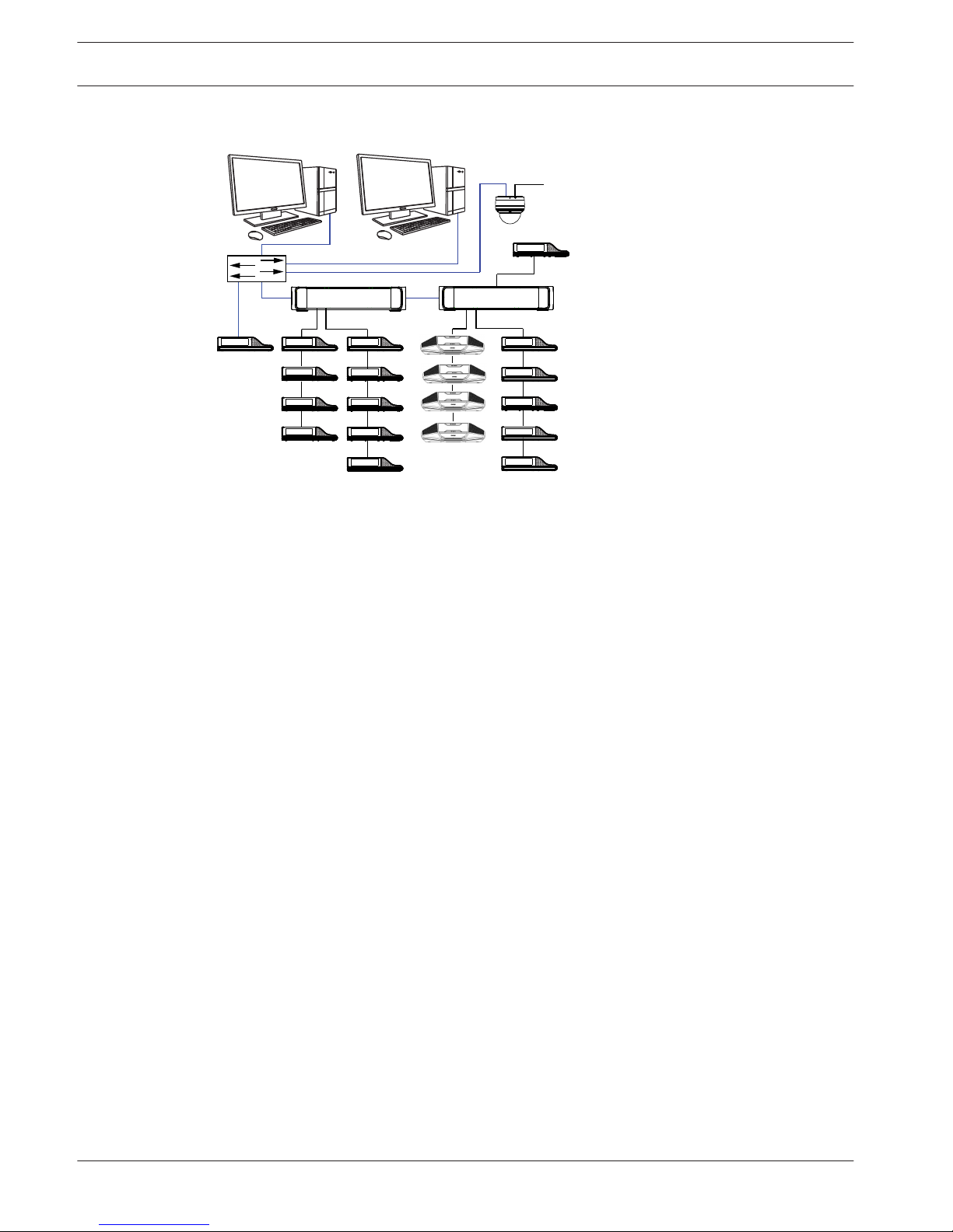
Figure 3.1: Typical DICENTIS Conference System setup
A typical DICENTIS Conference System consists of:
1. System server controller (PC):
– The heart of the system. It licenses functionality, configures and controls the system.
2. Client PC:
– Can be used to: Manage meetings, prepare meetings and configure the system.
3. Audio Powering Switch (DCNM-APS / DCNM-APS2):
– Controls the system audio, routes audio from and to the system and supplies power
to the DICENTIS devices.
4. Powering Switch (DCNM-PS / DCNM-PS2):
– Is used to increase the number of DICENTIS devices connected to the system.
5. DICENTIS devices): DCNM-D, DCNM-DVT, DCNM-DSL, DCNM-DE / DCNM-MMD, DCNMMMD2:
– Participants can use their DICENTIS device to contribute to a meeting.
– 5.1 is a DICENTIS multimedia Device used for “system power on/off”. This device is
always connected to the powered socket of the Audio Powering Switch or Powering
Switch.
Note: Only one DICENTIS multimedia Device should be connected here.
– 5.2 is a DICENTIS device used via a “Power over Ethernet” (PoE) Ethernet switch.
Note: Only one DICENTIS device should be connected here.
6. System Network Cable (DCNM‑CBxxx):
– Connects DICENTIS devices, the Audio Powering Switch, and one or more Powering
Switches to each other.
7. Ethernet switch:
– Ethernet switch with PoE on some ports.
- Routes the system data via Ethernet.
- Provides power to the DICENTIS devices via PoE.
8. CAT‑5e Ethernet cable (minimum requirement).
9. Optional HD Conference Dome (VCD‑811-IWT) + external power supply:
– Captures the image of a speaking participant.
3.1
8 en | System installation overview DICENTIS
2016.09 | V1.4 | Hardware Installation Manual Bosch Security Systems B.V.

This system overview does not give information on redundant network options. For more
information, refer to Redundancy options, page 21.
DICENTIS System installation overview | en 9
Bosch Security Systems B.V. Hardware Installation Manual 2016.09 | V1.4 |

System extension
The DICENTIS Conference System is scalable from small to medium to large. This section
describes what a small, medium and large system is and what the requirements are for these
systems:
A small DICENTIS Conference System (see Typical system setup, page 8) consists of:
– up to 100 DICENTIS devices.
– all DICENTIS devices in 1 subnet.
– 1 DICENTIS Audio Powering Switch for the audio processing.
– 1 Server PC which hosts the DICENTIS services.
A medium DICENTIS Conference System consists of:
– up to 450 DICENTIS nodes.
Refer to table X about the node count of DICENTIS equipment.
– all DICENTIS devices in 1 subnet.
– 1 DICENTIS Audio Powering Switch for the audio processing.
– 1 Server PC which hosts the DICENTIS services.
– 1 ARNI-Standard to increase the size of the system.
A large DICENTIS Conference System consists of:
– up to 750 DICENTIS devices.
– multiple subnets connected by use of a router/L3 switch.
– Each subnet can have up to 450 DICENTIS nodes.
Refer to the following table for the node count of DICENTIS equipment.
– The first subnet has:
- 1 DICENTIS Audio Powering Switch for the audio processing.
- 1 Server PC which hosts the DICENTIS services.
- 1 ARNI-Enterprise to increase the size of the system.
– All other subnets have 1 ARNI-Standard to increase the size of the system.
Note: There is no DICENTIS Audio Powering Switch in the other subnets.
Device
Node count
DICENTIS server 0
DICENTIS meeting application 0
DICENTIS Audio Powering Switch 1
DICENTIS Powering Switch 1
DICENTIS multimedia device 2
DICENTIS discussion device 1
DICENTIS discussion device select language 1
DICENTIS discussion device voting 1
DICENTIS discussion device extended 1
ARNI‑E OMNEO interface 0
ARNI‑S OMNEO interface 0
Table 3.1: Nodes count of DICENTIS equipment
3.2
10 en | System installation overview DICENTIS
2016.09 | V1.4 | Hardware Installation Manual Bosch Security Systems B.V.

An ARNI (Audio Routed Network Interface) is used to increase the number of DICENTIS
devices on a single subnet and to connect multiple DICENTIS system subnets. If more than
one subnet is required, two types of an ARNI must be used.
– OMN-ARNIS (ARNI‑S OMNEO interface): The ARNI‑S is required for increasing the system
size above 100 DICENTIS devices. It supports up to 450 DICENTIS nodes in its subnet. It
also acts as a DHCP server in its subnet.
– OMN-ARNI‑E (ARNI‑E OMNEO interface): The ARNI‑E is required for increasing the system
size above 450 DICENTIS nodes. It supports up to 450 DICENTIS nodes in its subnet. It
also acts as a DHCP server in its subnet. It can connect up to 40 subnets, each with an
ARNI‑S.
Defining subnets and subnet masks
A subnet is a logical, visible subdivision of an IP network. The number of DICENTIS devices
that can be in the same subnet depends on the subnet mask.
A standard class C subnet (255.255.255 or /24) can contain 254 IP addresses. Some
DICENTIS devices have 2 IP addresses. For this reason, Bosch advises to use 255.255.252.0
(or /22) as a subnet mask. This allows you to have 1018 IP addresses. The following table lists
the number of IP address per DICENTIS device in a DICENTIS Conference System.
Device
IP addresses
DICENTIS server (optional Meeting Application) 1
Client PC running DICENTIS meeting application 1
DICENTIS Audio Powering Switch 1
DICENTIS Powering Switch 1
DICENTIS multimedia device 2
DICENTIS discussion device 1
DICENTIS discussion device select language 1
DICENTIS discussion device voting 1
DICENTIS discussion device extended 2
ARNI‑Enterprise 1
ARNI‑Standard 1
IP camera 1
SDI video switcher 1
Table 3.2: Nodes count of DICENTIS equipment
Maximum number of DICENTIS devices in a string:
– The max age timer should be set to 22 when RSTP is used for cable redundancy to
prevent a defective cable or powering switch from influencing the system.
– Each time data hops from one switch to another, the age is increased by one. This timer
can be reached or exceeded, because a daisy chain can be used to loop through the
DICENTIS devices.
DICENTIS
System installation overview | en 11
Bosch Security Systems B.V. Hardware Installation Manual 2016.09 | V1.4 |

– This timer (or restriction) cannot be reached when there is no cable redundancy. This is
because the power limitation will be reached before the max age restriction is reached.
– The timer can be reached when:
– you use cable redundancy.
– the system is incorrectly wired.
12 en | System installation overview DICENTIS
2016.09 | V1.4 | Hardware Installation Manual Bosch Security Systems B.V.
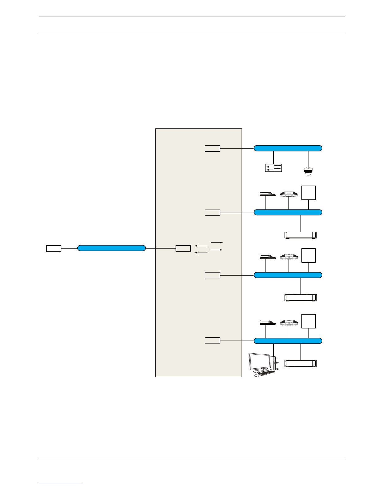
Multi subnet DICENTIS Conference System
The following figure illustrates a typical multi subnet DICENTIS Conference System with a total
of 1200 DICENTIS devices.
– The system is divided over four (4) subnets, where two (2) subnets having a maximum of
400 DICENTIS devices and an OMN-ARNIS are connected.
– The system has one OMN-ARNIS installed in the first subnet with a maximum of 400
DICENTIS devices connected (Note that only one OMN-ARNIS is allowed within a multiple
subnet DICENTIS Conference System).
– Subnet four (4): When using multiple subnets, make sure that all cameras needed to
capture video of the seats are all connected to the same subnet.
192.168.64.x
OMN-ARNI-E
192.168.64.1
VLAN64
192.168.65.254
Ports 1, 2, 3, 4
L3 Switch
VLAN66
192.168.67.254
Ports 5, 6, 7, 8
VLAN74 (internet)
192.168.1.253
Ports 17, 18, 19, 20
VLAN68
192.168.69.254
Ports 9, 10, 11, 12
VLAN70
192.168.71.255
Internal DHPC server
Ports 13, 14, 15, 16
Internet Router
192.168.1.254
DCNM-APS
DCNM server PC
DCNM-PS
DICENTIS devices
Max. 420 nodes
DICENTIS devices
Max. 420 nodes
DICENTIS devices
Max. 420 nodes
DCNM-PS
OMN-ARNI-S
192.168.66.1
OMN-ARNI-S
192.168.68.1
192.168.66.x
192.168.1.x
192.168.68.x
192.168.70.x
1
2
Figure 3.2: Typical DICENTIS Conference System with multiple subnets
– 1: External video switcher.
– 2: Dome camera.
See also
– System extension, page 10
DICENTIS System installation overview | en 13
Bosch Security Systems B.V. Hardware Installation Manual 2016.09 | V1.4 |
System installation design and planning
Before you start to install system devices and connect system cabling, you should make a
system design and planning:
– Familiarize yourself with the product and system capabilities.
– Make a cable (connection) plan:
– Calculate the system network cable length.
– Calculate the system power consumption.
– Calculate the required power capacity of the system.
Notice!
The DICENTIS Conference System uses the RSTP protocol when redundant cabling mode is
enabled. If the DICENTIS Conference System needs to be connected with the locally present
network, please consult the local IT department before continuing with the installation
design.
Notice!
Make sure that the cable lengths and power consumptions do not exceed the specifications.
Not doing so will result in malfunctioning at any moment of the DICENTIS Conference System
and products.
System capabilities
The capability of the DICENTIS Conference System and DICENTIS products depends on:
– The lengths of the system network cables.
– The number of connected devices.
– The system power supply capacity.
Cable length
System network cables (DCNM‑CBxx) lengths (2, 5, 10 or 25 m) have a direct effect on the
available power supply capacity. The longer the system network cable, the less power supply
capacity is available to drive the connected devices. Therefore, choose the lengths of the
system network cables carefully.
Notice!
Custom network cables must never exceed the maximum Ethernet specification of 100m
(IEEE 802.3ab).
Keep your network hierarchy as flat as possible. This means having as few levels as possible.
It is recommended not to exceed 7 levels. See the following example: 1: 1st level = Root
switch, 2: 2
nd
level = switch, 3: 3
rd
level = switch.
4
4.1
14 en | System installation design and planning DICENTIS
2016.09 | V1.4 | Hardware Installation Manual Bosch Security Systems B.V.
 Loading...