

Bosch DICENTIS Hardware Installation Manual
DICENTIS
Conference System
en
Hardware Installation Manual


DICENTIS Table of contents | en 3
Bosch Security Systems B.V. Hardware Installation Manual 2018.09 | V1.8 |
Table of contents
1
Safety 4
2
About this manual 6
2.1 Intended audience 6
2.2 Alerts and notice signs 6
2.3 Copyright and disclaimer 6
2.4 Document history 6
3
System installation overview 9
3.1 Typical system setup 10
3.2 System extension 13
4
System installation design and planning 17
4.1 System capabilities 17
4.2 Hardware requirements 19
4.3 Power supply capacity calculation plan 22
4.3.1 Calculation using DCNM-APS(2) or DCNM-PS(2) 22
4.3.2 Calculation using PoE switches 24
4.4 Redundancy options 26
4.4.1 Redundant cabling for DCNM‑APS/DCNM‑PS units 27
4.4.2 Redundant cabling for DCNM-APS2/DCNM-PS2 units 28
4.4.3 Redundant server PC 30
5
Installation material and tools 31
5.1 DICENTIS System Cable Assemblies 31
5.2 DCNM-CBCON Connectors for DICENTIS cable 32
5.3 DCNM-CBTK System Network Cable Toolkit 33
5.4 DCNM-CB250-I System Installation Cable 34
5.5 DCNM-CBCPLR Cable couplers 35
5.5.1 Using a cable coupler to extend a cable 35
5.5.2 Using a cable coupler as a break-out box 35
5.5.3 Using a cable coupler as an interface between different types of cable 36
5.5.4 Using a cable coupler to insert power locally 38
6
Mechanical installation of Central Equipment 40
6.1 Audio processor and powering switch and Powering switch 40
7
Mechanical installation of Contribution Devices 43
7.1 DICENTIS devices 43
7.2 DCNMM-IDESK / DCNM-IDESKVID Interpreter desk 46
7.3 DICENTIS Microphones 49
7.4 DCNM-MMDSP Anti-reflection foil 51
7.5 DCNM-NCH Name Card Holder 51
7.6 DCNM-IDESKINT On-air & telephone interface DCNM-IDESK 52
8
Installation Test 53
4 en | Safety DICENTIS
2018.09 | V1.8 | Hardware Installation Manual Bosch Security Systems B.V.
1 Safety
Prior to installing or operating products, always read the Important Safety Instructions which
are available as a separate multilingual document: Important Safety Instructions (Safety_ML).
These instructions are supplied together with all equipment that can be connected to the
mains supply.
Safety precautions
Some of the DICENTIS Conference System products are designed to be connected to the
public mains network.
To avoid any risk of electric shock, all interventions must be carried out with disconnected
mains supply.
Interventions with the equipment switched on are authorized only when it is impossible to
switch the equipment off. The operation must only be performed by qualified personnel.
Old electrical and electronic appliances
Electrical or electronic devices that are no longer serviceable must be collected separately and
sent for environmentally compatible recycling (in accordance with the European Waste
Electrical and Electronic Equipment Directive).
To dispose of old electrical or electronic devices, you should use the return and collection
systems put in place in the country concerned.
Class A equipment (commercial broadcasting equipment)
This equipment is for professional (Class A) electromagnetic compatibility equipment. Seller
or user should pay attention to this point. It is intended for use outside the home.
!
Warning!
Changes or modifications not expressly approved by Bosch Security Systems could void the
user’s authority to operate the equipment.
FCC Statements - Class A digital device
This equipment has been tested and found to comply with the limits for a Class A digital
device, pursuant to part 15 of the FCC Rules. These limits are designed to provide reasonable
protection against harmful interference when the equipment is operated in a commercial
environment. This equipment generates, uses, and can radiate radio frequency energy and, if
not installed and used in accordance with the instruction manual, may cause harmful
interference to radio communications. Operation of this equipment in a residential area is
likely to cause harmful interference in which case the user will be required to correct the
interference at his/her own expense.
IC Statement
This device complies with Industry Canada license-exempt RSS standard(s). Operation is
subject to the following two conditions:
(1) this device may not cause interference, and
(2) this device must accept any interference, including interference that may cause undesired
operation of the device.
Le présent appareil est conforme aux CNR d'Industrie Canada applicables aux appareils radio
exempts de licence. L'exploitation est autorisée aux deux conditions suivantes :
(1) l'appareil ne doit pas produire de brouillage, et

DICENTIS Safety | en 5
Bosch Security Systems B.V. Hardware Installation Manual 2018.09 | V1.8 |
(2) l'utilisateur de l'appareil doit accepter tout brouillage radioélectrique subi, même si le
brouillage est susceptible d'en compromettre le fonctionnement.
6 en | About this manual DICENTIS
2018.09 | V1.8 | Hardware Installation Manual Bosch Security Systems B.V.
2 About this manual
The purpose of this manual is to provide information required for installing the DICENTIS
Conference System.
This installation manual is available as a digital document in the Adobe portable document
format (PDF).
For more information, refer to the product related information on www.boschsecurity.com
2.1 Intended audience
This hardware installation manual is intended for installers of a DICENTIS Conference System.
2.2 Alerts and notice signs
Four types of signs can be used in this manual. The type is closely related to the effect that
may be caused if it is not observed. These signs - from least severe effect to most severe
effect - are:
Notice!
Containing additional information. Usually, not observing a ‘notice’ does not result in damage
to the equipment or personal injuries.
!
Caution!
The equipment or the property can be damaged, or persons can be lightly injured if the alert
is not observed.
!
Warning!
The equipment or the property can be seriously damaged, or persons can be severely injured
if the alert is not observed.
Danger!
Not observing the alert can lead to severe injuries or death.
2.3 Copyright and disclaimer
All rights reserved. No part of this document may be reproduced or transmitted in any form by
any means, electronic, mechanical, photocopying, recording, or otherwise, without the prior
written permission of the publisher. For information on getting permission for reprints and
excerpts, contact Bosch Security Systems B.V..
The content and illustrations are subject to change without prior notice.
2.4 Document history
Release date Documentation version Reason
2013.08 V1.0 1st edition.
2014.07 V1.1 2nd edition.
New sections: 1 WEEE, 3.2
system ext, 5.2.1, 5.2.2.

DICENTIS About this manual | en 7
Bosch Security Systems B.V. Hardware Installation Manual 2018.09 | V1.8 |
Release date Documentation version Reason
Sections updated: 2.4, 4.3.2,
5.2, 5.3, 5.4, 7.2 +
DCNM‑MICx added.
2014.10 V1.2 3rd edition.
Sections updated: 2.4, 3.2,
4.1 and 4.3.1.
2015.07 V1.3 4th edition.
New section: 4.4, including
sub-sections: 4.4.1, 4.4.2, and
4.4.3.
Sections updated: 2.4, 3.1,
3.2, 4.1, 4.3, 4.3.1, 5.3, 5.4,
6.1, 7.4, 8.
2015.11 V1.31 5th edition.
Sections updated: 2.4, 7.1.
Terminology updated.
2016.07 V1.4 6th edition.
Terminology updated.
DCN multimedia changed to
DICENTIS .
Sections updated: 3.1, 3.2,
4.1, 4.3.1, 4.3.2, 4.4.1, 4.4.2,
4.4.3, 5.3, 5.4, 7.1, 7.2, 7.3,
7.4, 8.
2017.10 V1.5 7th edition.
Terminology and product
names updated.
New section: 5.5
Sections updated: 5.2.1,
5.2.2, 7.1 new radio
interference warning added.
2017.12 V1.6 8th edition.
Sections updated: 5.5.3,
5.5.4.
2018.04 V1.7 9th edition.
Sections updated: 3.1, 3.2,
4.3.1, 4.3.2, 4.4, 5.2, 5.4,
5.5.4.
New section: 7.2 DCNMIDESK and DCNM-IDESKVID
Interpreter desk added.
2018.09 V1.8 10th edition.
Sections updated: 1, 7.2.

8 en | About this manual DICENTIS
2018.09 | V1.8 | Hardware Installation Manual Bosch Security Systems B.V.
Release date Documentation version Reason
New section: 7.2 DCNMIDESKINT On-air & telephone
interface DCNM-IDESK
DICENTIS System installation overview | en 9
Bosch Security Systems B.V. Hardware Installation Manual 2018.09 | V1.8 |
3 System installation overview
It is advisable to participate in the DICENTIS Conference System training before you install,
configure, prepare, and operate a DICENTIS Conference System.
The DICENTIS Conference System is an IP based conference system which runs on an OMNEO
compatible Ethernet network. It is used for distributing and processing audio, video and data
signals.
The DICENTIS Conference System can be quickly and easily configured as a daisy‑chain
configuration or as a star configuration:
– Daisy‑chain configuration: Uses dedicated cabling, consisting of CAT‑5e cables including
two additional power conductors (see Typical system setup, page 10).
– Star configuration: Each DICENTIS device is connected with an individual standard
CAT‑5e cable. An Ethernet switch is also required for providing Power over Ethernet
(PoE).
Notice!
When Power over Ethernet is used, DICENTIS devices cannot be daisy‑chained. Please use
unshielded cable for the DICENTIS discussion devices.
See also
– Typical system setup, page 10
10 en | System installation overview DICENTIS
2018.09 | V1.8 | Hardware Installation Manual Bosch Security Systems B.V.
3.1 Typical system setup
1
8
2
4
3
9
8
8
6666
5
8
8
8
7
6
5.1
5.2
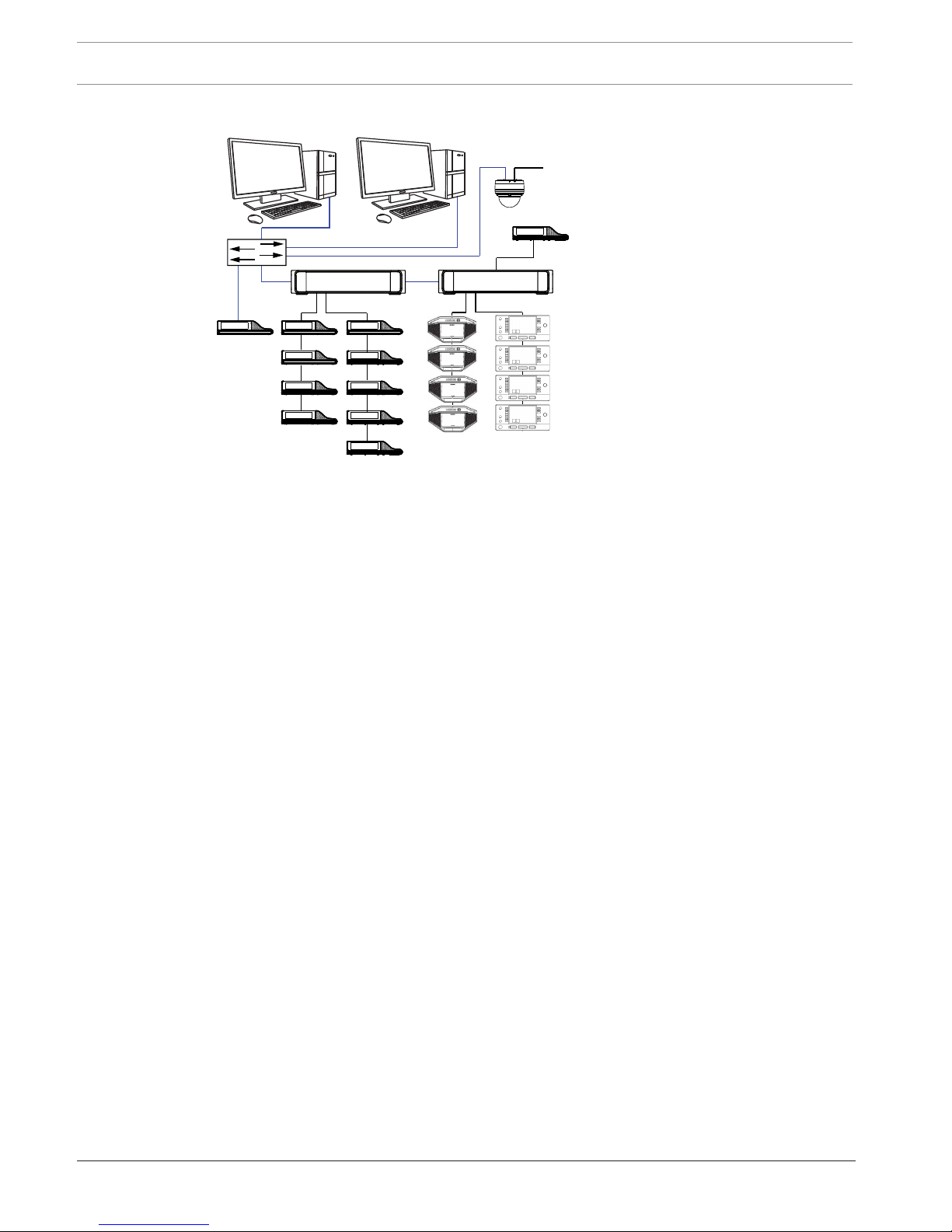
Figure3.1: Typical DICENTIS Conference System setup
A typical DICENTIS Conference System consists of:
1. System server controller (PC):
– The heart of the system. It licenses functionality, configures and controls the system.
2. Client PC:
– Can be used to: Manage meetings, prepare meetings and configure the system.
3. Audio processor and powering switch (DCNM-APS / DCNM-APS2):
– Controls the system audio, routes audio from and to the system and supplies power
to the DICENTIS devices.
4. Powering switch (DCNM-PS / DCNM-PS2):
– Is used to increase the number of DICENTIS devices connected to the system.
5. DICENTIS devices: DCNM-D, DCNM-DVT, DCNM-DSL, DCNM-DE / DCNM-MMD2, DCNMMMD:
– Participants can use their DICENTIS device to contribute to a meeting.
– 5.1 is a DICENTIS Multimedia device used for “system power on/off”. This device is
always connected to the powered socket of the Audio processor and powering
switch or Powering switch.
Note: Only one DICENTIS Multimedia device should be connected here.
– 5.2 is a DICENTIS device used via a “Power over Ethernet” (PoE) Ethernet switch.
Note: Only one DICENTIS device should be connected here.
– 5.3 are DICENTIS Interpretation desks: DCNM-IDESK and DCNM-IDESKVID. Provides
extensive facilities for professional interpretation for the DICENTIS Conference
System.
Note: A maximum of 10 desks can be installed per booth.
6. System Network Cable (DCNM‑CBxxx):
– Connects DICENTIS devices, the Audio processor and powering switch, and one or
more Powering switches to each other.
7. Ethernet switch:
– Ethernet switch with PoE on some ports.
- Routes the system data via Ethernet.
- Provides power to the DICENTIS devices via PoE.
DICENTIS System installation overview | en 11
Bosch Security Systems B.V. Hardware Installation Manual 2018.09 | V1.8 |
8. CAT‑5e Ethernet cable (minimum requirement).
9. Optional video camera (Onvif Profile-S compatible cameras, Sony IP cameras via CGI
commands, or Panasonic HD Integrated IP) + external power supply:
– Captures the image of a speaking participant.
Note: The Sony camera needs to be placed in a separate VLAN to avoid problems with the
multicast data.
Note: The Panasonic camera requires an external H.264 encoder if the SDI video needs to
be displayed on the multimedia devices (or in the Meeting Application).
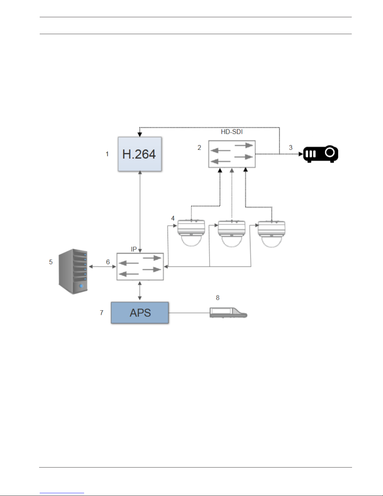
Figure3.2: Typical camera setup
A typical camera setup in a DICENTIS Conference System consists of:
1. H.264 encoder to encode the HD SDI video to H.264
2. HD-SDI switcher
3. Projector
4. Video camera (Onvif Profile-S compatible camera, Sony, Panasonic)
5. System server controller (PC)
6. L3 Ethernet switch
7. Audio processor and powering switch (DCNM-APS / DCNM-APS2)
8. DCNM-MMD2
Cables:
– Dotted line = HD-SDI (coax cable)
– Black with arrow = Ethernet TCP/IP
– Black straight line = DCNM-cable
 Loading...