

Page 1
Operating Instructions D5070 Analog Device Programmer
Notices
Use these instructions when operating the D5070
Analog Device Programmer in an analog circuit
controlled by the D8024, D9024, or D10024 Analog
Fire Alarm Control Panels (FACPs).
Operate, test, and maintain the
D5070 according to these
instructions, NFPA 72, local codes,
and the authority having jurisdiction
(AHJ).
Follow the procedures in these
instructions to avoid personal injury
and damage to the equipment. Failure
to follow these instructions can result
in the D5070 not operating properly.
Bosch is not responsible for
improperly installed, tested, or
maintained D5070 Programmers.
NFPA 72 requires a complete systemwide functional test be performed
after modifying, repairing, upgrading,
or adjusting system components,
hardware, wiring, programming,
software, and firmware.
1.0 Description
The D5070 (Figure 1) is a hand-held device used to
program address settings on electrically erasable
programmable read-only memory (EEPROM)
programmable analog devices. Use the D5070 base
to program the detector head, use the
module-programming adapter to program the relay
module and point contact module. With the exception
of the D339A Point Contact Module, all relay modules
and point contact modules are programmed this way.
The D5070 requires terminal block wiring to set the
addresses. Refer to Section 2.2 Accessory Module Address
Setting on page 2 for address setting instructions.
The detector head twist mounts on the base contacts.
The module-programming adapter’s non-polarized
plug attaches to the address programming pins on the
relay modules and point contact modules. The
programming jack end of the adapter plugs into the
D5070.
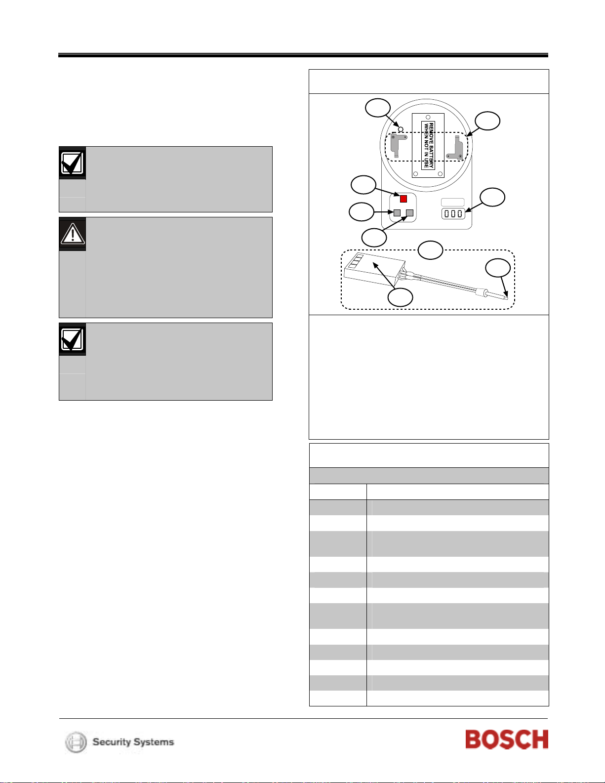
Figure 1: D5070 Analog Device Programmer
1
2
3
6
4
5
7
9
8
1 - Module programming jack receptacle
2 - Twist on the detector head here.
3 - Red programming button
4 - Power On programming button
5 - Power Off programming button
6 - Display
7 - Module programming adapter
8 - Non-polarized plug
9 - To remote programming jack
Table 1: D5070 Compatible Devices
Model Description
D322A Analog heat detector
D323A Analog photoelectric smoke detector
D323A-DH Replacement photoelectric smoke detector
head for analog duct detectors
D324A Analog ionization smoke detector
D325A Analog manual fire alarm station
D326A Analog point contact module
D327A Analog notification appliance circuit (NAC)
output module
D328A Analog relay module
D331A Analog duct detector
D332A Analog duct detector with Form C relays
D333A Analog circuit fault isolator
D339A Analog point contact module
Page 2
D5070
2.0 Setting an Address
Ensure the battery inside the D5070 is
connected before setting an address.
2.1 Detector Head Address Setting
To set the detector head address for the D322A,
D323A, and D324A:
1. Place the detector head on the programmer,
aligning the head tabs with the tab grooves
(Figure 2).
2. Turn the detector head clockwise, attaching the
detector head.
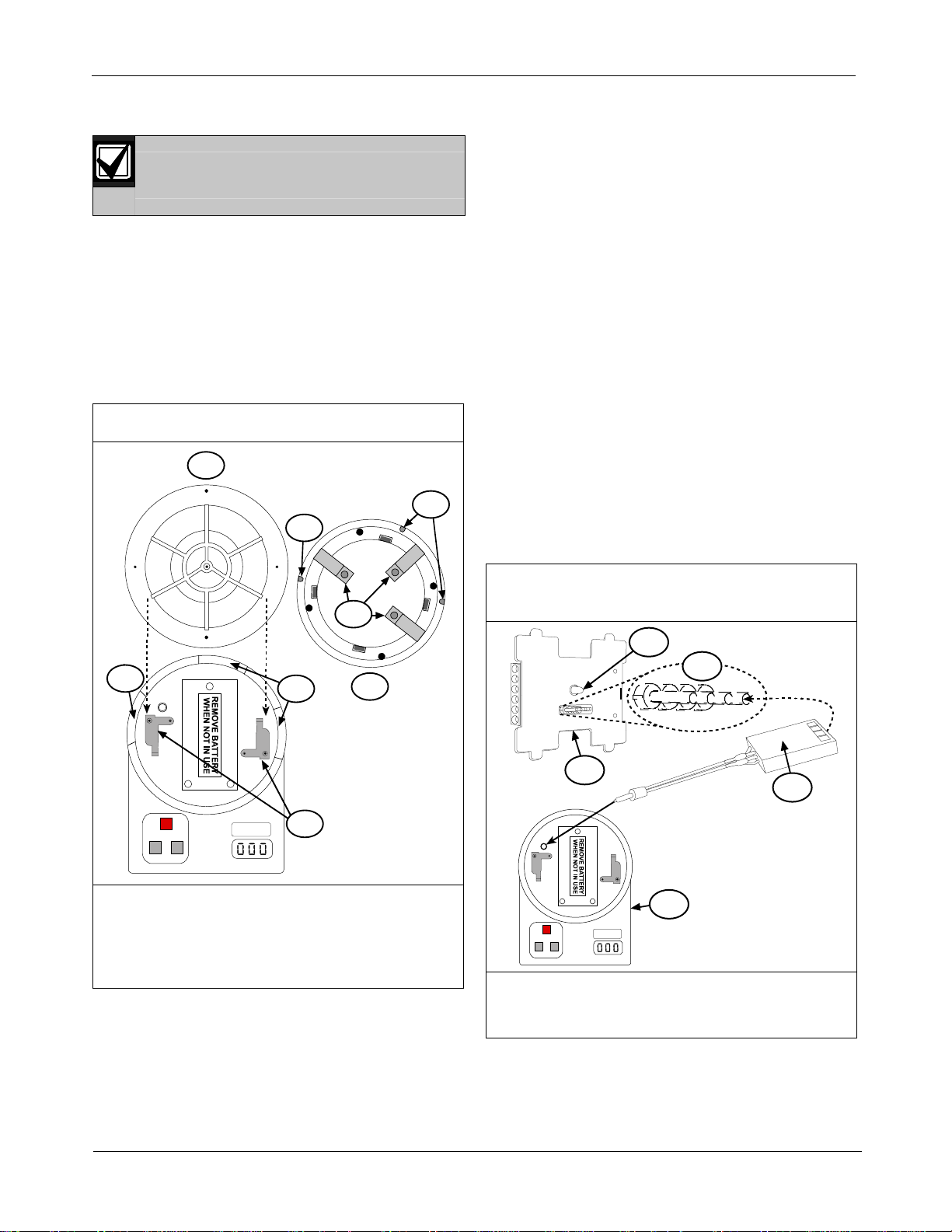
Figure 2: D5070 Detector Head
1
6
6
4. Set the required address by pressing the Power On
and Power Off buttons until the desired address
appears.
The Power On button automatically reads the
detector or module address and advances the
address by ten. The Power Off button advances the
detector or device address by one.
When the address being programmed is different
from the device’s current address, the display
shows three red flashing dots.
5. When the desired address appears, press the red
programming button to store that address.
The three red dots on the display disappear.
2.2 Accessory Module Address Setting
To set the address for the D326A, D327A, D328A,
D334A, and D339A:
1. Insert the non-polarized plug on the programming
adapter into the module EEPROM microchip port.
2. Plug the remote programming adapter’s
programming jack into the remote programming
jack receptacle on the D5070 Analog Device
Programmer. Refer to Figure 3.
5
2
1 - Detector head
(top view)
2 - Tab grooves (3)
3 - Programmer
contacts (2)
2
3
4 - Detector head
5 - Head contacts (3)
6 - Head tabs (3)
4
(bottom view)
3. Press the Power On button to activate the D5070.
A battery check message appears followed by the
device address.
Figure 3: Accessory Module and D5070
Connection
1
2
3
5
1 - Status LED
2 - Address
programming pins
3 - D326A, D334A
4 - Non-polarized plug
5 - D5070 Module
3. Press the Power On button to activate the D5070.
A battery check message appears followed by the
device address.
4
2 Bosch | 2/06 | 39024E
Page 3

4.
Set the required address by pressing the Power On
and Power Off buttons until the desired address
appears.
The Power On button automatically reads the
detector or module address and advances the
address by ten. The Power Off button advances the
detector or device address by one.
When the address being programmed is different
from the device’s current address, three red
flashing dots appear on the display.
5.
When the desired address appears, press the red
programming button to store that address.
The three red dots on the display disappear.
2.3 D339A Analog Point Contact Module
Address Setting
1. Program the D339A address by attaching the black
and red wires extending from the
module-programming adapter to the D339A
terminal block (Figure 4).
D5070
3.0 Reading Analog Value
The D324A Detector Heads require a
30 sec stabilization period. Do not read the
To read a detector head or an accessory module analog
value:
1.
Connect the detector head or accessory module to
Press the red programming button.
2.
ionization detector analog value during this
period.
the D5070 as described in Section 2.1 Detector Head
Address Setting or Section 2.2 Accessory Module Address
Setting on page 2.
An A appears followed by the analog value. This
value is continuously updated for 3 min or until the
D5070 is turned off.
Figure 4: D339A Programming Connections
1
4 5
B
2
A
SC (OUT)
S (OUT)
SC (IN)
S (IN)
3
1 - To module programming jack receptacle
2 - Black wire
3 - Red wire
4 - Terminal block
5 - D339A Module
2. Plug the module programming adapter jack into
the D5070 module programming adapter
receptacle. Then follow Step 2 through Step 5 in
Section 2.2 Accessory Module Address Setting on page 3.
Bosch | 2/06 | 39024E 3
Page 4

4.0 Display Messages
Table 2: Display Messages
Message Description
bat
E0
E1
E2
E3
E4
E5
E6
Table 3: Analog Device Information Table
Device Standard
D322A Heat
Detector
D323A Photoelectric
Detector
D323A-DH Analog
Duct Detector
Replacement Head
D324A Ionization
Detector
D325A Manual Pull
Station
D326A Point Contact
Module
D327A NAC Output
Module
D334A Point Contact
Module
* Percent (%) values can only be read from the FACP.
Battery check. Appears at power up and when the battery is low. A low battery is useful for up to 3000 address
setting operations.
The control panel does not recognize addresses above 127.
Attempting to program an address with no device connected.
Cannot find the device after power up or replace the device.
Replace detector.
Cannot locate the device to program.
Device read error.
Failure during analog value reading.
Pre-Alarm
Threshold*
+113°F
(+45°C)
2.5% 3% 0.1% 0.5% to 4%
2.5% 3% 0.1% 0.5% to 4%
1% 1% 1%
16 64
16 44 64
16 44
16 44 64
Standard Fire
Threshold*
+142°F
(+61°C)
Just
Calibrated
*
Range
*
+136°F to +149°F
(+58°C to +65°C)
Normal
Reading
Fault
Input
Fire
© 2006 Bosch Security Systems, Inc.
130 Perinton Parkway, Fairport, NY 14450-9199 USA
Customer Service: (800) 289-0096; Technical Support: (888) 886-6189
39024E
Operating Instructions
2/06
D5070
Page 4 of 4
 Loading...