

Bosch D6412, D4412 Operation And Installation Manual
Operation and Installation Guide
Control Panels D6412/D4412

D6412/D4412
Contents
Contents
1.0 Introduction ............................................................................................................................................................................................. 7
1.1 Organization ........................................................................................................................................................................... 7
1.2 Other Literature Referenced ............................................................................................................................................. 8
1.3 Documentation Conventions ............................................................................................................................................. 8
1.3.1 Type Styles Used in this Guide ......................................................................................................................................... 8
1.3.2 Tips, Important Notes, Cautions, and Warnings ........................................................................................................... 8
1.4 FCC Notice ............................................................................................................................................................................ 9
1.4.1 Part 15 ..................................................................................................................................................................................... 9
1.4.2 Part 68 ..................................................................................................................................................................................... 9
2.0 Overview................................................................................................................................................................................................. 10
2.1 Specifications ......................................................................................................................................................................10
2.2 SIA Control Panel Standard ............................................................................................................................................12
2.3 Standard Features .............................................................................................................................................................. 12
2.3.1 Points ..................................................................................................................................................................................... 12
2.3.2 Areas and Accounts ........................................................................................................................................................... 12
2.3.3 Communicator ..................................................................................................................................................................... 12
2.3.4 Command Centers ............................................................................................................................................................. 13
2.3.5 Keyswitch .............................................................................................................................................................................. 13
2.3.6 Alarm Event Memory .......................................................................................................................................................... 13
2.3.7 Event Log .............................................................................................................................................................................. 13
2.3.8 EMI/Lightning Transient Protection ............................................................................................................................... 13
2.3.9 Programming ........................................................................................................................................................................ 13
2.3.10 Other Features .................................................................................................................................................................... 13
2.3.11 Control Panel Assembly .................................................................................................................................................... 14
2.3.12 Listings and Approvals ....................................................................................................................................................... 14
3.0 Installation ............................................................................................................................................................................................. 15
3.1 Before You Begin ................................................................................................................................................................ 15
3.2 Enclosure Options .............................................................................................................................................................. 15
3.3 Premises Wiring ..................................................................................................................................................................15
3.4 Installing the Assembly ...................................................................................................................................................... 16
3.4.1 Connecting Earth Ground ................................................................................................................................................ 16
3.4.2 Closing the Installer Switch ............................................................................................................................................. 16
3.5 Finishing the Installation ................................................................................................................................................... 17
3.5.1 Earth Ground and Installer Switch ................................................................................................................................. 17
3.5.2 Charge the Battery as You Finish ................................................................................................................................... 17
3.5.3 Install and Wire Detection Devices ............................................................................................................................... 17
3.5.4 Install Modules ..................................................................................................................................................................... 17
3.5.5 Make the Telephone Connections .................................................................................................................................. 17
3.5.6 Connect the On-Board Points and Command Centers ........................................................................................... 17
3.5.7 Power Up ............................................................................................................................................................................... 18
3.6 Programming the Panel .....................................................................................................................................................18
3.7 Check for Fire Alarm Verification....................................................................................................................................18
3.8 Testing the System .............................................................................................................................................................18
4.0 Power Supply ...................................................................................................................................................................................... 19
4.1 Primary Power ...................................................................................................................................................................... 19
4.1.1 Primary (AC) Power Circuit .............................................................................................................................................. 19
4.1.2 Installing the Transformer .................................................................................................................................................. 19
4.2 Secondary Power ................................................................................................................................................................ 19
4.2.2 Installing the Battery .......................................................................................................................................................... 19
4.2.3 Replacement ........................................................................................................................................................................ 19
D6412/D4412 Operation and Installation Guide
Page 2 © 2003 Bosch Security Systems45349E

D6412/D4412
Contents
4.2.4 Battery Supervision ............................................................................................................................................................ 19
4.2.5 Battery Charging Circuit - Float Charge ...................................................................................................................... 20
4.2.6 Battery Discharge/Recharge Schedule ........................................................................................................................ 20
4.2.7 System Status LED............................................................................................................................................................ 20
4.3 External Power Supply ...................................................................................................................................................... 20
5.0 Power Outputs ................................................................................................................................................................................... 21
5.1 Circuit Protection ................................................................................................................................................................ 21
5.2 Available Power ................................................................................................................................................................... 21
5.2.1 Auxiliary Power ..................................................................................................................................................................... 21
5.2.2 Installer’s Keypad Connector ........................................................................................................................................... 21
5.2.3 Alarm Power ......................................................................................................................................................................... 21
5.3 Continuous Power Output ................................................................................................................................................ 21
5.3.1 Continuous Current Draw ................................................................................................................................................. 21
5.4 Alarm Power .........................................................................................................................................................................21
5.4.1 Available Power ................................................................................................................................................................... 21
5.5 Output Programming ......................................................................................................................................................... 22
6.0 Telephone Connections .................................................................................................................................................................. 23
6.1 Registration ......................................................................................................................................................................... 23
6.2 Notification .......................................................................................................................................................................... 23
6.3 Location................................................................................................................................................................................ 23
6.4 Phone Cord Connection .................................................................................................................................................. 23
6.5 System Status LED (Red) ............................................................................................................................................... 23
6.6 Dialing Format ..................................................................................................................................................................... 23
6.7 Phone Line Fault ................................................................................................................................................................ 24
6.8 Called Party Disconnect .................................................................................................................................................. 24
6.9 Communication Failure .................................................................................................................................................... 24
6.10 Ground Start ....................................................................................................................................................................... 24
6.10.1 Program PO1 for Ground Start ...................................................................................................................................... 24
7.0 On-Board Sensor Loops .............................................................................................................................................................. 27
7.1 Description ........................................................................................................................................................................... 27
7.2 Two-wire Smoke Detector Configuration ..................................................................................................................... 27
7.3 Four-wire Smoke Detector Configuration .................................................................................................................... 27
7.4 Sensor Loop 1 Configuration ......................................................................................................................................... 28
7.5 Single Point Configuration (Points 2 to 8) ................................................................................................................. 28
7.6 Doubled Point Configuration .......................................................................................................................................... 29
7.7 Sensor Loop Response Time .......................................................................................................................................... 29
8.0 Off-Board Sensor Loops .............................................................................................................................................................. 31
8.1 SDI Point Expanders .......................................................................................................................................................... 31
8.2 DX2010 Point Expander Module ................................................................................................................................... 33
8.2.1 DX2010 Overview .............................................................................................................................................................. 33
8.2.2 DX2010 Installation ............................................................................................................................................................ 33
8.2.3 DX2010 to Panel SDI Bus Connections ......................................................................................................................34
8.2.4 DX2010 Auxiliary Output Connections ......................................................................................................................... 36
8.2.5 DX2010 Tamper Input Connections .............................................................................................................................. 36
8.2.6 DX2010 Sensor Loop (Point) Connections .................................................................................................................36
8.2.7 DX2010 Address Programming ....................................................................................................................................... 37
8.2.8 DX2010 Status LED .......................................................................................................................................................... 38
9.0 On-Board Outputs ........................................................................................................................................................................... 39
10.0 Off-Board Outputs ........................................................................................................................................................................... 41
10.1 Overview ............................................................................................................................................................................... 41
10.2 DX3010 Octo-Output Module ........................................................................................................................................41
10.2.1 Overview ............................................................................................................................................................................... 41
D6412/D4412 Operation and Installation Guide
Page 3© 2003 Bosch Security Systems 45349E

D6412/D4412
Contents
10.2.2 Configuring the DX3010 Octo-Output Module .......................................................................................................... 41
10.2.3 Relay Outputs ...................................................................................................................................................................... 41
10.2.4 Installation ............................................................................................................................................................................. 42
10.2.5 DX3010 to D6412/D4412 SDI Bus Wiring Connections ....................................................................................... 42
10.2.6 Address Programming ........................................................................................................................................................ 44
11.0 Arming Devices................................................................................................................................................................................... 45
11.1 Description ........................................................................................................................................................................... 45
11.2 Command Centers ............................................................................................................................................................ 45
11.2.1 Assigning the Command Center an Address .............................................................................................................. 45
11.2.2 Command Center Installation .......................................................................................................................................... 46
11.3 D268/D269, D279 Independent Zone Control ......................................................................................................... 47
11.4 Keyswitch ..............................................................................................................................................................................47
11.4.1 Keyswitch Description ....................................................................................................................................................... 47
11.4.2 Keyswitch Programming .................................................................................................................................................... 47
11.4.3 Keyswitch Installation ........................................................................................................................................................ 48
11.4.4 Keyswitch Operation .......................................................................................................................................................... 48
12.0 SDI Devices .......................................................................................................................................................................................... 49
12.1 Description ........................................................................................................................................................................... 49
12.2 Installation ............................................................................................................................................................................ 49
12.3 DX4010 RS-232 Serial Interface Module .................................................................................................................. 50
12.3.1 DX4010 Installation ............................................................................................................................................................ 50
12.3.2 DX4010 to D6412/D4412 SDI Bus Wiring Connections ....................................................................................... 51
12.3.3 RAM IV Direct Connection ............................................................................................................................................... 51
12.3.4 Configuration Jumpers ....................................................................................................................................................... 52
12.3.5 Supervision ...........................................................................................................................................................................52
12.3.6 DX4010 Module’s DB9 Connector ................................................................................................................................ 52
13.0 Installer’s Keypad and Installer Mode .................................................................................................................................... 53
13.1 Installer’s Keypad Connector .......................................................................................................................................... 53
13.2 Entering the Installer Mode ............................................................................................................................................. 53
13.2.1 Installer’s Passcode ............................................................................................................................................................ 53
13.2.2 Service Start/Service End Reports ................................................................................................................................ 54
13.3 Installer’s Menu .................................................................................................................................................................. 54
13.3.1 Press [1] for Bell Test ......................................................................................................................................................... 54
13.3.2 Press [2] for Strobe Test ................................................................................................................................................... 54
13.3.3 Press [3] for Battery Test .................................................................................................................................................. 54
13.3.4 Press [4] for Test Report ...................................................................................................................................................54
13.3.5 Press [5] for Point Status ................................................................................................................................................. 54
13.3.6 Press [6] for Output Test .................................................................................................................................................. 55
13.3.7 Press [7] for RF Menu ....................................................................................................................................................... 55
13.3.8 Press [8] for Keypad Program ......................................................................................................................................... 56
13.3.9 Press [9] Program Key ....................................................................................................................................................... 57
13.3.10 Exiting the Installer’s Menu ..............................................................................................................................................58
13.3.11 Press [0] Call for Service Details ................................................................................................................................... 58
14.0 Installation Label ................................................................................................................................................................................ 59
15.0 Terminal Quick Reference ............................................................................................................................................................. 61
16.0 Troubleshooting ................................................................................................................................................................................. 63
16.1 Introduction .......................................................................................................................................................................... 63
16.1.1 Arming Issues ....................................................................................................................................................................... 63
16.1.2 Point Issues .......................................................................................................................................................................... 63
16.1.3 Command Center Issues .................................................................................................................................................. 64
16.1.4 Programming Issues ........................................................................................................................................................... 64
16.1.5 Miscellaneous Issues ......................................................................................................................................................... 64
D6412/D4412 Operation and Installation Guide
Page 4 © 2003 Bosch Security Systems45349E

D6412/D4412
Contents
Appendix A: Approved Applications Compliance Guide ............................................................................................................... 65
A-1 Listings and Approvals ...................................................................................................................................................... 65
A-2 System Chart ...................................................................................................................................................................... 66
A-3 System Wiring Diagrams, Issue A ................................................................................................................................. 67
A-4 Current Rating Chart for Standby Battery Calculations ......................................................................................... 68
A-5 Standby Battery Requirements ...................................................................................................................................... 68
A-6 Standby Battery Calculation for NFPA 72 Fire Alarm Applications ..................................................................... 68
Appendix B: SDI Address Chart ................................................................................................................................................................. 69
Tables
Table 1: D6412/D4412 Installation Guide Organization........................................................................................................... 7
Table 2: Other Literature Referenced ............................................................................................................................................. 8
Table 3: Compatible Command Centers ...................................................................................................................................... 13
Table 4: System Status LED Description ....................................................................................................................................20
Table 5: On-Board Sensor Loops .................................................................................................................................................. 28
Table 6: Point Scan Time/Pulse Count Time Selections ........................................................................................................29
Table 7: Point Expansion Mapping ................................................................................................................................................. 31
Table 8: DX2010 Wire Lengths ...................................................................................................................................................... 34
Table 9: DX2010 Address 106 ....................................................................................................................................................... 37
Table 10: DX2010 Address 107 (for D6412 only) ..................................................................................................................... 37
Table 11: DX2010 Address Settings ............................................................................................................................................. 38
Table 12: DX2010 Address Jumper Settings .............................................................................................................................. 38
Table 13: DX3010 Wire Lengths .................................................................................................................................................... 42
Table 14: DX3010 Address Settings ............................................................................................................................................. 44
Table 15: DX3010 Address Jumper Settings .............................................................................................................................. 44
Table 16: Command Center Address Assignments DIP Switch Settings ........................................................................... 45
Table 17: Command Center Wire Lengths .................................................................................................................................. 46
Table 18: DX4010 Address Settings ............................................................................................................................................. 52
D6412/D4412 Operation and Installation Guide
Page 5© 2003 Bosch Security Systems 45349E

D6412/D4412
Figures
Figures
Figure 1: System Configuration ...................................................................................................................................................... 10
Figure 2: Enclosure Mounting ......................................................................................................................................................... 16
Figure 3: Installer Switch .................................................................................................................................................................. 16
Figure 4: System Status LED ......................................................................................................................................................... 20
Figure 5: On-Board Outputs ........................................................................................................................................................... 22
Figure 6: RJ31X/RJ38X Wiring ...................................................................................................................................................... 23
Figure 7: Ground Start ...................................................................................................................................................................... 25
Figure 8: Typical Two-Wire Smoke Detector Wiring .................................................................................................................27
Figure 9: Typical Four-Wire Smoke Detector Wiring ................................................................................................................ 27
Figure 10: Sensor Loop 1 Wiring ................................................................................................................................................... 28
Figure 11: Single Point Sensor Loop Wiring .............................................................................................................................. 28
Figure 12: On-Board Doubled Point Sensor Loop Wiring....................................................................................................... 29
Figure 13: Installing the DX2010 in D203 Enclosure .............................................................................................................. 33
Figure 14: Installing the DX2010 in the Panel Enclosure .......................................................................................................33
Figure 15: Optional Enclosure Mounting Locations for the DX2010 ................................................................................... 34
Figure 16: Wiring the DX2010 to the D6412/D4412 .............................................................................................................. 35
Figure 17: Wiring the DX2010 for External Power Supply ...................................................................................................... 35
Figure 18: Auxiliary Output Connections ..................................................................................................................................... 36
Figure 19: DX2010 Tamper Input Wiring ..................................................................................................................................... 36
Figure 20: DX2010 Sensor Loop Wiring, Single Loop Configuration ................................................................................. 37
Figure 21: DX2010 Sensor Loop Wiring, Doubled Loop Configuration .............................................................................. 37
Figure 22: DX2010 DIP Switch Configuration ........................................................................................................................... 38
Figure 23: DX2010 Status LED .....................................................................................................................................................38
Figure 24: PO1 Wiring ..................................................................................................................................................................... 39
Figure 25: PO2-PO4 Wiring ...........................................................................................................................................................39
Figure 26: DX3010 - Control Panel Enclosure Side Mounting ............................................................................................. 42
Figure 27: Installing the DX3010 in a Remote Enclosure ....................................................................................................... 42
Figure 28: Wiring the DX3010 to the D6412/D4412 .............................................................................................................. 43
Figure 29: Wiring for External Power Supply .............................................................................................................................. 43
Figure 30: DX3010 Address DIP Switches .................................................................................................................................44
Figure 31: Command Center DIP Switch Orientation ............................................................................................................. 45
Figure 32: Wiring Command Centers to the D6412/D4412 ................................................................................................. 46
Figure 33: External Power for Command Centers ..................................................................................................................... 47
Figure 34: Keyswitches ..................................................................................................................................................................... 48
Figure 35: SDI Device Wiring ......................................................................................................................................................... 49
Figure 36: External Power for SDI Devices ................................................................................................................................. 50
Figure 37: DX4010 RS-232 Serial Interface Module .............................................................................................................. 50
Figure 38: DX4010 Power Connections ...................................................................................................................................... 51
Figure 39: Creating a RAM IV Direct Connection .................................................................................................................... 51
Figure 40: DX4010 P2/P3 Jumper Pin Settings ........................................................................................................................ 52
Figure 41: DX4010 DIP Switch Orientation ...............................................................................................................................52
Figure 42: DX4010 D89 Connector Layout ............................................................................................................................... 52
Figure 43: Installer’s Keypad ........................................................................................................................................................... 53
Figure 44: Installer Switch ............................................................................................................................................................... 54
Figure 45: Adding RF ID Codes Menu Display .......................................................................................................................... 55
Figure 46: RF ID Code Display ...................................................................................................................................................... 55
Figure 47: Test RF Devices Display ............................................................................................................................................... 55
Figure 48: RF Device Test Status Display ................................................................................................................................... 55
Figure 49: RF ID Code Display ...................................................................................................................................................... 56
Figure 50: PK32 to D6412/D4412 Connections ...................................................................................................................... 57
D6412/D4412 Operation and Installation Guide
Page 6 © 2003 Bosch Security Systems45349E

D6412/D4412
Introduction
1.0 Introduction
This guide addresses the installation of the D6412 and D4412 Control Panel only, and should not be used for any other
panel.
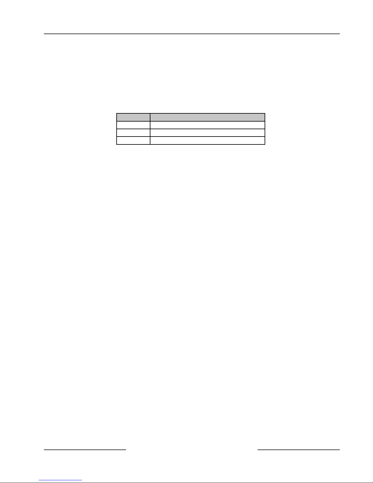
1.1 Organization
This guide is divided into 16 sections with seven appendices. Table 1 contains a summary of each section.
Section
1.0
2.0
3.0
4.0
5.0
6.0
7.0
8.0
9.0
10.0
11.0
12.0
13.0
14.0
15.0
16.0
Appendices A: Approved Applications and Compliance Guide
Introduction
Overview
specifications, standard and new features.
Installation
the panel and ready for programming.
Power Supply
instructions for correcting problems with them.
Power Outputs
output and built-in siren driver.
Telephone Connections
On-Board Sensor Loops
on the D6412/D4412.
Off-Board Sensor Loops
including detailed instructions for connecting the DX2010 Point Expansion Module.
On-Board Outputs
Off-Board Outputs
including detailed instructions for connecting the DX3010 OctoOutput Module.
Arming Devices
zone controls.
SDI Devices
that connect to the D6412/D4412’s data terminals (SDI bus).
Installer’s Keypad and Installer Mode
the Installer’s Mode.
Installation Label
terminal.
Terminal Quick Reference
terminal.
Troubleshooting
B: SDI Address Chart
- This section.
- Overview of the D6412/D4412 Control Panel, including operational
- Basic installation instructions, including everything needed to power up
- Information about the primary and secondary power sources and
- Information about the available powered outputs, including the alarm
- Information about connecting the phone line.
- Information about the eight on-board sensor loops available
- Information about available off-board sensor loops,
- Information about the four on-board programmable outputs.
- Information about available off-board programmable outputs,
- Information about command centers, keyswitches, and independent
- Descriptions and installation instructions for various optional modules
- Copy of the installation label found inside the D6412/D4412
- Chart providing a short description of each D6412/D4412
- Potential solutions to a variety of commonly encountered problems.
Description
- Information for using an Installer’s Keypad and
T able 1: D6412/D4412 I nstallation Guide Organization
D6412/D4412 Operation and Installation Guide
Page 7© 2003 Bosch Security Systems 45349E
D6412/D4412
Introduction
1.2 Other Literature Referenced
Throughout this guide, references are made to other documentation. Review the documents in the table below for a complete
description of the panel. Part numbers are included for ordering purposes.
Document Name Part Number
D6412/D4412 Program Entry Guide 45351
D6412 Program Record Sheet 45350
D4412 Program Record Sheet 50485
D6412/D4412 TSN: Smoke Detector Compatibility 46928
User's Guide for LED Command Centers 46840
User's Guide for Text Command Centers 46841
D6412 Firmware Release Notes 46929
D4412 Firmware Release Notes 50482
DX2010 Installation Guide 49533
DX3010 Installation Guide 49529
DX4010 Installation Guide 49539
Table 2: Other Literature Referenced
1.3 Documentation Conventions
These conventions are intended to call out important features, items, notes, cautions, and warnings that the reader should be
aware of in reading this document.
1.3.1 Type Styles Used in this Guide
T o help iden tify important items in the text, the following type styles are used:
Bold text Usually indicates selections that you may use while programming your
panel. It may also indicate an important fact that should be noted.
Bold italicized Used to denote notes, cautions, and/or warnings.
Italicized text Refers the user to another part of the guide or to another document entirely.
Courier text Indicates what may appear on the command center/keypad or in a report
received at the central station receiver .
[Text in bracket s] Indicates to the user that a specific key should be pressed. Example: Press
[Cmd] to exit this feature.
1.3.2 Tips, Important Notes, Cautions, and Warnings
Throughout this document, helpful tips, important notes, cautions and warnings are presented for the reader to keep in
mind. These appear different from the rest of the text as follows;
Important Notes - should be heeded for successful operation and programming. Also, tips and shortcuts may be
included here.
Caution - These caution the operator that physical damage to the panel and/or optional equipment may occur.
W arning - These warn of the possibility of physical damage to the operator and/or equipment.
D6412/D4412 Operation and Installation Guide
Page 8 © 2003 Bosch Security Systems45349E

D6412/D4412
Introduction
1.4 FCC Notice
1.4.1 Part 15
This equipment has been tested and found to comply with the limits for a Class B digital device, pursuant to Part 15 of the
FCC rules. These limits are designed to provide reasonable protection against harmful interference when the equipment is
operated in a commercial environment.
This equipment generates, uses, and can radiate radio frequency energy and, if not installed and used in accordance with this
instruction guide, may cause harmful interference to radio communications.
Operation of this equipment in a residential area is likely to cause harmful interference, in which case the user is required to
correct the interference at his own expense.
1.4.2 Part 68
This equipment complies with Part 68 of FCC rules. A label contains, among other information, the FCC registration
number and ringer equivalence number (REN). If requested, this information must be provided to the telephone company.
The Bosch Security Systems D6412/D4412 Control Panel is registered for connection to the public telephone network using
an RJ38X or RJ31X jack.
The ringer equivalence number (REN) is used to determine the number of devices that may be connected to the telephone
line. Excessive RENs on the telephone line may result in the devices not ringing in response to an incoming call. In most, but
not all areas, the sum of the RENs should not exceed five (5). To ascertain of the number of devices that may be connected to
the line, as determined by the RENs, contact the telephone company to determine the maximum REN for the calling area.
If the D6412/D4412 Control Panel causes harm to the telephone network, the telephone company notifies you in advance. If
advance notice isn’ t practical, the telephone compan y notifies the customer as soon as possible. Also, you are advised of your
right to file a complaint with the FCC if you believe it is necessary.
The telephone company may make changes in its facilities, equipment, operations, or procedures that could affect the
operation of the equipment. If this happens, the telephone company provides advance notice so you can make the necessary
modifications for maintaining uninterrupted service.
If trouble is experienced with the D6412/D4412 Control Panel, please contact Bosch Security Systems Customer Service for
repair and/or warranty information. If the trouble is causing harm to the telephone network, the telephone company may
request that you remove the equipment from the network until the problem is resolved. User repairs must not be made, and
doing so voids the user’ s warranty .
This equipment cannot be used on public coin service provided by the telephone company . Connection to Party Line service
is subject to state tariffs. (Contact your state public utilities commission for information.)
FCC Registration Number: ESVMUL-46531-AL-E
Ringer Equivalence: 0.1B
Service Center in USA: National Repair Center
130 Perinton Parkway
Fairport, NY 14450-9199 USA
(800) 289-0096 ext. 4220
D6412/D4412 Operation and Installation Guide
Page 9© 2003 Bosch Security Systems 45349E
D6412/D4412
Overview
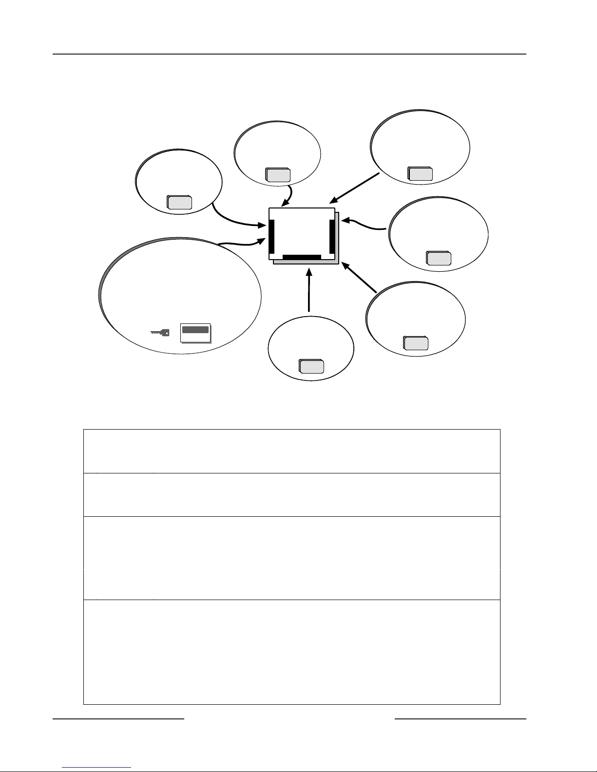
2.0 Overview
DX2010
Point Expansion Module
DX3010
Octo-Output Module
RF3224 Premises
RF Receiver
(up to 4 RF keypads
and 32 keyfobs)
Use command c enters and/or key switches to
arm the panel by area. Each area can have its
own account number or areas can be grouped
together with a common account number.
Points of protection are assigned to areas.
2.1 Specifications
Voltage Input
Primary:
Secondary:
Current Requirements
Panel:
Power Outputs
Continuous:
Note: Up to 400 mA at 11. 5 VD C to 12.4 VDC for UL Listed burglary applications, 120 mA for Fire and
Battery Discharge/Recharge Schedule
Combined Burglary/Fire (continuous supply) total for all device s and outputs.
Alarm
Power:
Discharge
Cycle:
Recharge
Cycle:
Control Panel
8 On-Board
Sensor Loops
4 On-Board
Outputs
DX3020 Module
Provides control for
X-10 modules.
(for connection of serial printer
D8132 Modules provide
additional power for command
centers and o ther powered
DX4010
Serial Interface Module
or other RS-232 devic e) .
devices.
Figure 1: System Configuration
18 VAC 22 VA class 2 plug-in transformer CX4010 (D1825)
12 VDC, 7 Ah sealed lead acid rechargeable battery or 12 VDC, 18 Ah sealed lead acid
rechargeable battery.
100 mA
See Appendix : Approved Applications Compliance Guide for the current requirements of other
system components.
Up to 600 mA maximum at 11.5 VDC to 12.4 VDC (continuous supply) total for all devices
and outputs for non UL a pplications.
400 mA for Fire and combined Fire/Burglary; 1500 mA for UL Burglary; 1850 mA for other
(not investigated by UL ). Applies to all four outputs combined. See the Outputs section of the
D6412/D4412 Program Entry Guide (P/N: 45351).
AC Off: Command centers indicate trouble. AC Fail Report sent as programmed.
•
13.8 VDC: Charging Float Level.
•
12.1 VDC: Low Battery trouble at command centers.Low Battery Report as prog rammed.
•
10.2 VDC: Panel shuts down as voltage falls below 10.2 VDC.
•
AC On: Panel restarts, battery charging begins, AC Restoral Report sent as programmed, AC
•
trouble clears from command centers.
13.0 VDC: Battery Restoral Reports sent, battery trouble clears from command centers.
•
3.8 VDC: Battery float charged.
•
D6412/D4412 Operation and Installation Guide
Page 10 © 2003 Bosch Security Systems45349E

D6412/D4412
Overview
Minimum
Operating
Voltage
SDI Bus (Data)
Telephone
Connections
Environmental
Arming Stati o ns
Compatible
Enclosures
Compatible
Accessories
Control Panel
Configurations
10.2 VDC
12 VDC nominal. 305 m (1000 ft.) of 22 AWG (0.8 mm) cable.
RJ31X or RJ38X jack can be interfaced with panel
Temperature: 0°C to +50°C (+32° to +122°F)
Relative Humidity: 5% to 8 5% at +30°C (+86°F ) non-condensing
D625 VF Text Command Center
•
D623 LCD Text Command Center
•
D621 LED Command Center
•
Keyswitch
•
D2203 Universal Enclosure (included with panel), D8103 Universal Enclosure, D8109 Fire
Enclosure, D8108A Attack Resistant Enclosure.
Note: When ordering a compatible enclosure, order the D6412M (includes the mounting skirt
and the D6412LC) or the D4412M (includes the mounting skirt and the D4412LC). In addition,
order the CX4010 transformer.
D621 LED Command Center
•
D623 Text Command Center, LC D Display
•
D625 Text Command Center, Vacuum Fluorescent Display
•
DX2010 (D9528) Point Expansion Module
•
DX3010 (D9529) Octo-Output Module
•
DX3020 (X7410I) Module (not investigated by UL)
•
DX4010 (D9533) Serial Output Module (not investigated by UL)
•
DX8010 Telephone Command Module (not investigated by UL)
•
DS RF3224 Premises RF Receiver
•
DS RF3332/3334 Keyfob (not investigated by UL)
•
DS RF3341 Keypad (not investigated by UL)
•
Programming Key (PK32)
•
D6412 - Complete control panel assembly in the D2203 Universal Enclosure. A CX4010
•
Transformer is su pplied.
D6412LT - Complete control panel assembly in the D2203 Universal Enclosure. A CX4010
•
Transformer must be ordered separately.
D6412LC - Complete control panel assembly without an enclosure or transformer. A
•
CX4010 Transformer must be ordered separately.
D6412M - Complete control panel assembly with a mounting skirt for the compatible
•
enclosure. A CX4010 Transformer must be ordered separately. See Compatible Enclosures
in this table for compatibl e enclosure alternatives.
D4412 - Complete control panel assembly in the D2203 Universal Enclosure. A CX4010
•
Transformer is su pplied.
D4412LT - Complete control panel assembly in the D2203 Universal Enclosure. A CX4010
•
Transformer must be ordered separately.
D4412LC - Complete control panel assembly without an enclosure or transformer. A
•
CX4010 Transformer must be ordered separately.
D4412M - Complete control panel assembly with a mounting skirt for the compatible
•
enclosure. A CX4010 Transformer must be ordered separately. See Compatible Enclosures
in this table for compatibl e enclosure alternatives.
D6412/D4412 Operation and Installation Guide
Page 11© 2003 Bosch Security Systems 45349E

D6412/D4412
I
T
I
T
Overview
2.2 SIA Control Panel Standard
The D6412/D4412 utilizes features within the SIA Control Panel Standard, Features for False Alarm Reduction,
SIA CP-01-1994.02 (R2000.01). SIA features are noted in the D6412/D4412 Program Entry Guide (P/N: 45351). The standard
is available through:
Security Industry Association (SIA)
635 Slaters Lane, Suite 110
Alexandria, Virginia 22314
You can e-mail requests for standards to: Standards@SIAOnline.org.
2.3 Standard Features
2.3.1 Points
The Bosch Security Systems D6412 Control Panel provides up to 40 separate points of protection (24 for the D4412 panel).
Point programming parameters determine the panel’ s response to open and shorted co nditions on the point’ s sensor loop.
Points are programmed individually with several options to customize the protection to your installation. There are eight
sensor loops available on the panel (for on-board points). Off-board point locations can be standard wired sensor loops
(DX2010 Point Expander) or premises RF transmitters (premises RF receiv er is required). The 40 points of protection for the
D6412 (24 points for the D4412) can be located on any combination of wired and RF locations.
2.3.2 Areas and Accounts
The system supports up to four separate areas for the D6412 and up to two separate areas for the D4412. You can assign all
points to a single area or spread them out over a maximum of two or four areas, model dependent.
You arm and disarm the panel by are. You can arm and disarm several areas with one function. You can also assign a
passcode an authority level that allows a user to arm an area from a remote command center in another area. Assigning each
area its own account number creates four (D6412) or two (D4412) separate accounts in one panel. Assigning the same
account number to different areas groups them together in a single account.
Area options include: exit tone and delay , separate fire and burglary outputs, and auto opening and closing skeds. A rea 1 can
be programmed as a common area. A “First to Open, Last to Close” arming feature is available.
2.3.3 Communicator
The panel uses a built-in digital communicator to send reports to the receiver. It transmits reports in either Modem IIIa²,
Contact ID, or Pager format.
Only the following central station receivers support the panel’s Modem IIIa² fo rmat:
• D6600 with CPU v01.01.03 (or higher)
• D6500 with D6511 MPU v1.05 (or higher)
The D6500 with D6510 MPU does not support the panel’s M odem IIIa2 Format.
MPORTAN
The panel connects to an RJ31X jack for phone line seizure. Connection to the RJ31X complies with FCC regulations for
using the public telephone network. You can pr ogram the panel to route reports to one of two routing destinations.
The system has routing capabilities that allow you to direct groups of system event reports and individual point reports to
two different routing destinations. The reports can be routed to either destination, both destinations, or to Destination 2
only on failure of Destination 1.
Each routing destination can be programmed with two phone numbers.
Check panel communications at least once annually (from panel to central station) to verify the panel is
communicating properly in the selected reporting format.
MPORTAN
D6412/D4412 Operation and Installation Guide
Page 12 © 2003 Bosch Security Systems45349E
D6412/D4412
Overview
2.3.4 Command Centers
You can connect a maximum of eight, fully-supervised command centers to the system. The available power affects the total
number of command centers you can connect without providing an auxiliary power supply.
The panel transmits a Serial Device Trouble R eport, SDI MISSING in the Mode m IIIa² fo rmat or Sys Peripheral
Trouble in the Contact ID format, if it loses communication with a command center . Table 3 shows the command centers
compatible with the panel. Refer to Command Center in the D6412/D4412 Program Entry Guide (P/N: 45351) for complete
details on programming command center options.
Model Display
D621 16-Point LED
D623 Two lines of 16 charact er s, LC D
D625 Two lines of 16 charac t er s, v acuum fluorescent
Table 3: Compatible Command Centers
2.3.5 Keyswitch
You can arm and disarm any of the available areas with maintained or momentary closure devices such as keyswitches. P oint
programming determines loop responses and which area a keyswitch controls. Sub-control units (D279) can arm and
disarm individual points.
2.3.6 Alarm Event Memory
The system uses alarm event memory to store alarm events for each area. You can view the area alarm events at a command
center assigned to the area. The panel clears the area’s alarm event memory and starts storing new alarm events when you
turn the area on.
2.3.7 Event Log
The system stores 254 events from all areas in its event log. All events can be stored even if the panel does not send a report
for them. You can view the log at a text co mmand center (the D623 for example), print it locally using the DX4010 Serial
Interface Module and a serial printer , or upload it to the Remot e A ccount M anager (RAM IV).
See Appendix B in the D6412/D4412 Program Entry Guide (P/N: 45351) for a listing of log events and how to view them.
2.3.8 EMI/Lightning Transient Protection
The panel maintains Bosch Security Systems high level of quality and field dependability . Its design significantly reduces
electromagnetic interference and malfunction generally caused by lightning.
2.3.9 Programming
Use either a text keypad or the Remote Account Manager (RAM IV) to program the panel. Refer to the D6412/D4412
Program Entry Guide (P/N: 45351) for programming options.
2.3.10 Other Features
The panel has many programmable features. A short list of some of the features follows.
• Supervision of AC (primary power), battery (secondary power), SDI bus devices (keypads, point expanders,
programmable output modules, alternate communication modules, etc.), central processing unit (CPU), and the
telephone line (voltage only).
• Aut omatic syste m test reports
• Remote access for programming, diagnostics, and log uploads using the Remote Account Manager (RAM IV)
• Fire Alarm Verification
• Up to twenty (D6412) or twelve (D4412) Programmable Outputs, including a supervised siren driver
• Skeds (scheduled events)
Complete details on all the features can be found in the D6412/D4412 Program Entry Guide (P/N: 45351).
D6412/D4412 Operation and Installation Guide
Page 13© 2003 Bosch Security Systems 45349E
D6412/D4412
Overview
2.3.11 Control Panel Assembly
The Bosch Security Systems control panel is shipped from the factory pre-assembled. You should receiv e the following parts
with your panel.
Literature Package
D6412
Control Panel
D6412/D4412 Installat ion Guide (P/N: 45349)*
D6412 Program Record Sheet (P/N: 45350)*
D6412/D4412 Program Entry Guide (P/N: 45351)*
D6412 Release Notes (P/N: 46929)
D6412/D4412 TSN: Smoke Detector Compatibility (P/N: 46928)*
D6412 Specifications Sheet (P /N: 48392)*
D4412
Control Panel
D6412/D4412 Installat ion Guide (P/N: 45349)*
D4412 Program Record Sheet (P/N: 50485)*
D6412/D4412 Program Entry Guide (P/N: 45351)*
D4412 Release Notes (P/N: 50482)
D6412/D4412 TSN: Smoke Detector Compatibility (P/N: 46928)*
* This literature is available in a separate literature package for dealers.
Assembly
• Printed Circuit Board (PCB)
• CX4010 transformer (order separately when ordering the D6412LC, D4412LC, D6412LT, D4412L T, D6412M,
or D4412M)
• T w o mounting clips
• Two #6 x 3/4 in. screws
• Eight 2.2 kΩ EOL resistors (eight-pack [P/N: 47819], single resistor [P/N: 25944B])
• Eight 3.65 kΩ point-doubling EOL resistors (eight-pack [P/N: 47821], single resistor [P/N: 38130B])
• One 2.21 kΩ fire EOL resistor (P/N: 25899)
• Two 14 in., 18 AW G (1.2 mm), c olor-c oded battery leads
• Three PCB support standoffs (P/N: 30503B)
Ordered Separately
Order the following to complete a basic eight-point installation.
• Command center (or keyswitch)
• D118 Speaker (for PO2 in supervised configuration) D118 not investigated by UL.
• D126 Battery
• D164 Phone Cord
Configured packages are also available. Please consult your Bosch Security Systems Product Catalog.
2.3.12 Listings and Approvals
Fire
CSFM
Burglary
U n d erwriters L ab o ra to ries
H o u seh o ld F ire Wa rn in g UL9 85
App roved by the Califo rn ia State Fire Marshal for Co n trol Un its (Hou sehold)
U n d erwriters L ab o ra to ries
- UL1023 H ousehold
- UL365 Police Connect
- UL609 Local
- UL1076 Proprietary
- UL609 Central Station
- UL609 D igital Alarm
D6412/D4412 Operation and Installation Guide
Page 14 © 2003 Bosch Security Systems45349E

D6412/D4412
I
T
Installation
3.0 Installation
3.1 Before You Begin
This section contains a general installation procedure. It refers to other sections of the guide for detailed instructions.
Bosch Security Systems recommends you review this guide and the D6412/D4412 Program Entry Guide (P/N: 45351) before
you begin installation to determine the hardware and wiring requirements for the features you want to use.
As you read through this guide, have the following documents at hand:
• D6412 Program Record Sheet (P/N: 45350) or D4412 Program Record Sheet (P/N: 50485)
• User’ s Guide (Text Command Center [P/N: 46841]; LED Command Center - 46840). A co ndensed version of the
User’s Guide is found in the D6412/D4412 Program Entry Guide (P/N: 45351).
• Installation guide for each command center model you intend to install.
Before you begin installing the panel, you should be familiar with keypad programming or the Remote Account Manager
(RAM IV).
3.2 Enclosure Options
The D2203 Enclosure is supplied with the standard D6412/D4412 Control Panel. To mount the D6412 in one of the Bosch
Security Systems enclosures listed below, ord er the D6412M version (order the D4412M version for the D4412).
• D8103 Universal Enclosure (gray)
• D8109 Fire Enclosure (red)
• D8108A Attack Resistant Enclosure (gray)
The “M” version substitutes a D2202 M ounting Skirt for the D2203 enclosure allowing installation in the other enclosures.
“M” does not include a transformer . Order a CX4010 separately . R efer to A ppendix A: Approved A pplications Compliance
Guide to determine if your application requires a specific enclosure.
Mount the enclosure in the desired location.
3.3 Premises Wiring
Run the necessary wiring throughout the premises and route the wires into the enclosure.
Electro Magnetic Interference (EMI) may cause problems. EMI may occur if you install the system or run system
wires near the following:
MPORTAN
If you think that EMI may be a problem, use shielded cable. The drain wire for the shielded cable must have continuity from
the earth ground terminal on the panel to the end of the wire run. If continuity is not maintained, the shielded cable may
aggravate potential noise problems rather than eliminate them.
Connecting the drain wire to ground at any place other than the earth ground terminal may also produce problems. If you
cut the drain wire to install devices, be certain to splice it together. Carefully solder and tape all splices.
• Computer network system
• Electrical lines, fluorescent fixtures or telephone cabling
• Ham radio transmitter site
• Heavy machinery and motors
• High voltage electrical equipment or transformers
• PBX telephone system
• Public service (police, fire departments, etc.) using radio communications
• Radio station transmitter site or other broadcast station equipment
• Welding shop
D6412/D4412 Operation and Installation Guide
Page 15© 2003 Bosch Security Systems 45349E
D6412/D4412
Installation
3.4 Installing the Assembly
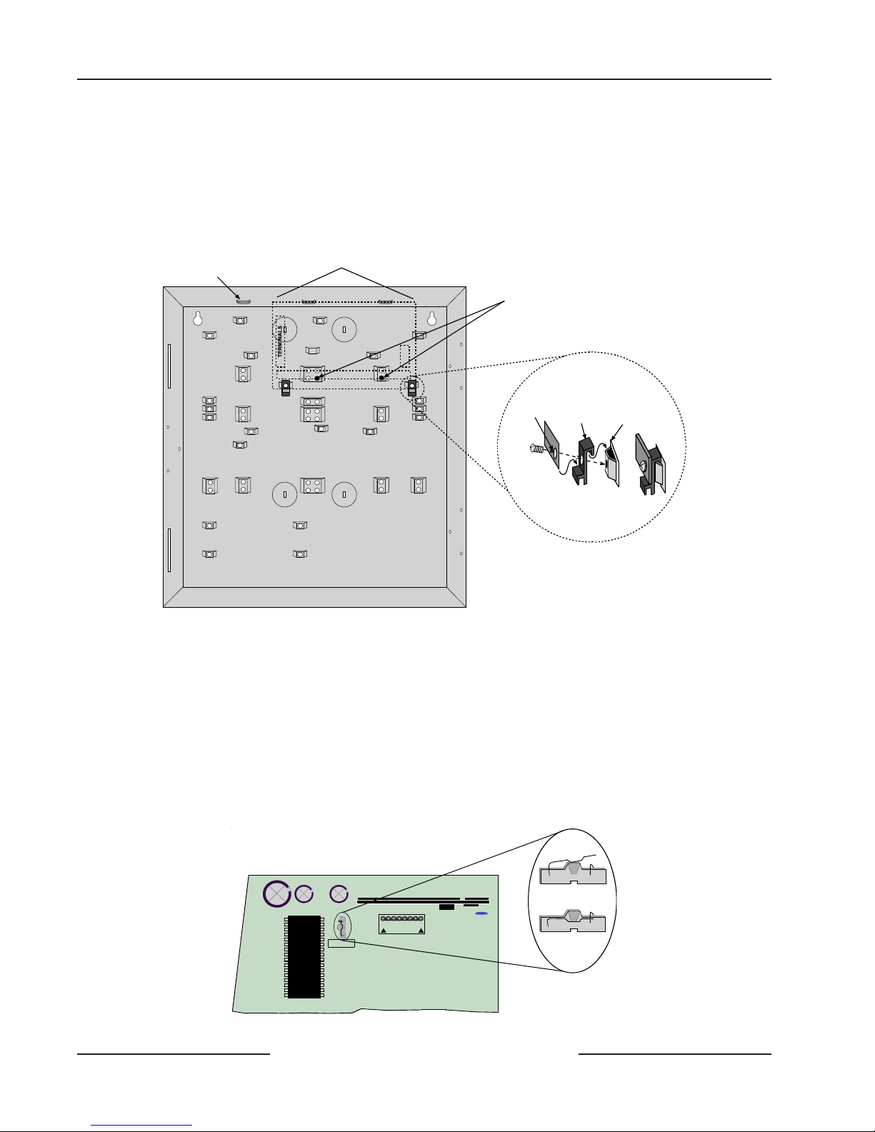
1. Place the panel mounting clips on the appropriate standoff in the enclosure (see Figure 2).
2. Slide the panel into the slots at the top of the enclosure and then secure it with the two screws provided
(see Figure 2).
3. Connect earth ground to the panel before making any other connections (see Section 3.4.1 Connecting
Earth Ground).
Mounting Slots
D6412/D4412 PCB Location
D6412/D4412 BOARD
TERMINALS
Install the PCB support standoffs here (P/N: 30503B)
Corner of
D6412/D4412
Mounting
PCB
Clip
Mounting Clip Assembly
Enclosure
Standoff
=
Figure 2: Enclosure Mounting
3.4.1 Connecting Earth Ground
T o help pr event damage from electrostatic charges or other transient electrical surges, connect the system to earth ground
before making any other connections. A grounding rod or cold water pipe are recommended earth ground references.
Do not use telephone or electrical ground for the earth ground connection. Use 14 to 16 AW G (1.8 mm to 1.5 mm) wire
when making the connection. Use only the earth ground terminal. Do not connect any other panel terminals to earth
ground.
3.4.2 Closing the Installer Switch
Closing the Installer Switch disables the panel (see Figure 3). System reporting is disabled and the system cannot be armed. A
system trouble shows at all keypads.
D6412/D4412 Operation and Installation Guide
JP1
AUXILIARY
Installer
Figure 3: Installer Switch
Page 16 © 2003 Bosch Security Systems45349E
INSTALLER SWITCH
NORMAL (OPEN)
INSTALLER SWITCH
LOCKED (CLOSED)

D6412/D4412
Installation
Opening the Installer Switch from the closed position resets the panel. The panel resets all its timers, counters, indexes, and
buffers. Any points that restore after a reset is performed do not generate Restoral Reports.
Leaving the Installer Switch in the closed position lets you power up the panel and charge the battery as you install the
detection devices and command centers.
3.5 Finishing the Installation
3.5.1 Earth Ground and Installer Switch
First, make the earth ground connection and close the Installer Switch if you have not already done so.
T o reduce the occurrence of false alarms upon toggling of the Installer Switch, the panel ignores all point faults while the
devices stabilize during the setup process. The panel’s start-up process tak es appro ximately 60 sec. to co mplete. It occurs at
power-up and when the panel resets (Installer Switch OPEN). See Section 3.5.7 Power Up and Section 13.3.10 Exiting the
Installer’s M enu for more information. During this period, a screen showing the panel model number (D6412 or D4412),
firmware revision number , and a “Please W ait...” message appears for appro ximately 10 sec onds.
D6412 Rev
Please Wait...
3.5.2 Charge the Battery as You Finish
Connect the battery and then the transformer so that the panel can charge the battery as you finish the installation. See
Section 4.0 Power Supply for instructions.
Self-Diagnostics at Power U p and R e set: The system performs a series of self-diagnostic tests of its hardware, software, and
program at power up and at reset. They take about 60 sec. to co mplete. Command centers may display “ S yst em Fault ” and
sound during the power up and reset interval.
If the panel fails any of the tests, a system trouble message appears at the command centers.
T ouch the Earth Ground Terminal First: To discharge any static charge you may be carrying, alwa ys touch the panel’s earth
ground terminal before beginning work on the panel.
3.5.3 Install and Wire Detection Devices
Install and wire detection devices and command centers at their locations throughout the premises. Do not make the
connections at the panel end of the wiring yet.
Section 7.0 On-Board Sensor Loops contains instructions for wiring the on-board point locations to detection devices. Section
11.0 Arming Devices contains instructions for wiring the command centers.
Instructions for wiring the off-board point locations are found in the instructions packaged with the point expansion
devices.
3.5.4 Install Modules
1. P ower Down First: P ower do wn the unit by unplugging the transformer and disconnecting the battery.
Bosch Security Systems recommends powering down the unit when installing modules or when making
wiring connections to the panel.
2. Install and wire any modules required for your installation as described in the module’s installation
instructions.
Instructions for the DX2010 Point Expansion Module and the DX3010 Output Expansion Module are included in this guide.
See Section 8.0 Off-Board Sensor Loops for DX2010 instructions and Section 10.0 Off-Board Outputs for DX3010 instructions.
3.5.5 Make the Telephone Connections
If you are connecting the panel to a ground start phone system, you need to install a D133/D134 Relay . See Section 6.0
T elephone Connections for complete instructions.
3.5.6 Connect the On-Board Points and Command Centers
Connect the on-board points and command center wiring to the system. See Section 7.0 On-Board Sensor Loops and Section
11.0 Arming Devices for instructions.
X.XX
D6412/D4412 Operation and Installation Guide
Page 17© 2003 Bosch Security Systems 45349E

D6412/D4412
Installation
3.5.7 Power Up
Reconnect the battery and then plug in the transformer.
Leave the Installer Switch in the CLOSED position for now . (See Figure 3). The following sequence of events occurs:
1. “System Fault” appears on the text command center(s) and all command centers emit a single tone for
approximately 10 seconds.
2. A screen showing the panel model number (D6412 or D4412), firmware revision number and a “Please
Wait... ” message appears for approximately 10 seconds.
3. “Trouble! Press Cmd 4 to View” appears. Press the [CMD] and [4] keys. A new message appears:
Date/Time lost! Press 5 to set.” Press the [5] key to enter the Dat e/Time window and set accordingly .
To reduce the occurrence of false alarms upon panel power -up (or restoration of power after a complete
loss of primary and secondary power), the panel ignores all point faults for approximately 60 sec. while
the devices stabilize. This process is part of the panel’s start-up process, and it occurs at pow er -up. This
60-sec. period begins when the “Please Wait... ” screen appears.
The “Trouble! Press Cmd 4 to V iew” message reappears, indicating that the Installer Switch is closed. To
return the system to normal (disarmed, no fault/trouble conditions), open the Installer Switch (unless
you are ready to program the panel).
D6412 Rev
Please Wait...
3.6 Programming the Panel
If you have not created a program for the panel, review the D6412/D4412 Program Entry Guide (P/N: 45351). Make certain
you have all the required accessory modules installed for the features you want to use.
Note: The Installer Switch must be in the closed position to program the panel from a keypad.
You can enter your custom program at a text keypad, or send it to the panel from the R emo te A cc ount Manager (RAM IV).
There is a connector provided on the panel for quick connection of an installer’s k eypad to the system for programming. See
Section 13.0 Installer’s K eypad and Installer Mode for complete instructions for the installer keypad.
After you finish programming, move the Installer Switch to the open position. If the unit is programmed for reporting, the
panel transmits a Reboot Report to the receiver .
X.XX
3.7 Check for Fire Alarm Verification
You must check the Alarm Verification Box in the lower left corner of the label if you programmed Point 1 for Fire with
V erification. See Point Index in the D6412/D4412 Program Entry Guide (P/N: 45351). R efer to Section 14.0 Installation Label
for the location of the Alarm Verification Box on each installation label.
3.8 Testing the System
After finishing the installation and programming of the panel, make a complete functional test of the system. T est the panel
and all devices for proper operation. Test after you first program the panel and after any subsequent programming session.
W alk Test: U se the Walk Test (Cmd 44) or the point test available in the Installer Mode to perform a complete test of the
panel. See Section 13.0 Installer’s K eypad and Installer Mode.
If you test a device and the panel does not respond, there may be a problem with the device, wiring, a module setting, or
programming for the point.
Clear After T est: To clear the event memory and report buffer , mom entarily close the Installer Switch. E vents sto red in the
panel’s event log are not clear ed.
D6412/D4412 Operation and Installation Guide
Page 18 © 2003 Bosch Security Systems45349E
D6412/D4412
I
T
Power Supply
4.0 Power Supply
4.1 Primary Power
4.1.1 Primary (AC) Power Circuit
An 18 VAC, 22 VA internally fused transformer (Bosch Security Systems CX4010) is the primary power source. The A C
power circuit provides 700 mA of rectified AC pow er . The panel reserves 100 mA of this power for inte rnal operations,
leaving 600 mA for powered devices.
Transient suppressors and spark gaps protect the circuit from power surges. This protection relies on the panel’s earth
ground connection. Make sure you connect the earth ground terminal to a proper ground. See Section 3.4.1 Connecting
Earth Ground.
The system indicates an AC pow er failure when the power at the t erminals marked “18 VAC” is interrupted. P ow er must be
missing for 120 sec. before the panel acknowledges the failure. Po wer must be maintained at those terminals for 120 sec.
before the panel acknowledges the restoral of power .
4.1.2 Installing the Transformer
Shorting the terminals for prolonged periods of time may cause permanent damage. Connect the transformer to the
panel terminals before plugging it into the power source.
CAUTION
Bosch Security Systems recommends that you always connect the battery first and then plug in the transformer. See
MPORTAN
Use 18 AW G (1.2 mm) (minimum) wire to connect the transformer to the panel. Wire length should be kept as short as
possible. The maximum length is 15.2 m (50 feet).
AC wiring can induce both noise and low level voltage into adjacent wiring. Route phone and sensor loop wiring away from
any AC conductors, including the transformer wire. Route data wiring away from AC and phone wiring.
Only plug the transformer into an unswitched, 120 VAC, 60 Hz po wer outlet. Secur e the transformer to the outlet with the
screw provided.
Section 4.2.2 Installing the Battery for more information.
4.2 Secondary Power
4.2.2 Installing the Battery
Place the battery upright in the base of the enclosure. Locate the red and black leads supplied in the literature pack. Push one
connector on the black battery lead to panel’s “ Batt-” c onnector , and then push the lead’ s other connector to the negative (-)
side of the battery. Push one connector on the red battery lead to panel’ s ‘Batt+’ co nnector , and then push the lead’ s other
connector to the positive (+) side of the battery.
High Current Arcs P ossible: The positive (red) battery lead and the panel’s “Batt+” connector can create high
current arcs if shorted to terminals or the enclosure. Use caution when working with the positive lead and the
panel’s “Batt +.” Alw ays disconnect the positive (red) lead from the battery before removing it from the panel.
4.2.3 Replacement
Bosch Security Systems recommends battery replacement every three to five years under normal use. Exceeding the
maximum output ratings, or installing the transformer in an outlet that is routinely switched off, causes heavy discharges.
Routine heavy discharges can lead to premature battery failure. Rec ord the date of installation directly on the battery.
4.2.4 Battery Supervision
When the battery drops to 12.1 VDC, the panel (if programmed for power supervision) transmits a Battery Low Report.
If the battery is missing or shorted and the panel is programmed for power supervision, it transmits a Battery Missing
Report.
When battery voltage returns to 13.0 VDC, the panel (if programmed for power supervision) transmits a Battery Restoral
Report.
D6412/D4412 Operation and Installation Guide
Page 19© 2003 Bosch Security Systems 45349E
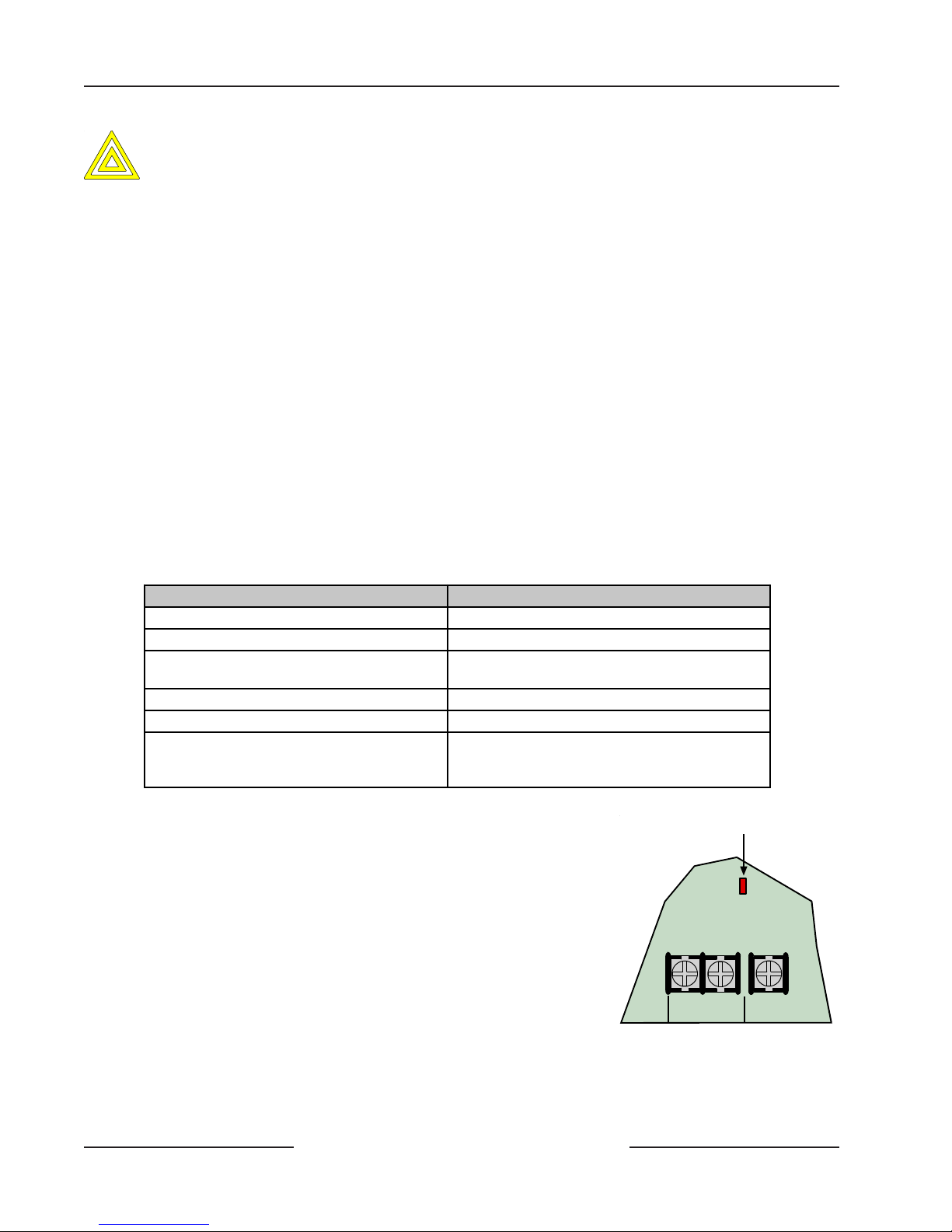
D6412/D4412
Power Supply
Investigate low battery reports immediately: If primary (AC) power is off and the discharge continues, the panel
becomes inoperative when the battery voltage drops below 10.2 VDC.
CAUTION
4.2.5 Battery Charging Circuit - Float Charge
The float voltage for the battery charging circuit is 13.5 VDC to 13.9 VDC at a maximum current of 1.4 A.
4.2.6 Battery Discharge/Recharge Schedule
Discharge Cycle
• AC Off: Command centers indicate trouble. AC Fail Report sent as programmed.
• 13.8 VDC: Charging float level
• 12.1 VDC: Low battery trouble at command centers. Low Battery Report as programmed.
• 10.2 VDC: Panel shuts down as voltage falls below 10.2 VDC
Recharge Cycle
• AC On: Panel restarts, battery charging begins, AC Restoral Report sent as programmed, AC trouble clears from
command centers.
• 13.0 VDC: Battery restoral reports sent, battery trouble clears from command centers
• 13.8 VDC: Battery float charged.
4.2.7 System Status LED
The System Status LED shows system status, including pow er supply status as described in Table 4. See Figure 4 for the
location of the LED on the panel.
System Status LED Display
System Normal
Battery Missing
AC Missing
Phone Ringing
Phone Line Seized (panel using phone line)
On for 50 ms; Off for 1 sec.
Off for 200 ms; On for 1 sec.
Off for 200 ms; On for 200 ms
Off for 200 ms; On for 1 sec.
Flickers for 1 sec. as each ring is detected.
On solid.
Off for 200 ms; On for 200 ms
Shut Down (system voltage below 10.2 VDC)
Off for 200 ms; On for 200 ms
Off for 200 ms; On for 1 sec.
Table 4: System Status LED Description
4.3 External Power Supply
The external power supply (not supplied) is not intended to provide power to
indicating devices for burglary and fire applications.
• Burglary Applications use a UL603 Listed burglar alarm power supply
with an operating voltage range of
11.8 VDC to 12.4 V DC for Bank Safe/Vault applications (72 hrs. of
standby battery required).
• Fire Applications use a UL1481 Listed power supply operating voltage
range of 11.8 VDC to 12.4 VDC for fire applications.
System Status LED
L-2Com L-3
Figure 4: System Status LED
D6412/D4412 Operation and Installation Guide
Page 20 © 2003 Bosch Security Systems45349E

D6412/D4412
I
T
Power Outputs
5.0 Power Outputs
5.1 Circuit Protection
Three self-resetting thermal circuit breakers protect the panel from short circuits on both the continuous and programmable
power outputs. If the panel is programmed for power supervision and a short is sustained on one of the power outputs, the
panel transmits a Battery Low or Battery Missing Report.
One breaker protects A uxiliary Po wer and the Installer’ s K eypad Connector; a short on one disrupts power to the other .
One breaker protects the Alarm P ower Output (Alrm + Terminal) and one breaker protects the battery .
5.2 Available Power
5.2.1 Auxiliary Power
Use the auxiliary power terminals to powe r devices requiring continuous power . See Section 14.0 Installation Label and
Section 15.0 T erminal Quick Reference for the location and description of these terminals.
5.2.2 Installer’s Keypad Connector
Use this connector t o connect an installer’ s keypad to the panel for programming and diagnostics.
5.2.3 Alarm Power
Provides positive 12 VDC for Programmable Output 2 (PO2 ) when it is configured as a siren driver and Programmable
Output 1 (PO1) when it is configured as the alarm output.
5.3 Continuous Power Output
5.3.1 Continuous Current Draw
The continuous current draw for powered devices connected to the A ux P ower terminals, Installer’s K eypad Connector , and
Outputs PO1 to Programmable Output 4 (PO4 ), when programmed for continuous output, are restricted as follows:
• 120 mA for Fire and Combined Fire/Burglary systems
• 400 mA for UL Burglary systems
• 600 mA for other applications (not investigated by UL)
5.4 Alarm Power
5.4.1 Available Power
The system combines the 600 mA of primary power produced by the power supply with the secondary power source (the
battery) to produce a total of 1.5 A of alarm power at 11.5 VDC to 12.4 VDC. Alarm power is available at the Alrm +
terminal. The panel uses PO1 through PO4 to activate Alarm power (see Section 5.5 Output Programming).
Fire systems are prohibited from using the battery for determining alarm power. Use the Fire S ystem Power
Formula below to calculate the current available for fire and combined fire/burglary systems.
MPORTAN
Fire System Power Formula
To calculate the current available at the Alrm + terminal for fire and combined fire/burglary systems:
1. Add together the current draws for all devices connected to the Aux terminals and the Installer’ s K eypad
Connector . This t otal is the total current required for the N o rmal Standby Condition (NSC).
2. The current available for NSC is 600 mA. Subtract the NSC current required calculated in Step 1 from the
NSC current available, 600 mA. The difference is the Alarm Current available the Alrm + terminal
(480 mA maximum).
Formula format: 600 mA – NSC current required (Step 1) = Alarm Current available (480 mA maximum)
Refer to A-4: Current Rating Chart for Standby Battery Calculations for module/accessory current requirements.
D6412/D4412 Operation and Installation Guide
Page 21© 2003 Bosch Security Systems 45349E
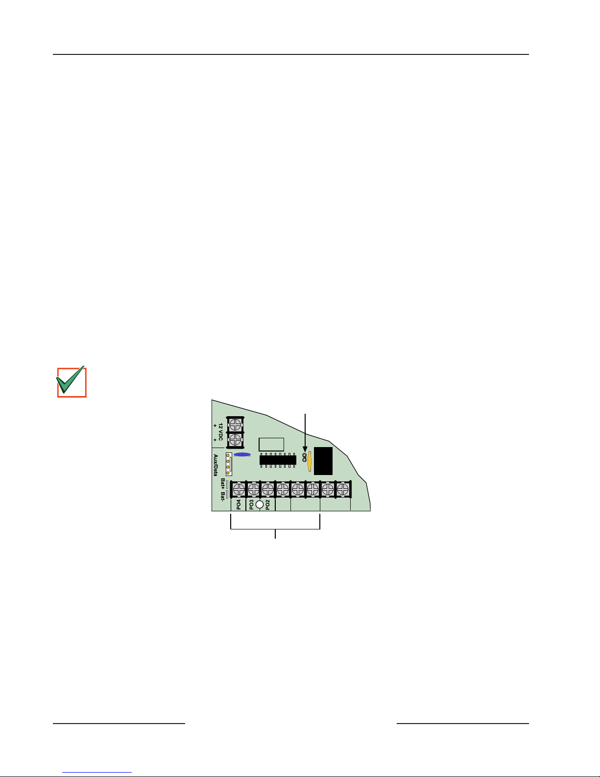
D6412/D4412
I
T
Power Outputs
5.5 Output Programming
Programmable Output 2 (PO2) can be configured as a supervised siren driver. See Global Output Configuration in the D6412/
D4412 Program Entry Guide (P/N: 45351) for programming instructions. When programmed as a siren driver, PO2 draws
power from the Alrm + terminal. W hen c onnected to a 4 Ω horn/speaker , PO2 draws 380 mA of power . W hen connected to
an 8 Ω horn/speaker, it draws 330 mA of power. Use the appropriate current draw in y our total alarm power calculation.
• Programmable Output 1 (PO1): PO1 terminals can be configured as an alarm power output. JP2-PO1 Jumper
must be closed. The default configuration for Programmable Output 1 makes it a dry contact, normally open
relay . The PO1 J umper is open. See Figure 5 for jumper location.
• Programmable Output 2 (PO2): Output PO2 can be used with Alarm+ as a supervised siren driver. Connect an
approved 4 or 8 Ω siren. Alte rnatively, PO2 can sink up to 500 mA 12 VDC. F or larger loads, use a Bosch Security
Systems D133 Relay Module or Bosch Security Systems D134 Dual Relay Module.
• Programmable Outputs 3 and 4 (PO3 and PO4): Outputs PO3 and PO4 can be configured for Alarm Output.
These outputs can sink up to 500 mA 12 VDC each. For larger loads, use a Bosch Security Systems D133 Relay
Module or Bosch Security Systems D134 Dual Relay Module.
Powe r restricted for fire and com bined fire/burglary systems: Use the Fir e S ys te m Power Formula in Section 5.4.1 Available
Power to calculate the current available for fire and combined fire/burglary systems.
Unexpected Output at PO1 to PO4: If these outputs do not provide the alarm output you expect:
• Check the programming for Programmable Outputs in the Outputs section of the D6412/D4412 Program Entry
Guide (P/N: 45351).
• Check the Point Index Co nfiguration section of the D6412/D4412 Program Entry Guide to verify the points you
are activating are programmed for alarm output.
MPORTAN
If Programmable Output 2 is configured as a supervised siren driver (in combination with the Alrm + terminal),
ΩΩ
ΩΩ
Ω
or 8
Ω
you must connect a 4
ΩΩ
siren/speaker to PO2 to clear the siren/speaker supervision trouble.
ΩΩ
PO 1 Jumper
JP2-PO1
R
Y
G
B
Select
Alrm
+
PO1
AB
-
+
L-1
Programmable Outputs 1-4
Figure 5: On-Board Outputs
D6412/D4412 Operation and Installation Guide
Page 22 © 2003 Bosch Security Systems45349E
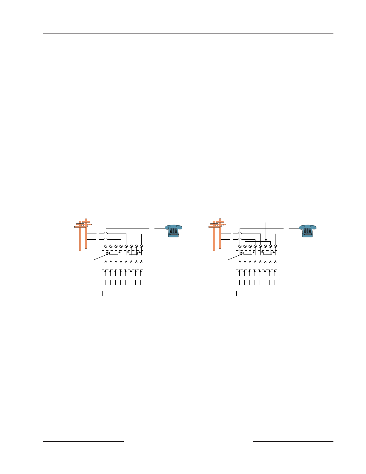
D6412/D4412
Telephone Connections
6.0 Telephone Connections
6.1 Registration
The Bosch Security Systems D6412/D4412 Control Panel is registered with the Federal Communication Commission (FCC)
under Part 68 for connection to the public telephone system using an RJ31X or RJ38X jack installed by your local phone
company .
6.2 Notification
Do not connect registered equipment to party lines or coin-operated telephones. You must notify the local telephone
company and supply them with the following information before connecting the panel to the telephone network.
• Line to which you are connecting the panel
• Make (Bosch Security Systems), model (D6412 or D4412), and serial number of the panel
• FCC registration number: ESVMUL-46531-AL-E
• Ringer equivalence for the panel: 0.1 B
6.3 Location
T o prevent jamming of signals, wire the RJ31X jack or RJ38X jack to support line seizure as shown in Figure 6. Install the jack
on the street side of the phone switch, wired ahead of any PBX equipment. Line seizure temporarily interrupts normal phone
usage while the communicator transmits data. After installation, confirm that the panel seizes the line, acquires dial tone,
reports correctly to the receiver , and releases the phone line to the in-house phone system .
Outside Telco
(PSTN)
T
R
R1
T1
Premises
Telephone
Outside Telco
(PSTN)
Strap
T
R
R1
T1
Premises
Telephone
Bar Short r em ov e d on
T elco Conn ector B lock
insertion - positions
1&4 and 5&8.
1 2 3 6 7 8
4 5
1 2 3 4 5 6 7 8
R1 T1R T
To Control Panel
RJ31X Jack Connections
RJ31X Jack
Telco Connector Block
Bar Short removed on
T elco Conn ector Bloc k
insertion - positions
1&4 and 5&8.
1 2 3 6 7 8
4 5
1 2 3 4 5 6 7 8
R1 T1R T
To C ontrol Panel
RJ38X Jack Connections
RJ38X Jack
Telco Connector Block
Figure 6: RJ31X/RJ38X Wiring
6.4 Phone Cord Connection
Connect the flying leads of a D164 T elephone Cord to the telephone te rminals labeled R, R1, T1, and T. The terminals are
located on the right side of the panel. Connect the other end of the cord to the RJ31X jack or RJ38X jack.
6.5 System Status LED (Red)
The System Status LED shows system status, including phone status as described in Table 4. Figure 4 shows the location of
the LED on the panel.
6.6 Dialing Format
You can program the system to use DTMF or pulse dialing. See DTMF/Pulse Dialing in the D6412/D4412 Program Entry
Guide (P/N: 45351).
D6412/D4412 Operation and Installation Guide
Page 23© 2003 Bosch Security Systems 45349E
 Loading...