

Bosch D132B Installation Manual

Multi-use Reversing Relay Module
D132B
en Installation Instructions


Multi-use Reversing Relay Module Table of Contents | en 3
Table of contents
1
2
3
4
4.1 Wiring to a D7022 FACP 7
4.2 Wiring to a D7024 or an FPD-7024 FACP 10
4.2.1 Two-wire configurations 10
4.2.2 Four‑wire configurations 12
4.2.3 Configurations using filtered power 15
4.3 Wiring to a D8024, D9024, or D10024 FACP 18
5
Notices 4
Device Description 5
Installing the module 6
Wiring the module 7
Specifications 21
Bosch Security Systems, Inc. Installation Instructions 2012.12 | 1.0 | F.01U.279.509
!
i
4 en | Notices Multi-use Reversing Relay Module
1
Notices
These instructions cover the installation of the D132B Multi-Use Reversing Relay Module in a
fire system supervised by a fire alarm control panel (FACP).
Install, test and maintain the D132B according to these instructions, NFPA 72, local codes,
and the authority having jurisdiction (AHJ). Failure to follow these instructions can result in
failure of the detector to initiate an alarm event. Bosch Security Systems, Inc. is not
responsible for improperly installed, tested or maintained devices.
Warning!
Follow these instructions to avoid personal injury and damage to equipment.
Notice!
NFPA 72 requires a complete system‑wide functional test be performed following any modifi-
cations, repair, upgrades or adjustments made to the system’s components, hardware, wir-
ing, programming and software/firmware.
2012.12 | 1.0 | F.01U.279.509 Installation Instructions Bosch Security Systems, Inc.

Multi-use Reversing Relay Module Device Description | en 5
2
Device Description
The D132B is a multipurpose, fully configurable, smoke power-reversing module for activating
detectors with local annunciation. The module will operate both two-wire and four-wire 24 V
circuits, and also works with Class A or Class B initiating circuits.
An alarm latch connection is provided to allow an initiating loop to be held in alarm after the
detector loop power has been reversed to activate any sounders.
The module does not affect compatibility between the FACP and detectors, or the FACP and
notification appliance circuits (NACs).
The maximum current available from the FACP smoke power terminals or NACs limits the total
number of reversible smoke detectors that can be connected to the module.
Consult the FACP’s installation instructions for compatibility with the D132B Multi-Use
Reversing Relay Module.
Bosch Security Systems, Inc. Installation Instructions 2012.12 | 1.0 | F.01U.279.509

!
i
6 en | Installing the module Multi-use Reversing Relay Module
3
Installing the module
The supplied screw and Snap Trac are required to mount the module. It can be mounted
anywhere within the FACP’s enclosure using the supplied screw with double sided tape as a
mounting aid. Several methods of wiring the module can be used.
Caution!
The voltage supplied to the NAC sounder power terminals must be compatible with the detec-
tor voltage requirements when in alarm (reverse polarity). Unfiltered NAC output power is
typically not compatible with detector sounder power requirements. Use a source of filtered
power (for example, smoke power) for NAC sounder power on panels with unfiltered NAC
output power, and ensure that the total current draw for detector sounders does not exceed
the panel’s rated filtered power output capacity.
Notice!
The D7022, D7024, D8024, D9024, and D10024 do not meet the requirements of UL864, 9th
edition. For UL applications, use the FPD‑7024.
2012.12 | 1.0 | F.01U.279.509 Installation Instructions Bosch Security Systems, Inc.

!
!
i
Multi-use Reversing Relay Module Wiring the module | en 7
4
4.1
Wiring the module
Warning!
Maintain a ¼ in. (6.35 mm) minimum distance between power limited and non‑power limited
wiring.
Warning!
Since full or auxiliary power is applied to loop output terminals TB 1 and TB 2 during an
alarm, only connect reversing smoke detectors to these terminals. Do not connect pull sta-
tions, heat detectors or other such devices. Doing so will damage the D132B module and/or
the FACP.
Wiring to a D7022 FACP
Notice!
The D132B module must be mounted within the control panel enclosure for this application
and the D7022 must be set for 24 V operation.
Bosch Security Systems, Inc. Installation Instructions 2012.12 | 1.0 | F.01U.279.509
8 en | Wiring the module Multi-use Reversing Relay Module
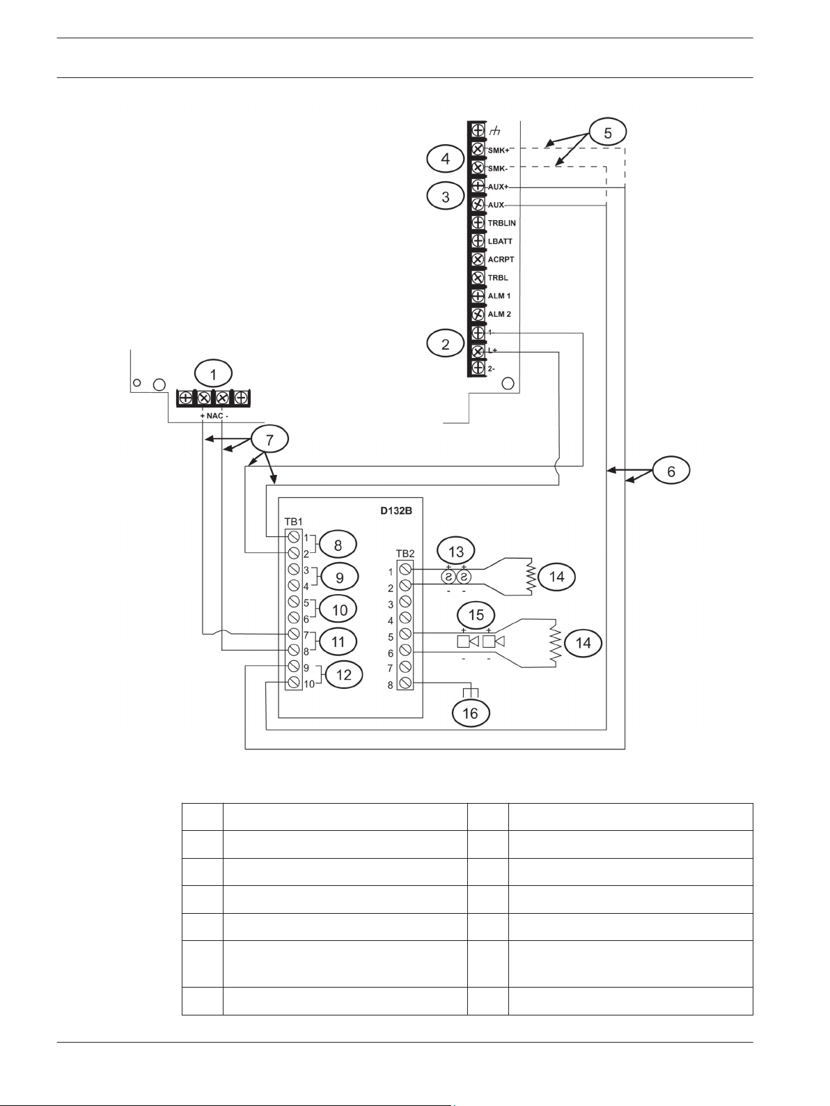
Figure 4.1: Wiring a D132B (2‑wire, Class B) to a D7022 FACP
1 NAC output 9 Class A
2 Input point 10 Latch
3 Auxiliary power 11 NAC
4 Smoke power 12 24 VDC
5 Optional filtered power connections 13 24 V 2‑wire reversing detectors
6 Unfiltered power; power limited but
not supervised
14 2.2 kΩ EOL (power limited and
supervised); P?N: F.01U.034.504
7 Power limited and supervised 15 24 V NACs
2012.12 | 1.0 | F.01U.279.509 Installation Instructions Bosch Security Systems, Inc.
 Loading...