

Bosch BVA 2.0 Installation Instructions Manual
Bosch BVA 2.0 Series Air Handler
2-3-4-5 Ton Capacity
R410A
Installation Instructions

|
2
Bosch IDS BVA 2.0 Installation Instructions
Data subject to change
02.2019 | Bosch Thermotechnology Corp.

Installation Instructions Bosch IDS BVA 2.0 | 3
Table of Contents
1 Key to Symbols and Safety Instructions 4
1.1 Key to Symbols 4
1.2 Safety 4
2 General 6
2.1 Installations in High Humidity Environments 6
2.2 Unit Dimensions 9
3 Applications 10
3.1 Vertical Upfl ow 10
3.2 Vertical Downfl ow 10
3.3 Horizontal 10
3.4 Installation in an Unconditioned Space 12
4 Electrical wiring 13
4.1 Power Wiring 13
4.2 Control Wiring 13
4.3 Grounding 13
4.4 Electrical Data 13
4.5 Electric Heat Kit MCA/MOP Data 14
5 Airfl ow Performance 15
5.1 Indoor Fan Motor Function 16
6 Ductwork 17
7 Refrigerant Connections 18
7.1 Condensate Drain Connection 18
8 Air Filter (Not Factory-Installed) 19
9 Filter Installation Dimensions 20
10 Maintenance 21
10.1 Cleaning Precautions 21
10.2 Regular Maintenance 21
11 Wiring Diagrams 22
Bosch Thermotechnology Corp. | 02.2019
Data subject to change
|
4
Bosch IDS BVA 2.0 Installation Instructions
1 Key to Symbols and Safety Instructions
1.1 Key to Symbols
Warnings
Warnings in this document are identifi ed by a warning triangle
printed against a grey background.
Keywords at the start of a warning indicate the type and seriousness
of the ensuing risk if measures to prevent the risk are not taken.
The following keywords are defi ned and can be used in this document:
DANGER indicates a hazardous situation which, if not avoided, will result
in death or serious injury.
WARNING indicates a hazardous situation which, if not avoided, could
result in death or serious injury.
CAUTION indicates a hazardous situation which, if not avoided, could
result in minor to moderate injury.
NOTICE is used to address practices not related to personal injury.
Important information
1.2 Safety
Please read before proceeding
WARNING:
These instructions are intended as an aid to qualified,
licensed service personnel for proper installation,
adjustment and operation of this unit. Read these
instructions thoroughly before attempting installation or
operation. Failure to follow these instruction may lead to
improper installation, adjustment, service or maintenance
possibly resulting in fire, electrical shock, property damage,
personal injury or death.
This document is customer property and is to remain with this unit.
These instructions do not cover all the diff erent variations of systems nor
does it provide for every possible contingency to be met in connection
with installation.
WARNING: FIRE, ELECTRICAL SHOCK, PROPERTY DAMAGE,
PERSONAL INJURY, OR DEATH
All phases of this installation must comply with NATIONAL,
STATE AND LOCAL CODES. If additional information is
required please contact your local distributor.
This symbol indicates important information where there is no risk to
people or property.
WARNING: ELECTRICAL SHOCK
Disconnect all power to unit before installing or servicing.
More than one disconnect switch may be required to
deenergize the equipment. Hazardous voltage can cause
severe personal injury or death.
WARNING: ELECTRICAL SHOCK
If removal of the blower assembly is required, all disconnect
switches supplying power to the equipment must be
deenergized and locked (if not in sight of unit) so the
field power wires can be safely removed from the blower
assembly. Failure to do so can cause electrical shock
resulting in personal injury or death.
WARNING: FIRE, ELECTRICAL SHOCK, PROPERTY DAMAGE,
PERSONAL INJURY, OR DEATH
Because of possible damage to equipment or personal
injury, installation, service, and maintenance should
be performed by trained, qualified service personnel.
Consumer service is recommended only for filter cleaning /
replacement. Never operate the unit with the access panels
removed.
Data subject to change
02.2019 | Bosch Thermotechnology Corp.
Installation Instructions Bosch IDS BVA 2.0 | 5
WARNING:
This product can expose you to chemicals including Lead
and Lead components, which are known to the State
of California to cause cancer and birth defects or other
reproductive harm. For more information go to
P65Warnings.ca.gov
WARNING: ELECTRICAL SHOCK
The unit must be permanently grounded. Failure to do so can
result in electrical shock causing personal injury or death.
CAUTION: FIRE HAZARD
The material of plenum and ductwork must meet the latest
edition of the NFPA 90B standard.
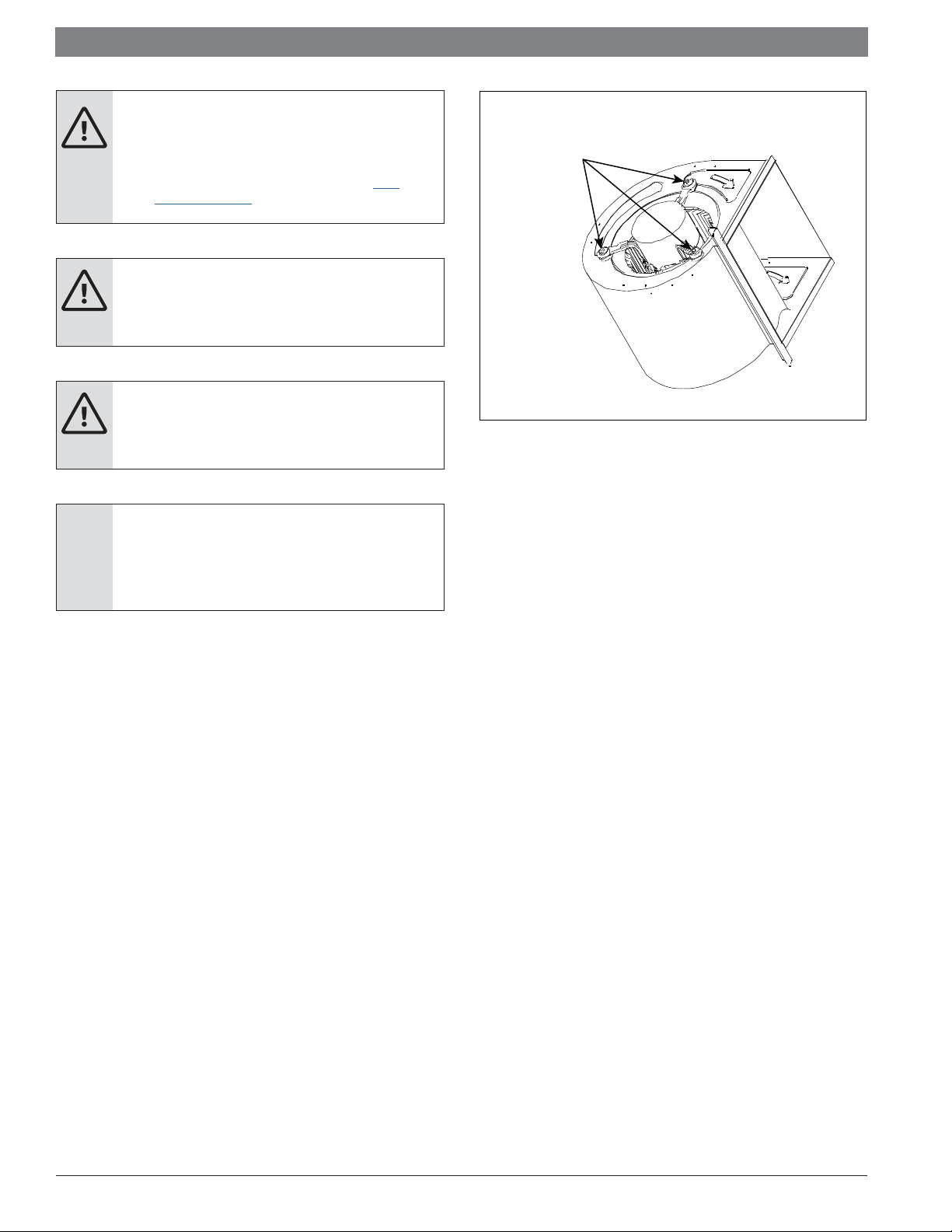
NOTICE:
Make sure the blower motor support is tight (3-motor
mounting bolts - Fig. 1). Then check if wheel is tightly
secured to motor shaft before operating unit.
.
www.
Blower Motor
Mounting Bolt
Figure 1
Bosch Thermotechnology Corp. | 02.2019
Data subject to change
|
6
Bosch IDS BVA 2.0 Installation Instructions
2 General
The unit can be positioned for bottom air return in the upfl ow position, left and right
air return in the horizontal position and top air return in downfl ow position.
This air handler provides the fl exibility for installation in any upfl ow, downfl ow or
horizontal application. Adjust the motor speed tap through the DIP switch (located
on the Air Handler's control board) to select correct air fl ow according to airfl ow
performance table in Section 5. Please refer to wiring diagram for Dip Switch
settings.
Please refer to Figure 8 for high and low voltage wiring connections.
To ensure the proper installation, select a solid and level site. Ensure enough
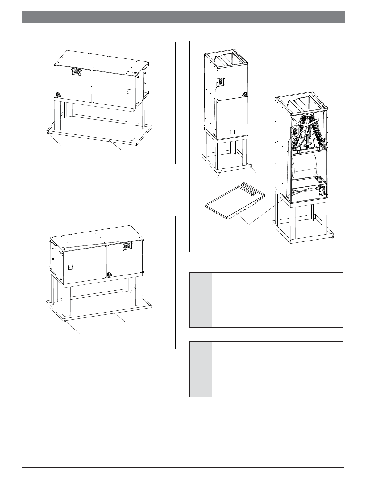
2.1 Installations in High Humidity Environments
When the unit is installed in a hot and humid place, if the humidity inside the
installation space exceeds 86℉ and RH 80%, it is recommended to insulate the
cabinet exterior. Use glass wool or polyethylene foam as insulation; the thickness
should be more than 2 in. and it must fi t inside the installation space opening.
Condensation may come from the surface of the insulation. Be sure to use
insulation that is designed for use with HVAC Systems. Condensation may be
produced on surface during cooling operation. It is also recommended to use
auxiliary drain pan and secure the unit fi rmly to prevent it from falling. See Figures
3, 4, 5, & 6.
Refer to local code requirements for usage of auxiliary drain pans.
clearance is maintained for installation and maintenance.
AIRFLOW
≥ "04≥40"
Clearances in the Horizontal Position
!
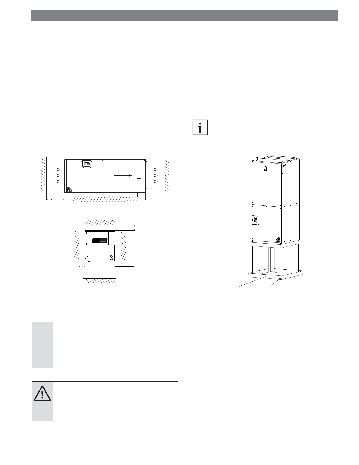
Clearances in the Vertical Position
Figure 2 Required Clearances
NOTICE:
The installed unit must have the required clearances as
shown in Figure 2. Failure to follow these instructions may
result in equipment damage and/or premature equipment
failure.
WARNING: FIRE HAZARD
Keep flammable material and vapors, such as gasoline, away
from the air handler. Failure to follow these instructions can
result in death, explosion, or fire.
Front of unit
ı
25’’
!
!
Auxiliary drain pan
Figure 3
Installed Vertical Upfl ow
Drain piping
Data subject to change
02.2019 | Bosch Thermotechnology Corp.
Installation Instructions Bosch IDS BVA 2.0 | 7
Drain piping
Figure 4 Installed Horizontal Right
Drain piping
Auxiliary drain pan
Auxiliary drain pan
Auxiliary drain pan
Inner extra drain pan
Figure 6
Installed Vertical Downfl ow
NOTICE:
Inner extra drain pan is recommended to be installed for 4
Drain piping
and 5 ton vertical downflow applications installed in high
humidity environments. This inner extra drain pan can be
ordered from the manufacturer as a spare part. Refer to
Figure 6.
Figure 5
Installed Horizontal Left
Bosch Thermotechnology Corp. | 02.2019
NOTICE:
For high humidity installations which include electric
heat strips, it is recommended to install spacing brackets
(available as a spare part from the manufacturer) between
the heater and the heater collar to prevent condensation
from forming on the collar.
Data subject to change
|
8
Bosch IDS BVA 2.0 Installation Instructions
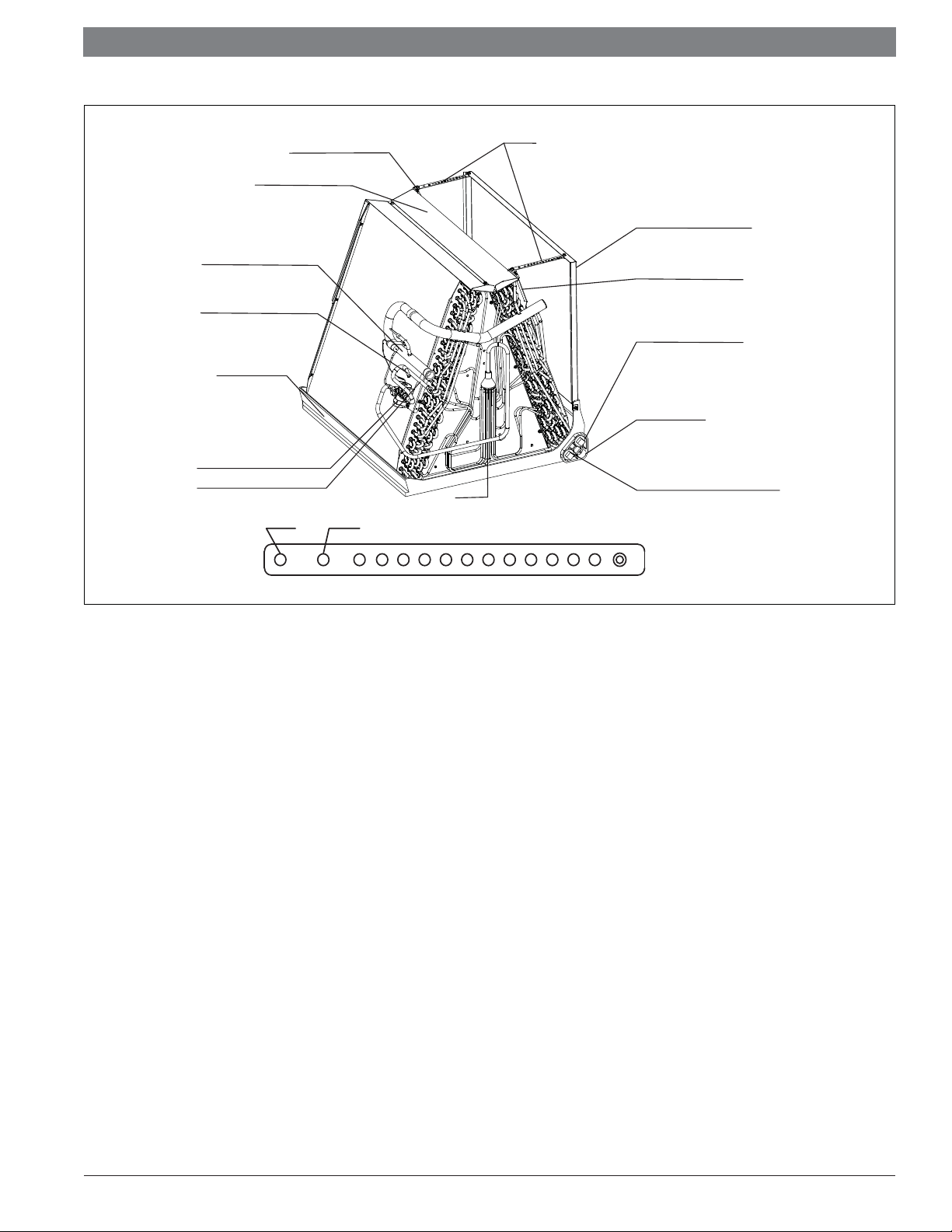
REAR WATER CATCHER
TOP AIR STOP
VAPOR LINE CONNECTION
SENSOR T2 LOCATION
VERTICAL DRAIN PAN
NON-ADJUSTABLE TXV
LIQUID LINE CONNECTION
THIS SYSTEM IS CHARGED WITH NITROGEN BEFORE SHIPMENT
60/48K 36/24K
STRAPS
STRAPS
HORIZONTAL DRAIN KIT
FRONT WATER CATCHER
AUXILIARY HORIZONTAL
DRAIN CONNECTION
PRIMARY DRAIN
CONNECTION
AUXILIARY UPFLOW/DOWNFLOW
DRAIN CONNECTION
Figure 7
Indoor Coil and Drain Pan Set-Up
Data subject to change
02.2019 | Bosch Thermotechnology Corp.
Installation Instructions Bosch IDS BVA 2.0 | 9
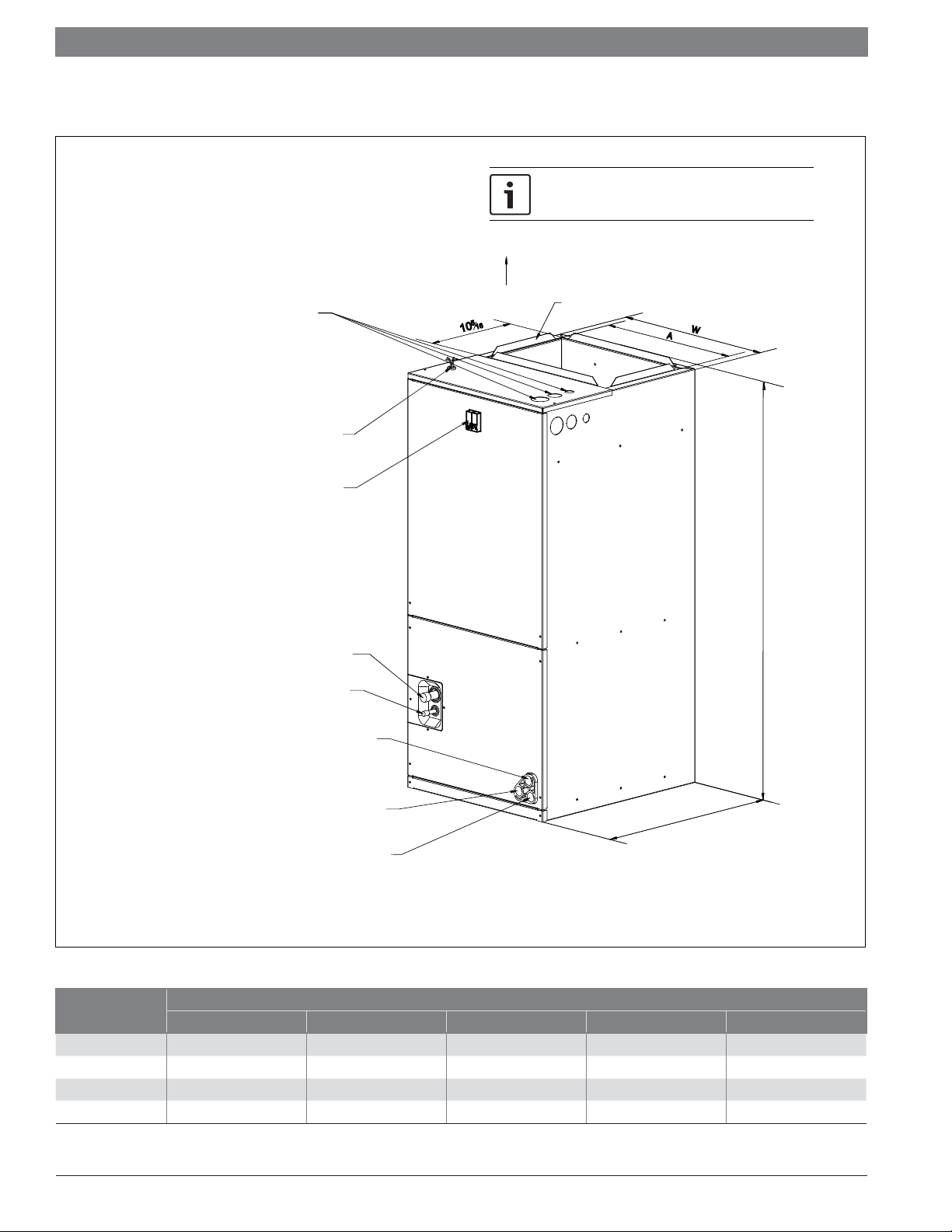
2.2 Unit Dimensions
25” CLEARANCE IS REQUIRED IN THE FRONT OF
THE UNIT FOR FILTER AND COIL MAINTENANCE.
ELECTRICAL CONNECTIONS
THROUGH TOP OR EITHER SIDE
SUPPLY AIR
HIGH VOLTAGE CONNECTION 1-
7
3
/
1-
/
8
"
8
",
DIA. KNOCK OUTS
LOW VOLTAGE CON
CIRCUIT BREAK
NECTION
ER SWITCH
(FOR ELECTRIC HEATER ONLY)
VA
POR LINE CONNECTION COPPER TUBE (SWEAT)
LIQUID LINE CON
NECTION COPPER TUBE (SWEAT)
AUXILIARY DRAIN CONNECTION 3/4"
FEMALE PIPE THREAD (NPT)
3
/
4
",
FLANGES ARE PROVIDED
FOR FIELD INSTALLATION
5
6
1
0
1
W
A
H
AUXILIARY DRAIN CONNECTION 3/4"
FEMALE PIPE THREAD (NPT)
PRIMARY D
FEMALE PIPE THREAD (NPT)
Figure 8
Model Size
Unit Height "H" Unit Width "W" Unit Length "D" Supply Duct "A" Liquid Line / Vapor Line
24 46-1/2 [1180] 19-5/8 [500] 21-5/8 [550] 18 [456] 3/8 / 3/4 [9.5]/[19]
36 46-1/2 [1180] 19-5/8 [500] 21-5/8 [550] 18 [456] 3/8 / 3/4 [9.5]/[19]
48 54-1/2 [1385] 22 [560] 24 [610] 19-1/2 [496] 3/8 / 7/8 [9.5]/[22]
60 54-1/2 [1385] 22 [560] 24 [610] 19-1/2 [496] 3/8 / 7/8 [9.5]/[22]
Table 1
Bosch Thermotechnology Corp. | 02.2019
D
RAIN CONNECTION 3/4"
UPFLOW UNIT SHOWN:
THE UNIT CAN BE POSITIONED FOR BOTTOM AIR RETURN IN THE UPFLOW POSITION, LEFT AND
RIGHT AIR RETURN IN THE HORIZONTAL POSITION, OR TOP AIR RETURN IN DOWNFLOW POSITION.
Dimensions Inch [mm]
Data subject to change
 Loading...