

Bosch AQ 125BO NG, AquaStar 125BO LP, AquaStar 125BO NG Use And Care Manual
BOSCH
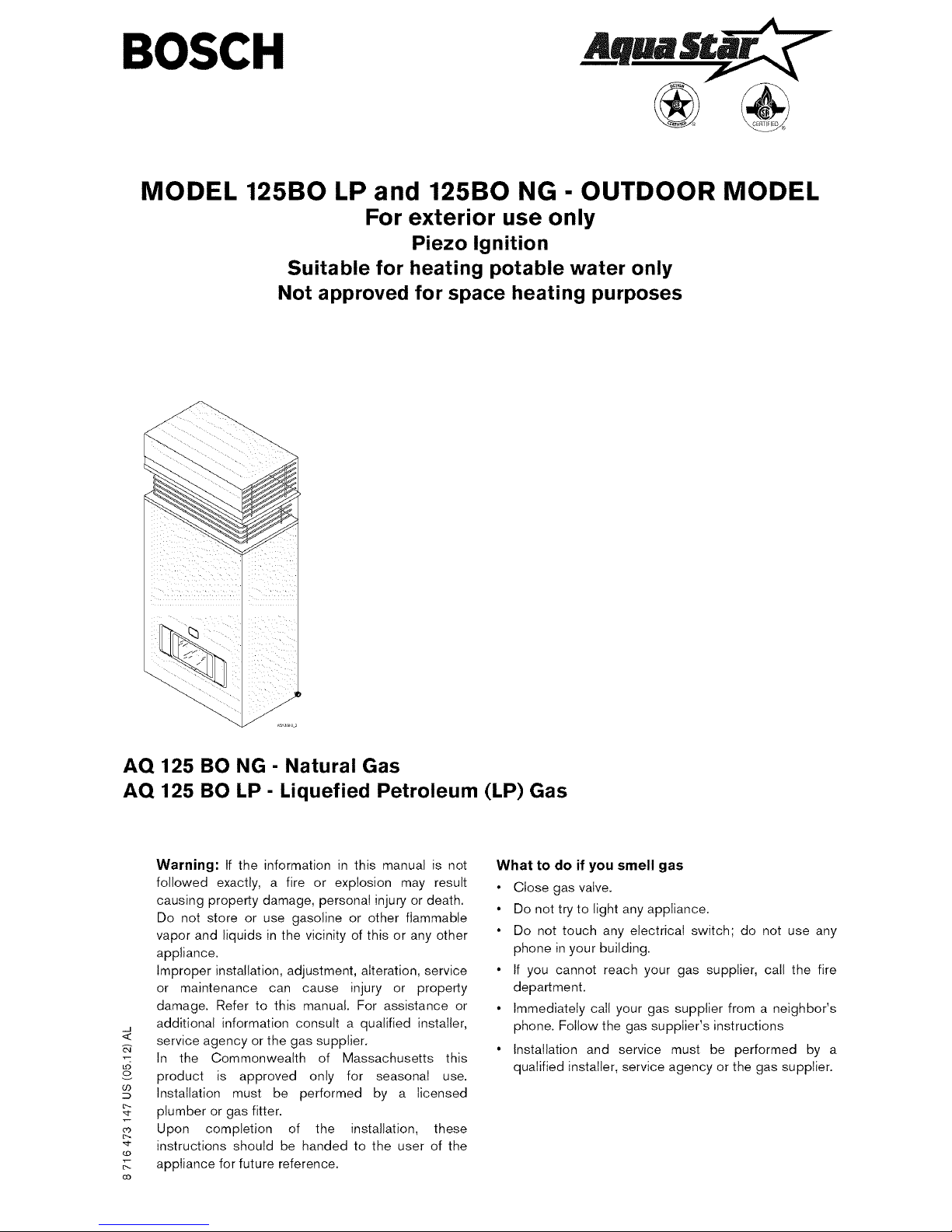
MODEL 125BO LP and 125BO NG - OUTDOOR MODEL
For exterior use only
Piezo Ignition
Suitable for heating potable water only
Not approved for space heating purposes
AQ 125 BO NG - Natural Gas
AQ 125 BO LP - Liquefied Petroleum (LP) Gas
-J
LO
o
CO
_O
oo
Warning: If the information in this manual is not
followed exactly, a fire or explosion may result
causing property damage, personal injury or death.
Do not store or use gasoline or other flammable
vapor and liquids in the vicinity of this or any other
appliance.
Improper installation, adjustment, alteration, service
or maintenance can cause injury or property
damage. Refer to this manual. For assistance or
additional information consult a qualified installer,
service agency or the gas supplier.
In the Commonwealth of Massachusetts this
product is approved only for seasonal use.
Installation must be performed by a licensed
plumber or gas fitter.
Upon completion of the installation, these
instructions should be handed to the user of the
appliance for future reference.
What to do if you smell gas
• Close gas valve.
• Do not try to light any appliance.
• Do not touch any electrical switch; do not use any
phone in your building.
• If you cannot reach your gas supplier, calI the fire
department.
• Immediately calI your gas supplier from a neighbor's
phone. Follow the gas supplier's instructions
• Installation and service must be performed by a
qualified installer, service agency or the gas supplier.
Index
Index
1 Warning 2
Warning
2 Appliance details 4
2.1 Features 4
2.2 AQ125 BO specifications (Technical data) 4
2.3 Unpacking the AQ-1 25-BO heater 5
2.4 General rules to follow for safe operation 5
2.5 Dimensions and installation clearances 6
3 Installation instructions 7
3.1 Introduction 7
3.2 Proper location for installing your heater 7
3.3 Heater placement and clearances 8
3.4 Mounting installation 8
3.5 Gas piping & connections 10
3.6 Measuring gas pressure 12
3.7 Water connections 12
3.8 Electrical connections 13
4 Operation instructions 14
4.1 For your safety read before operating your water
heater 14
4.2 Lighting instructions 14
4.3 To turn off appliance 14
4.4 Setting the water temperature 14
5 Maintenance and service 16
5.1 Maintenance intervals 16
5.2 Water valve 16
5.3 Pilot 16
5.4 Main burners 16
5.5 Vent assembly 16
5.6 Mineral scale build-up 16
Featuring
Piezo Ignition
For your safety
Do not store or use gasoline or other flammable,
combustible or corrosive vapors and liquids in the
vicinity of this or any other appliance,
6 Troubleshooting 17
6.1 Introduction 1 7
6.2 Pilot will not light 1 7
6.3 Pilot will light but not stay on when button released 1 7
6.4 Burner do not ignite with water flow 1 7
6.5 Hot water temp fluctuates from hot to cold 1 7
6.6 Water is too hot 18
6.7 Water is not hot enough 18
7 Interior components and diagram parts list 19
7.1 Interior components 19
7.2 Components diagram 20
7.3 Parts list 21
8 Protecting the environment 22
9 Twelve Year Limited Warranty 23
2 8 716 473 147
Warning
What to do if you smell gas
• Close gas valve.
• Do not try to light any appliance.
• Do not touch any electrical switch; do not use any
phone in your building.
• Immediately call your gas supplier from a neighbor's
phone. Follow the gas supplier's instructions.
• If you cannot reach your gas supplier, call the fire
department.
• Installation and service must be performed by a
qualified installer, service agency or the gas supplier.
_k
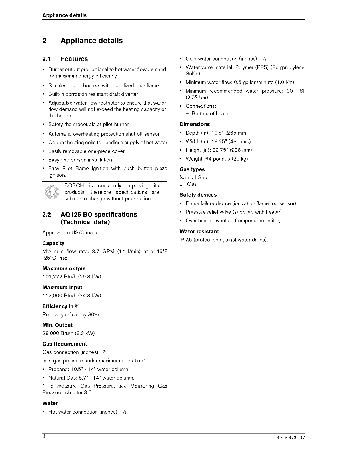
LL_ Vapors from flammable
liquids will explode and
catch fire causing death
or severe bums.
Do not use or store flammable
=roducts such as gasoline,
solvents or adhesives in the
same room or area near the
water heater.
Keep flammable products:
1. far away from heater,
2. in approved containers,
3. tightly closed and
4. out of children's reach.
Water heater has a main
burner:
1. which may come on
any time and
2. will ignite flammable vapors.
Vapors:
1, cannot be seen_
2, are heavier than air,
3, go a long way on the floor and
4, can be carried from other
rooms to the pilot flame by
air currents.
Installation: area at least 18" above the
Do not install water heater floor. This will reduce, but not
where flammable products will eliminate, the risk of vapors
be stored or used unless the being ignited by the main
main burner and pilot flames burner or pilot flame.
Read and follow water heater warnings and instructions.
If owners manuals is missing, contact the retailer or manufacturer.
2
o
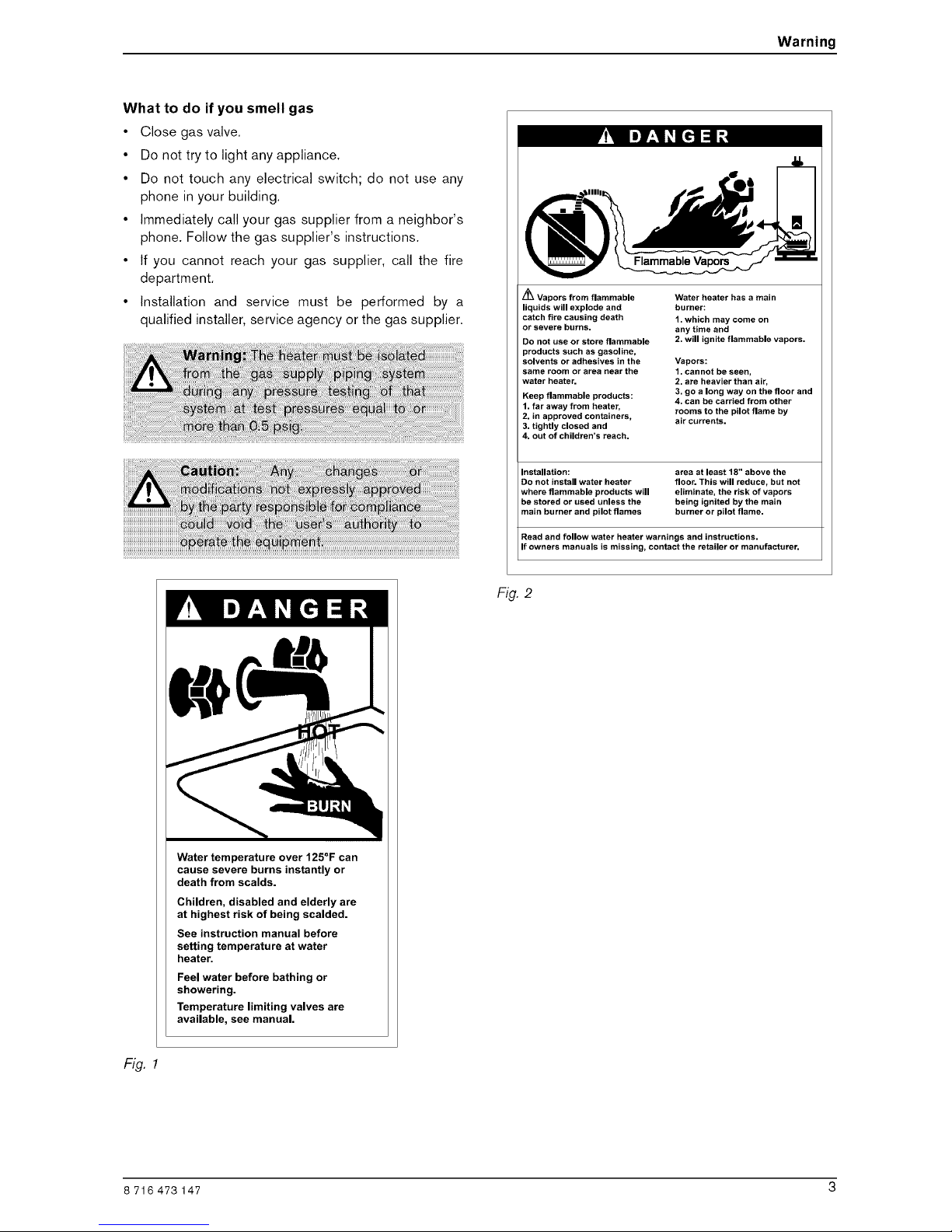
Water temperature over 125 F can
cause severe burns instantly or
death from scalds.
Children, disabled and elderly are
at highest risk of being scalded.
See instruction manual before
setting temperature at water
heater.
Feel water before bathing or
showering.
Temperature limiting valves are
available, see manual.
Fig.
Fig. 1
8 716 473 147 3
Appliance details
2 Appliance details
2,1 Features
Burner output proportional to hot water flow demand
for maximum energy efficiency
Stainless steel burners with stabilized blue flame
Built-in corrosion resistant draft diverter
Adjustable water flow restrictor to ensure that water
flow demand will not exceed the heating capacity of
the heater
• Safety thermocouple at pilot burner
• Automatic overheating protection shut-off sensor
• Copper heating coils for endless supply of hot water
• Easily removable one-piece cover
• Easy one person installation
• Easy Pilot Flame Ignition with push button piezo
ignition.
BOSCH is constantly improving its
products, therefore specifications are
subject to change without prior notice.
2,2 AQ125 BO specifications
(Technical data)
Approved in US/Canada
Capacity
Maximum flow rate: 3.7 GPM (14 I/min) at a 45°F
(25°C) rise.
Maximum output
101,772 Btu/h (29.8 kW)
Maximum input
117,000 Btu/h (34.3 kW)
Efficiency in %
Recovery efficiency 80%
Min. Output
28,000 Btu/h (8.2 kW)
Gas Requirement
Gas connection (inches) - 3/4"
Inlet gas pressure under maximum operation*
• Propane: 10.5" - 14" water column
• Natural Gas: 5.7" - 14" water column.
* To measure Gas Pressure, see Measuring Gas
Pressure, chapter 3.6.
Water
• Hot water connection (inches) - 1/2"
• Cold water connection (inches) - 1/2"
• Water valve material: Polymer (PPS) (Polypropylene
Sulfid)
• Minimum water flow: 0.5 gallon/minute (1.9 I/m)
• Minimum recommended water pressure: 30 PSI
(2.07 bar)
• Connections:
- Bottom of heater
Dimensions
• Depth (in): 10.5" (265 mm)
• Width (in): 18.25" (460 mm)
• Height (in): 36.75" (936 mm)
• Weight: 64 pounds (29 kg).
Gas types
Natural Gas.
LP Gas
Safety devices
• Flame failure device (ionization flame rod sensor)
• Pressure relief valve (supplied with heater)
• Over heat prevention (temperature limiter).
Water resistant
IP X5 (protection against water drops).
4 8 716 473 147
Appliance details
2.3 Unpacking the AQ-125-BO heater
This heater is packed securely.
Before installing the unit, be certain you have the
correct heater for your type of Gas - Propane or
Natural Gas. Identification labels are found on the
shipping box, and on the rating plate which is located on
the right side panel of the cover.
The box includes:
• Pressure relief valve
• Heat shield
• Mounting screws
• Product registration card
• Installation manual.
Do not lose this manual, there is a charge for a
replacement,
Please complete and return the enclosed product
registration card.
The AQ125 BO is not approved or designed for:
• Manufactured (mobile) homes, RV's or boats
• Heating or other recirculating/pumping applications*
• Solar/preheat backup or high temperature booster
use
* This includes domestic hot water circulator pump loop
systems that may previously exist in a home hot water
system. The use of a small electric mini-tank (4-6 gallon
size) should be used for this application; when
designed so the pump will circulate the hot water in the
mini-tank only and through the building's hot water
return loop (timed or thermostatic controlled operation
of the pump iscommonly done). The AQ125 BO should
be plumbed in line before the mini-tank water heater,
contact BBTNA if further instruction is needed.
2.4 General rules to follow for safe
operation
• 1. You should follow these instructions when you
install your heater. In the United States: The
installation must conform with local codes or, in the
absence of local codes, the National Fuel Gas Code
ANSI Z223.1/NFPA 54.
In Canada: The Installation should conform with
CGA B149.(1,2) INSTALLATION CODES and /or
local installation codes.
• 2. Carefully plan where you install the heater. Proper
clearances must be followed.
• 3. The appliance must be isolated from the gas
supply piping system by closing its individual manual
gas shutoff valve (not supplied with heater) during
any pressure testing at pressures in excess of 1/2Psig
(3.5 kPa).
The appliance and its gas connection must be leak
tested before placing the appliance in operation.
• 4. Keep water heater area clear and free from
combustibles and flammable liquids. Do not locate
the heater over any material which might burn.
• 5. Correct gas pressure is critical for the optimum
operation of this heater. Gas piping must be sized to
provide the required pressure at the maximum output
of the heater, while all the other gas appliances are in
operation. Check with your local gas supplier, and
see the section on connecting the gas supply.
• 6. Should overheating occur or the gas supply fail to
shut off, turn off the gas supply at the manual gas
shut off valve, on the gas line. Note: manual gas
shutoff valve is not supplied with the heater.
• 7. Do not use this appliance if any part has been
underwater. Immediately call a qualified service
technician to inspect the appliance and to replace
any part of the control system and any gas control
which has been underwater.
8 716 473 147 5
Appliance details
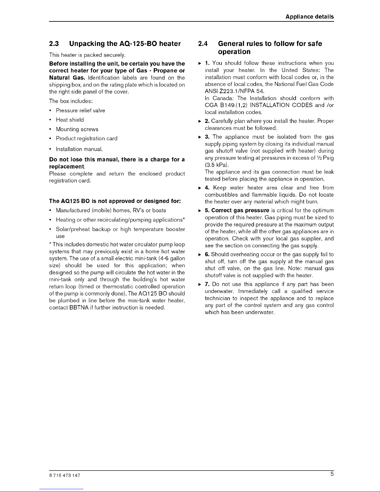
2,5 Dimensions and installation clearances
10_½ "
18"
_0
03
Fig. 3 Dimensions
WATER INLET
WATER OUTLET
GAS INLET
AQ125B 10.JS
B
Fig, 4 Minimum clearances
3ft.
4 ft.
0"
4 ft.
1 ft.
Table 1 Minimum clearances
6 8 716 473 147
Installation instructions
3 Installation instructions
3.1 Introduction
Please follow these instructions. Failure to follow
instructions may result in:
• Damage or injury.
• Improper operation.
• Loss of warranty.
Please contact BBT North America with any questions.
3,2 Proper location for installing your
heater
Carefully select the location of the water heater.
Follow the guidelines below:
• 1, Locate the heater where an adequate gas line size
and plumbing connections are feasible and
convenient,
• 2, The hot water lines should be kept short to save
energy. Centrally locating the water heater is best. It
is always best to have hot water lines insulated to
prevent the possibility of any freeze damage.
• 3. The water in this heater is cold and always remains
cold except for the times that hot water is being used.
The heater is equipped with freeze prevention
equipment that will operate and prevent freezing of
the water in the heater to 5°F with no wind chill,
Electrical power must be maintained to the heater to
allow this to function,
8 716 473 147 7
Installation instructions
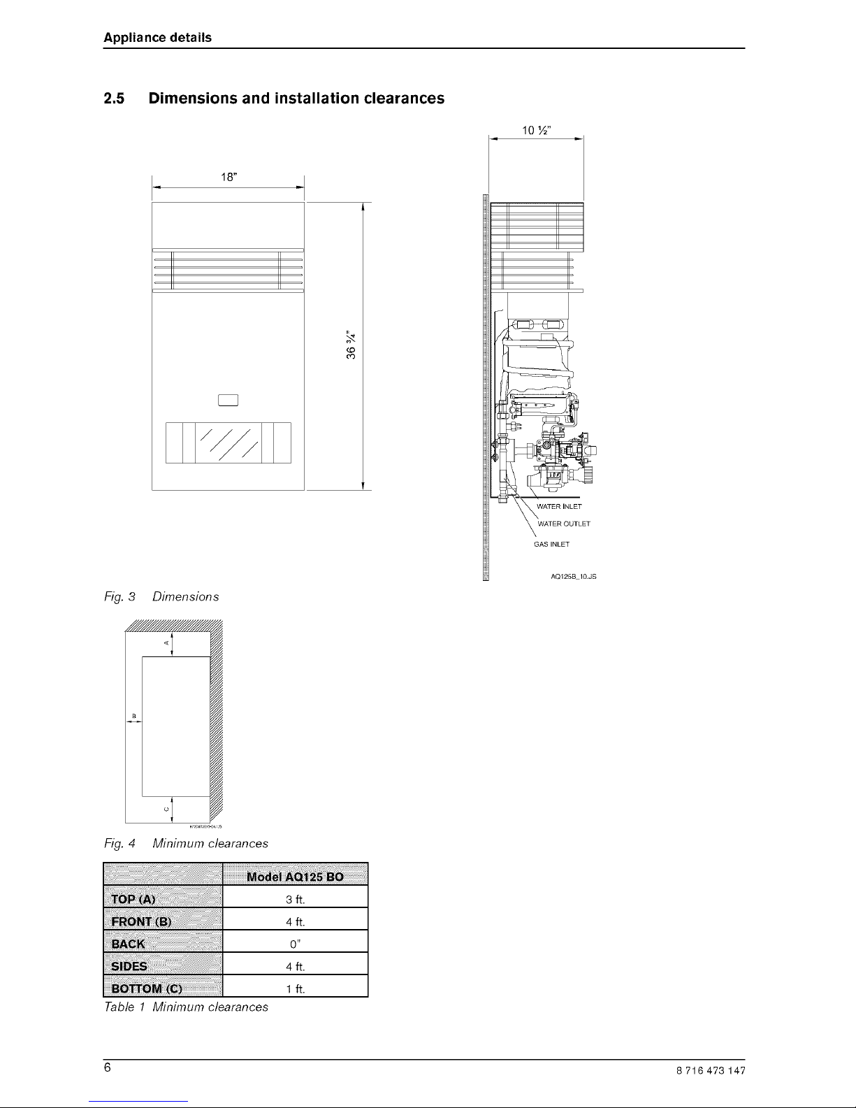
3.3 Heater placement and clearances
The AQ125 BO is design certified for installation
directly on a combustible wall. (see 3.4 Mounting
installation). For installation on vinyl siding see Fig. 7.
Keep the area below the heater free of combustible
material.
Minimum clearances
If the appliance is installed under an overhang, there
must be a 36" clearance from the top of the appliance
and the mounting area must be open in front and on the
sides of the appliance.
Fig. 5
AQ125BO_6
ill i !iiii i¸ _ _ _ _i _ __;_ _ ¸ ;i;
A Directly below or from an
B opening; operable windows, > 4 ft
doors and any fresh air
C openings
D From any adjacent wall or tall > 4 ft
shruberry
E Below a gutter, sanitary > 3 ft
pipework, eaves or overhang
F Above ground > 1 ft
From a gas meter, gas
G regulator, electrical box or > 3 ft
another 125 BO heater.
Table 2 Clearances
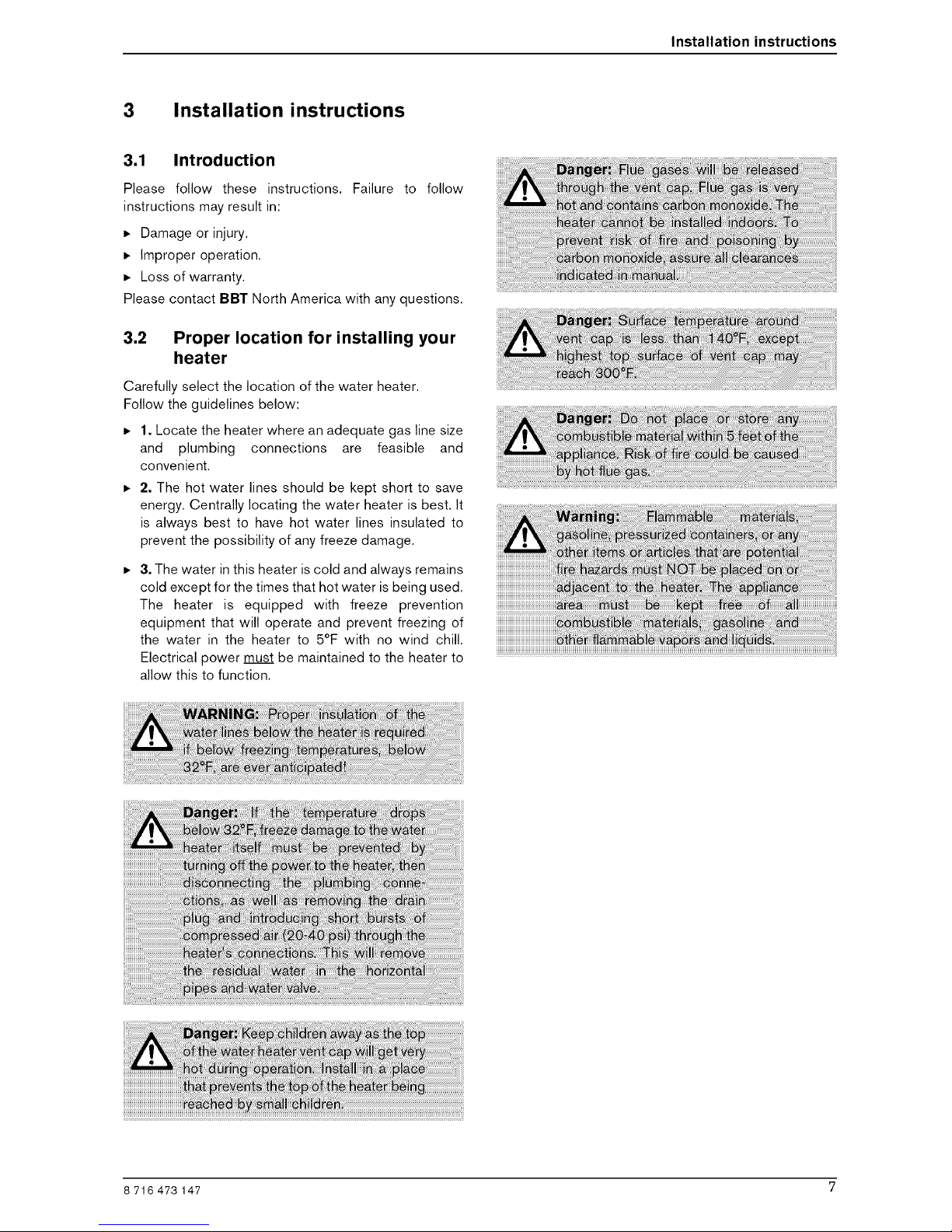
3.4 Mounting installation
Front cover should be removed in order to
inspect components visually (see
instructions below).
To remove front cover.
• Loosen the two screws located on the sides of the
front panel, see Fig. 6.
Fig. 6 Remove front cover
• Ensure that the flue terminal is clear of
combustible material.
• After inspection, replace front cover and tighten
screws.
any
• Install only on an external wall, as close as possible
to the most frequently used hot tap (note clearances
in chapter 3.3).
• If the unit is to be installed on a combustible surface
use the enclosed heat shield (see Fig. 5).
8 8 716 473 147
 Loading...