

Page 1
Engineered Solutions | AMC2 - Access Modular Controller
AMC2 - Access Modular Controller
www.boschsecurity.com
u Intelligent access manager for one to eight
entrances
u Four interfaces include the reader power supply
u Standard 2 GB compact flash
The AMC2 (Access Modular Controller) is used as an
access controller in the access control systems ACE
(ACCESS ENGINE) from version 2.0 onward, Access
Personal Edition, and Access Professional Edition. The
device controls a group of one to eight access points.
These access points, also known as entrances, mainly
consist of doors, gates, barriers, turn stiles, revolving
doors, mantraps, ID card readers, door opening
elements and sensors. The AMC2 can control up to
eight ID card readers (depending on the reader type)
and is designed for fully processing the access logic at
the assigned entrances.
Status checks can be carried out using the eight
analog inputs. The eight relay outputs are used to
activate the door opening elements and/or generate
the security activation and signaling. The AMC2 stores
all necessary information in a battery-buffered memory
and a compact flash storage element so that, even
when the unit is offline, it is able to carry out
independent authorization checks on access points,
take access decisions, control closing/opening
elements and register movement events.
u LCD display for displaying information
u Self-controlling send and receive switching
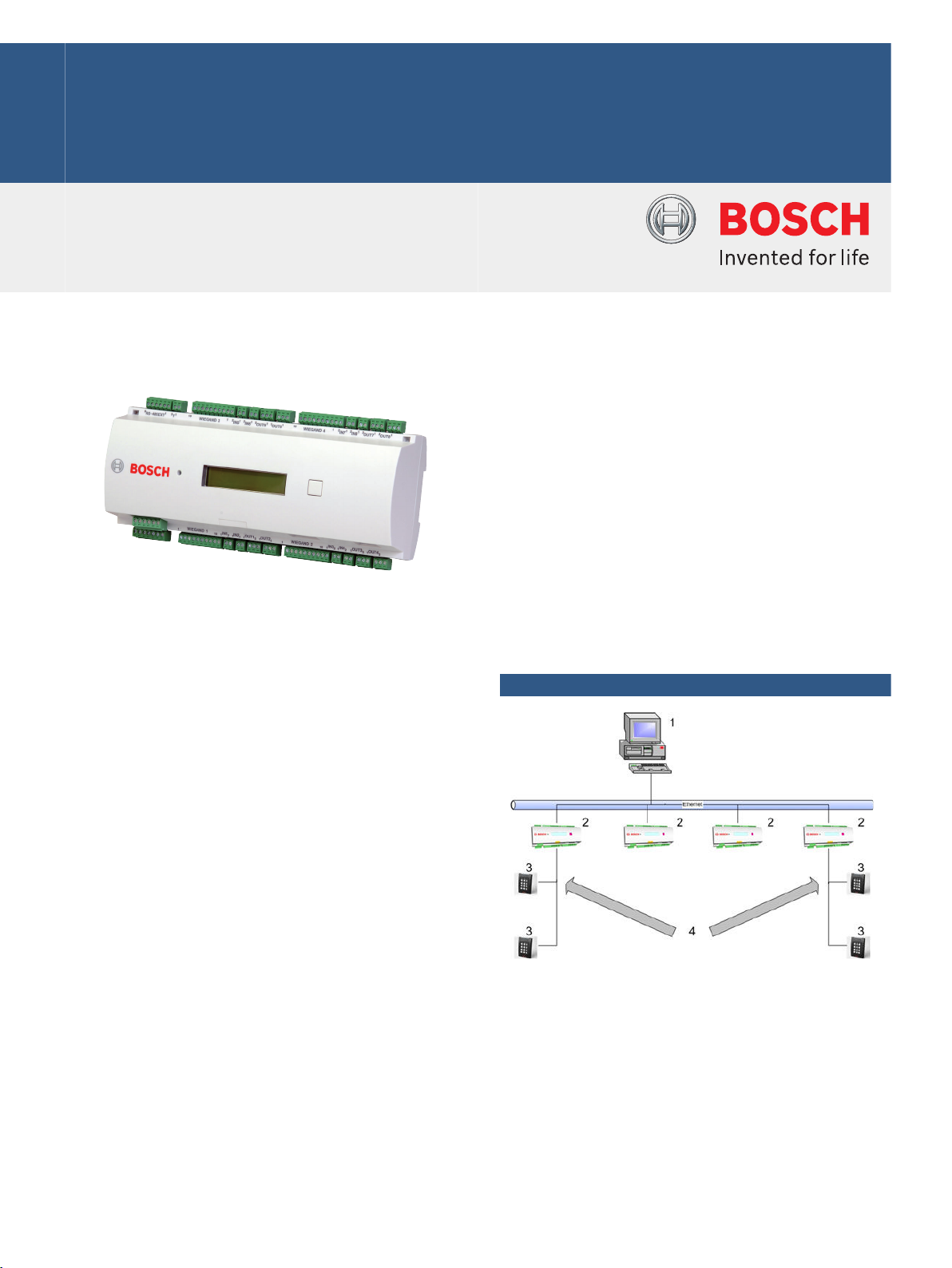
System overview
1 = Host computer
2 = AMC2
3 = Card reader
4 = Communication and power supply
As shown in the diagram, the AMC2 is integrated
between the host system (e.g. Access Engine) and the
peripheral devices.
They are connected to the host system via RS485,
RS232 (e.g. modem operation) or Ethernet, depending
on the size of the system. The relevant host interface
is selected during installation. All three interfaces are
Page 2
| AMC2 - Access Modular Controller
2
available on the device by default. With RS485
operation, a maximum of eight AMC2’s can be
connected to one party line.
There are up to four slots on the peripheral bus for
readers, including the slot for the power supply.
Functions
• Storing downloaded data as listed below:
– Master data
– Authorizations
– Access models
– Display texts
– Reader configurations
• Interpretation of transaction data from reader
– Authorization check
– Host request
– PIN code
• Control/monitoring
– Denial or door release
– Switching alarm
– Door statuses
– Reader operation statuses
– Internal alarm statuses
• Messages to Access Engine
– Host requests
– Transaction data for storing
– Error and malfunction messages
– Alarm messages
• Power supply for
– Readers
– Door openers
– Contact current feeds
Host connections
RS232 host interfaces
The Access Engine application administers up to 32
serial direct connections (ports), theoretically allowing
32 AMC2’s to be directly connected in series.
Notice
Since PCs only have a maximum of two COM
interfaces by default, the following connection
variants are preferable for configurations with
more than two AMC2’s:
Certifications and approvals
Region Certification
Europe CE EC-Declaration of Conformity
EN501312101498_0551-QUA_EMC lEC
60950-1 Safety general
EN501312101498.0552-QUAIEMC EMC Direc-
tive 2004/108/EC
EN50131EN60950 210440750 lEC 60950-1
Safety General
Poland CNBOP 0902 PL_CNBOP 0902
CNBOP 0903 PL_CNBOP 0903
Installation/configuration notes
Power supply
An external power supply (10 to 30 V DC) for the
AMC2 is connected to the first (positive) and third pin
(negative).
When using an uninterruptible power supply (UPS),
the relevant UPS output relay is connected to the pins
• 4 and 7 for alternating current
• 5 and 7 for the battery
• 6 and 7 for direct current
Otherwise, these pins will short-circuit.
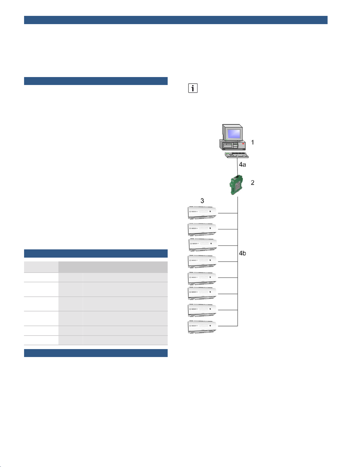
1 = Host computer
2 = RS232/485 AMC-MUX converter
3 = AMC2
4a = RS232 connection
4b = RS485 connection: Up to eight AMC2’s can be
connected to one RS485 interface for each AMC-MUX.
The AMC-MUX interface converter should be used if
more than two AMC2’s are connected.
The interface converter generates an RS485 bus (2 or
4-wire) from a COM port and thus allows up to eight
AMC2’s to be connected with the RS485-typical
distances (1200 m/3900 ft.).
Page 3

| AMC2 - Access Modular Controller
3
Alternatively, the RS485 host interface (2 or 4-wire)
can be activated in the AMC2 via a jumper. There are
two sets of connection points; one for the incoming
and one for the outgoing bus system.
Quantity restrictions
• Please follow the Access Engine installation and
configuration instructions regarding the maximum
number of access controllers on one access control
system and the number of cardholders.
• Max. 4 access points/entrances
• Max. 4 ID card readers
• Max. 3 peripheral devices via internal RS485 bus
• Max. 200,000 cardholders
ID card reader connections
Wiegand interfaces
The AMC2 4W has four connections for connecting up
to four ID card readers.
ID card reader and door control element interfaces are
split into four channels, each with four connection
plugs.
The following definitions apply to the Wiegand
interface:
• 10-wire interface (incl. shield)
• Maximum cable length of 158 m (500 ft.) to ID card
reader
• 26-bit Wiegand format
• 37-bit Wiegand format
Default configuration of the Wiegand interface on the
ID card reader:
1 12V+ reader power supply
2 12V- reader power supply
1 12V+ reader power supply
2 12V- reader power supply
3 Shield
4 Data RxTx+
5 Data RxTx-
6 Data shield (PAG)
7 Not connected
8 Not connected
9 Not connected
10 Not connected
Reader and door models
The AMC2 controls the connected reader via
predefined door models.
Door models govern in accordance with the relevant
security requirements
• Number and usage of the readers connected to the
AMC2, e.g. input and output readers, input readers
and buttons etc.
• Number and application type of the AMC inputs, e.g.
door status, output button, revolving door position,
GMA etc.
• Number and usage of AMC outputs, e.g. door opener,
mantrap contact, signal light switching etc.
The maximum number of entrances to be managed by
one AMC2 is ultimately defined by the door models
used and their requirements regarding readers and
inputs/outputs.
3 Data line 0
4 Data line 1
5 Shield
6 Green LED
7 Red LED
8 Acoustic signal
9 Delay
10 Show card
RS485 interfaces
The AMC2 4R4 has four connections for connecting up
to eight ID card readers. The interfaces are divided to
two busses – all possible readers (up to eight) can be
connected to one interface.
RS485 interface definition:
• 2-wire interface: Using the 10-pin pluggable
connector.
• Max. length of the bus: 1200 m
• Transfer rates: 9,6 or 19,2 kBit/s
Default configuration of the Rs485 interface on the ID
card reader:
Notice
Therefore, when planning an access system, you
must first assign the relevant door models to all
entrances that are to be controlled. Only then can
you configure the AMC reader.
Voltage equalization - grounding
• Different voltages can be equalized using jumpers
with protective ground.
• A line (shield, equipotential bonding line) with
protective ground can only be connected in one
position.
• For further instructions, please see the operating
manual!
Contacts
Inputs
The eight analog inputs can be used as digital or
analog contacts. For analog use, resistance values can
be specified that make it possible to carry out a
further check for cable breaks and short-circuits.
Relay outputs
The relay outputs offer the following functions:
• The outputs can operate with potential free contacts
for external power supply (dry mode).
Page 4

4 | AMC2 - Access Modular Controller
• The outputs can operate using the internal voltage of
power supply (wet mode).
• Only ohm resistive loads can be connected to the
relay.
• Inductive loads must be bypassed via recovery
diodes. These diodes (1N4004) are enclosed.
General instructions
• AMC2 and related equipment should be mounted in a
"secured area".
• Detailed connection conditions are specified in the
operating manual!
• After purchase, primary AC power must be carried
out by a licensed electrician.
Technical specifications
Hardware CPU RENESAS M32C84
512 kB-EPROM/FLASH
256 kB-SRAM
Serial EEPROM
RTC
Pluggable 2 GB compact flash
Battery for SRAM and RTC
Host address can be set via sliding switch
Host interface:
4 reader interfaces:
8 relay outputs:
8 monitored analog inputs
Tamper switch
Reset button
Temperature 0°C to +45°C (32°F to 113°F)
Power supply 10 to 30 VDC, max. 60 VA
Environment
class
Housing Base: PPO (UL 94 V-0)
Integrated Microcontroller (32Bit, 30MHz)
- RS485 (2- or 4-wire); opto-decoupled
- RS232
- Ethernet 10/100BaseT (TCP/IP) with RJ45
- Wiegand or
- RS-485, 2-wire, opto-coupled, 19.200 Bd
- max. switching voltage: 30 V DC
- max. switching current: 1,25 A
Available for external devices: 55 VA
IP 30
Upper: Polycarbonate (UL 94 V-0)
Ordering information
AMC2 4W-NET-CF - Wiegand Interfaces
Four Wiegand card reader interfaces, network
connection to the host system and Compact Flash
memory (2 GB).
Order number APC-AMC2-4WCF
AMC2 4W-NET-CF - Wiegand Interfaces
Four Wiegand card reader interfaces, network
connection to the host system and Compact Flash
memory (2 GB).
Order number ADS-AMC2-4WCF
AMC2 4R4-CF - RS-485 Interfaces
Four RS-485 card reader interfaces, network
connection to the host system and Compact Flash
memory (2 GB).
Order number APC-AMC2-4R4CF
AMC2 4R4-CF - RS-485 Interfaces
Four RS-485 card reader interfaces, network
connection to the host system and Compact Flash
memory (2 GB).
Order number ADS-AMC2-4R4CF
AMC2 8I-8O-EXT
8 input/output extension board, up to three per AMC,
can be combined with the AMC2 16I-EXT and the
AMC2 16I-16O-EXT
Order number API-AMC2-8IOE
AMC2 8I-8O-EXT
8 input/output extension board, up to three per AMC,
can be combined with the AMC2 16I-EXT and the
AMC2 16I-16O-EXT
Order number ADS-AMC2-8IOE
AMC2 16I-16O-EXT
16 input/output extension board, up to three per AMC,
can be combined with the AMC2 16I-EXT and the
AMC2 8I-8O-EXT
Order number API-AMC2-16IOE
AMC2 16I-16O-EXT
16 input/output extension board, up to three per AMC,
can be combined with the AMC2 16I-EXT and the
AMC2 8I-8O-EXT
Order number ADS-AMC2-16IOE
AMC2 16I-EXT
16 input extension board, up to three per AMC, can be
combined with the AMC2 16I-16O-EXT and the AMC2
8I-8O-EXT
Order number API-AMC2-16IE
Color White
Dimensions WxHxD: 232 x 90 x 63 mm (9.13 x 3.54 x 2.48 in.)
Weight Approx. 0.53 kg (1.17 lb)
Type Rail mounting
AMC2 16I-EXT
16 input extension board, up to three per AMC, can be
combined with the AMC2 16I-16O-EXT and the AMC2
8I-8O-EXT
Order number ADS-AMC2-16IE
Page 5

5 | AMC2 - Access Modular Controller
AMC2-16ION
Standalone Controller with inputs and outputs, only.
Order number API-AMC2-16ION
AMC2-16ION
Controller with inputs and outputs, only.
Order number ADS-AMC2-16ION
Accessories
AMC2 4W-EXT - Wiegand Extension Board
The extension module AMC2 4W-EXT is equipped with
four Wiegand type reader-interfaces plus eight inputs
and eight outputs. Hence with the AMC2 4W-EXT it is
possible to double the number of readers on an AMC2
4W from 4 to 8.
Order number API-AMC2-4WE
AMC2 4W-EXT - Wiegand Extension Board
The extension module AMC2 4W-EXT is equipped with
four Wiegand type reader-interfaces plus eight inputs
and eight outputs. Hence with the AMC2 4W-EXT it is
possible to double the number of readers on an AMC2
4W from 4 to 8.
Order number ADS-AMC2-4WE
AMC2 ENC-EMEA - Enclosure
This enclosure is used for securely mounting and
housing the AMC2 and a power supply (e.g. AMC
PBC60).
Order number AEC-AMC2-EMEA01
AMC RAIL-250 mounting rail
Mounting rail (250 mm) for mounting the access
controller AMC-4W without the metal housing AMC
ENC-V1.
Order number ACX-RAIL-250
AMC RAIL-400 mounting rail
Mounting rail (400 mm) for mounting the AMC-4W,
AMC PS-12V-60W and AMC UPS-12V when the metal
housing AMC ENC-V1 is not used.
Order number ACX-RAIL-400
AMC-MUX interface converter
Interface converter – RS-232 into RS-485/422
Order number ACX-AMC-MUX
AMC-MUX-EXT interface extension
An extension module for the AMC-MUX to create a
network star topology.
Order number ACX-AMC-MUXE
AMC2 ENC-UL1 - Enclosure - Small
AMC2 enclosure with single din rail.
Order number AEC-AMC2-UL1
AMC2 ENC-UL2 - Enclosure - Large
AMC2 enclosure with two din rails.
Order number AEC-AMC2-UL2
AEC-PANEL19-4DR - Mounting plate with four DIN rails
Mounting plate with four DIN rails for 19” racks to
connect max. four AMC2 devices.
Order number AEC-PANEL19-4DR
AEC-PANEL19-UPS - Mounting plate with two DIN rails
Mounting plate with two DIN rails, a battery bracket,
and screw sockets for the power supply to mount into
19” racks.
Order number AEC-PANEL19-UPS
PBC-60 - power supply and battery charger
A power supply unit with an integrated battery
charging device.
Order number APS-PBC-60
Gel Battery 12 V / 7.2 Ah
(DU = 1 unit)
Order number IPP-12V-7.2Ah
Page 6

6 | AMC2 - Access Modular Controller
Represented by:
Americas: Europe, Middle East, Africa: Asia-Pacific: China: America Latina:
Bosch Security Systems, Inc.
130 Perinton Parkway
Fairport, New York, 14450, USA
Phone: +1 800 289 0096
Fax: +1 585 223 9180
security.sales@us.bosch.com
www.boschsecurity.us
Bosch Security Systems B.V.
P.O. Box 80002
5617 BA Eindhoven, The Netherlands
Phone: + 31 40 2577 284
Fax: +31 40 2577 330
emea.securitysystems@bosch.com
www.boschsecurity.com
Robert Bosch (SEA) Pte Ltd, Security
Systems
11 Bishan Street 21
Singapore 573943
Phone: +65 6571 2808
Fax: +65 6571 2699
apr.securitysystems@bosch.com
www.boschsecurity.asia
Bosch (Shanghai) Security Systems Ltd.
201 Building, No. 333 Fuquan Road
North IBP
Changning District, Shanghai
200335 China
Phone +86 21 22181111
Fax: +86 21 22182398
www.boschsecurity.com.cn
Robert Bosch Ltda Security Systems Division
Via Anhanguera, Km 98
CEP 13065-900
Campinas, Sao Paulo, Brazil
Phone: +55 19 2103 2860
Fax: +55 19 2103 2862
latam.boschsecurity@bosch.com
www.boschsecurity.com
© Bosch Security Systems 2013 | Data subject to change without notice
1353287819 | en, V3, 21. Oct 2013
 Loading...