

Page 1

UDS1100 Start Guide for AEC2.1
AIM-AEC21-CVT
en Quick Start Guide
Page 2

Page 3

UDS1100 Start Guide for AEC2.1 Table of Contents | en 3
Table of Contents
1 Introduction 4
2 Installing UDS1100 5
3 Setting up the converter 9
Robert Bosch (SEA) Pte Ltd Quick Start Guide F01U168574 | 1.0.0 | 2010.06
Page 4
4 en | Introduction UDS1100 Start Guide for AEC2.1
1 Introduction
This guide explains how to connect and configure the UDS1100 Lantronix
converter with AEC2.1. When the UDS1100 converter’s Ethernet network
port is linked to AEC2.1 CPU LAN port, it provides an additional multi-drop
communication channel, RS485 to interface up to four 4 reader board and
four 8 input-output board. This document shows the connections to the
AEC2.1’s CPU and interface boards.
The UDS1100 converter support requires AEC2.1 firmware version 2.1.6.0
onwards. Please check our online AEC software upgrade at
http://www.boschsecurity.us/en-us/aec.
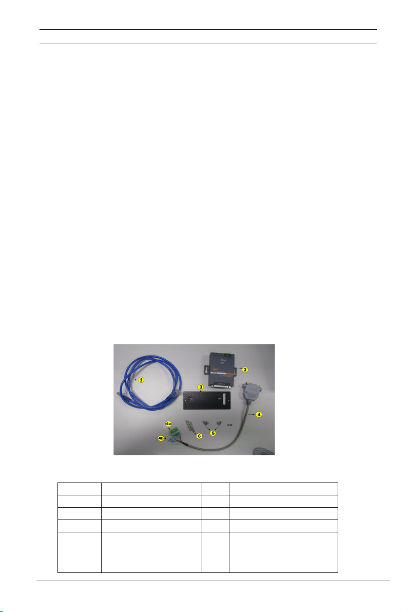
What’s in the box?
The AIM-AEC21-CVT box comes with the converter UDS1100, power
supply, serial cable & CD ROM containing User guide and software utilities
and Quick Start Guide from Lantronix. It also contains:
– Network cable - cross type
– A serial cable to connect to the RS485 port of AEC2.1’s board
– A mounting plate with screws to mount UDS1100 on the panel
– A start guide
Figure 1.1 Components
No. Description No. Description
1 Network cable 5 Screws
2 UDS1100 6 Metal standoffs
3 Metal plate
4
4a
4b
F01U168574 | 1.0.0 | 2010.06 Quick Start Guide Robert Bosch (SEA) Pte Ltd
Serial cable
Power terminal block
RS485 cable
Page 5

UDS1100 Start Guide for AEC2.1 Installing UDS1100 | en 5
2 Installing UDS1100
The converter can be connected in two ways-either on a top of the reader
board next to CPU (refer to Figure 2.6) or place the converter on another
extension panel (refer to Figure 2.7).
For mounting the converter on the reader board follow the instructions
below:
1. Install two metal standoffs on the reader board.
Figure 2.1 Reader board with metal standoffs
No Description
1 Metal standoffs
2. Place and align the metal plate over the two metal standoffs. Place the
machine screw and the flat plastic washer on the two allotted holes as
shown in Figure 2.2.
Figure 2.2 Machine screw with plastic washer
No Description
1 Metal screw
2 Plastic washer
Figure 2.3 Mounting plate with the screw direction
Robert Bosch (SEA) Pte Ltd Quick Start Guide F01U168574 | 1.0.0 | 2010.06
Page 6

6 en | Installing UDS1100 UDS1100 Start Guide for AEC2.1
Secure the metal plate by tightening the screws rotating in the direction
shown by the arrow in Figure 2.3.
3. Place and align the converter on the metal plate according to the
slots. Place the machine screw on the two allotted holes as shown in
Figure 2.4. Secure the converter by tightening the screws.
Figure 2.4 Converter mounted on plate with screw directions
4. Connect the network cable and the serial cable(RS485) in the allotted
slots as shown in Figure 2.5. The RS485 serial cable is connected to
the AEC2.1’s reader or I/O board. The network cable of the converter
is connected to the LAN 2 port of the AEC2.1’s CPU.
Figure 2.5 Network cable and serial cable connection points
No Description
1 Network cable
2 Serial cable
F01U168574 | 1.0.0 | 2010.06 Quick Start Guide Robert Bosch (SEA) Pte Ltd
Page 7

UDS1100 Start Guide for AEC2.1 Installing UDS1100 | en 7
Figure 2.6 Wiring connections with converter next to AEC2.1 CPU
No Description
1 Power terminal for serial cable
2 RS485 connection to another reader/input-output board
3 Network cable connection to LAN port 2
Figure 2.7 Alternative wiring connections of the converter
No Description
1 A and B (RS485)
2Main power
3 Out+ and Out4Tamper switch
Robert Bosch (SEA) Pte Ltd Quick Start Guide F01U168574 | 1.0.0 | 2010.06
Page 8
8 en | Installing UDS1100 UDS1100 Start Guide for AEC2.1
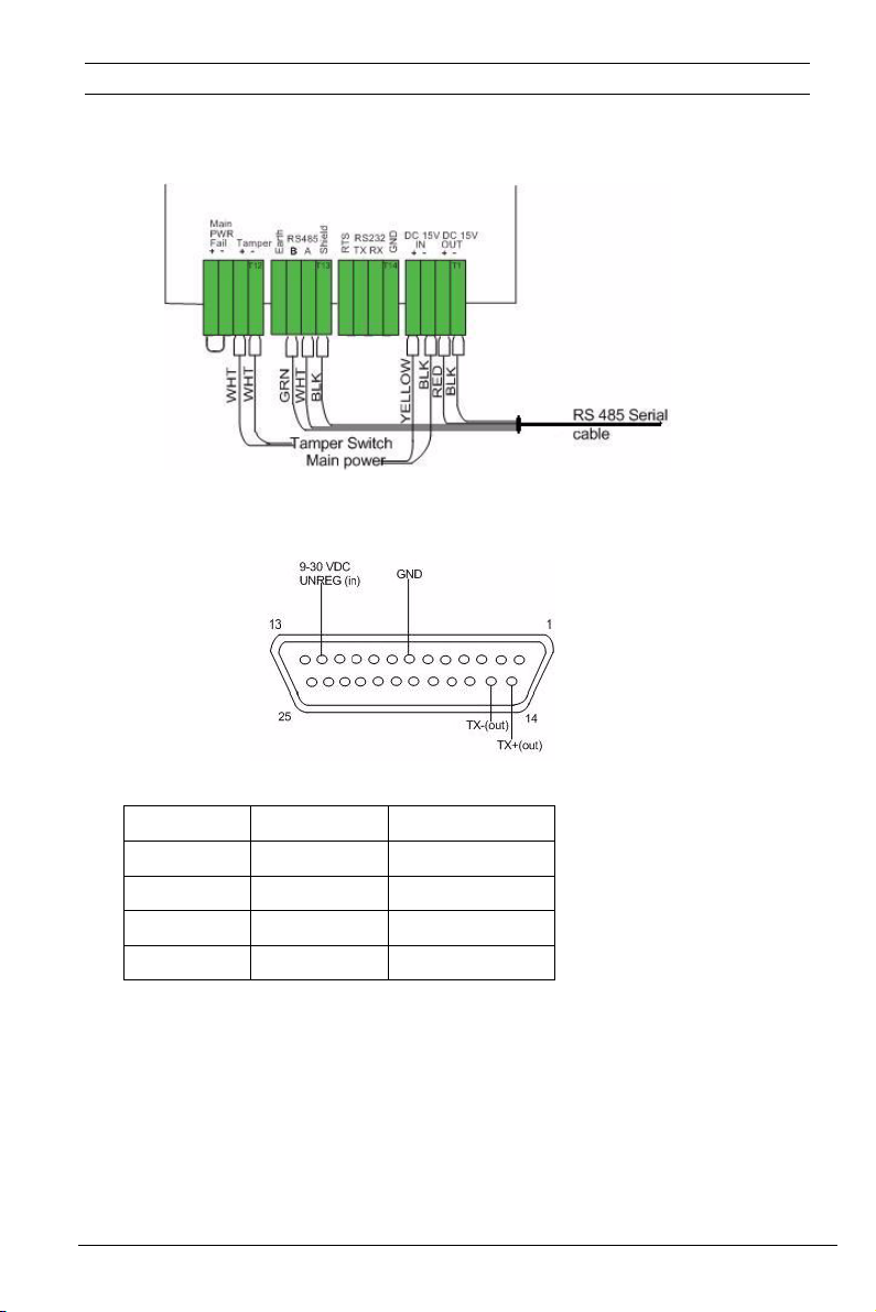
Figure 2.8 shows the detailed wiring illustrating the coloured wire points
including the RS485 cable, main power and tamper switch.
Figure 2.8 Detailed wiring(illustrating color wires and input points)
Figure 2.9 PINOUTS of RS485 serial cable
PIN AEC’s board Colour wires
14(TX+) RS485 A White
15(TX-) RS485 B Green
12(VDC) DC Out+ Red
7(GND) DC Out- Black
F01U168574 | 1.0.0 | 2010.06 Quick Start Guide Robert Bosch (SEA) Pte Ltd
Page 9

UDS1100 Start Guide for AEC2.1 Setting up the converter | en 9
3 Setting up the converter
The Bosch pre-configured device, AIM-AEC2.1-CVT does not require any
further configuration.
Do the following steps for advance setup:
1. If it is users defined/changing IP address to the converter follow steps
1 and 3.
2. If using original UDS1100 default setting from Lantronix, follow steps
1 to 3.
Step 1: The pre-configured IP address is 192.168.2.42 and the Subnet
Mask is 255.255.255.0. Users can manually assign an IP address to the
UDS1100, (refer to the Quick Start Guide from Lantronix).
Figure 3.1 Network settings
Login the UDS1100 via a web browser as shown in Figure 3.1, to reassign
the IP address. After changing the settings click on apply settings.If the
UDS1100 for AEC2.1 is from Bosch, it comes with pre-configured network
settings to RS485.
Robert Bosch (SEA) Pte Ltd Quick Start Guide F01U168574 | 1.0.0 | 2010.06
Page 10

10 en | Setting up the converter UDS1100 Start Guide for AEC2.1
Step 2: Set the port settings and pack control in the serial settings page.
Select RS485-2wire in the protocol drop down box. The Baud Rate is
19200, Data bits is 8 and Stop bits is 2. The value for Flow Control and
Parity is set to none. The Idle Gap Time in the pack control is set to
12msec. Click on the apply settings.
Figure 3.2 Serial settings
Step 3: Login to the AEC 2.1 and set up the LAN converter IP Address. Key
in the IP address of the UDS1100 converter.
Figure 3.3 AEC2.1 LAN converter setting
F01U168574 | 1.0.0 | 2010.06 Quick Start Guide Robert Bosch (SEA) Pte Ltd
Page 11

Page 12

Robert Bosch (SEA) Pte Ltd
11 Bishan Street 21
573943 Singapore
Singapore
www.boschsecurity.com
© Robert Bosch (SEA) Pte Ltd , 2010
 Loading...