

Bontrager Duotrap S User Manual
• •
DUOTRAP S
ANT+ and Bluetooth Smart Dual Mode
Integrated Speed and Cadence Sensor
•
1
•
2
•
4
•
5
•
1
•
•
2
4
•
1
m
2.5N
MADE IN CHINA
•
3
•
6
m2.5N
•
C
R
2
0
3
2
a
b
•
3
•
2
5
4
4
a
b
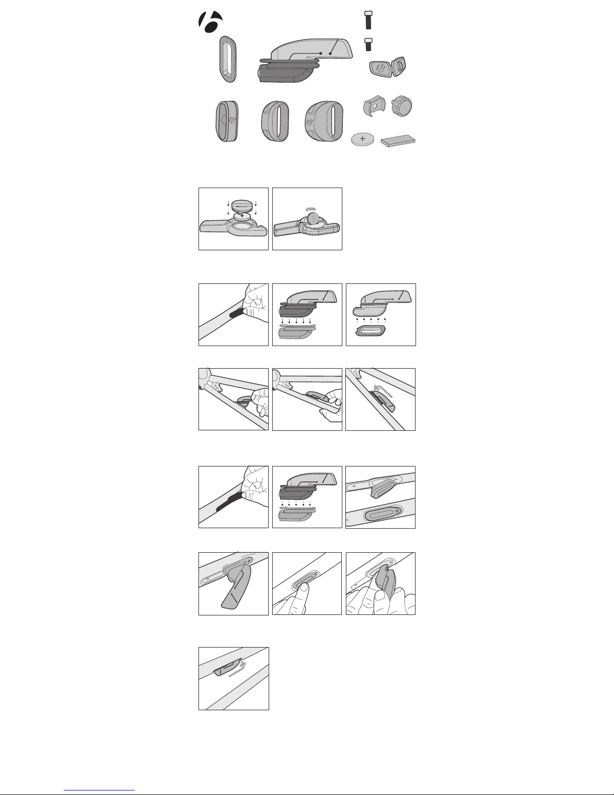
SENSOR INSTALLATION (ALLOY BIKES)
SENSOR INSTALLATION (CARBON BIKES)
BATTERY INSTALLATION AND REPLACEMENT
Gasket (alloy bikes)
Remove DuoTrap S cover
from chainstay.
Remove DuoTrap S cover
from chainstay.
Medium cadence
magnet band
(crank)
Install sensor into chainstay.
While holding sensor in
place, use a 2.5mm hex to
tighten 6mm short screw.
Note: 6mm screw must be
used with carbon frames.
Remove grommet and
replace with gasket in #3.
Remove grommet.
Hold sensor into place and
install 8mm long screw.
Install sensor into grommet in the chainstay. Hint: Hold
grommet in place with one hand while inserting sensor with
the other as seen in pic 4a and 4 b.
Replacement battery
CR2032.
Use a coin to close battery
compartment.
Install gasket onto sensor
with notch aligned with
screw hole as depicted
Fully insert grommet into
chainstay resulting in a flush
connection with chainstay.
While holding sensor in
place, use a 2.5mm hex to
tighten 8mm long screw.
Sensor with grommet (carbon bikes)
8mm alloy
bike mounting
screw
6mm carbon
bike mounting
screw
Small cadence
magnet band
(crank)
Large cadence
magnet band
(crank)
CR2032
battery
Alloy bike speed
magnet (wheel)
Cadence band
shim (optional)
Carbon bike speed
magnet (wheel)
•
1
•
2
•
2
•
3
•
1
•
•
3
4
NOTE: This equipment has been tested and found to comply with the limits for a Class B
digital device, pursuant to Part 15 of the FCC Rules. These limits are designed to provide
reasonable protection against harmful interference in a residential installation. This
equipment generates uses and can radiate radio frequency energy and, if not installed
and used in accordance with the instructions, may cause harmful interference to radio
communications. However, there is no guarantee that interference will not occur in a
particular installation.
If this equipment does cause harmful interference to radio or television reception, which
can be determined by turning the equipment off and on, the user is encouraged to try to
correct the interference by one or more of the following measures:
-- Reorient or relocate the receiving antenna.
-- Increase the separation between the equipment and receiver.
-- Connect the equipment into an outlet on a circuit different from
that to which the receiver is connected.
-- Consult the dealer or experienced radio / TV technician for help.
NOTES:
THE MANUFACTURER IS NOT RESPONSIBLE FOR ANY RADIO OR TV INTERFERENCE
CAUSED BY UNAUTHORIZED MODIFICATIONS TO THIS EQUIPMENT. ANY CHANGES
OR MODIFICATIONS NOT EXPRESSLY APPROVED BY THE GRANTEE OF THIS DEVICE
COULD VOID THE USER’S AUTHORITY TO OPERATE THE DEVICE.
Pairing: Consult your ANT + or Bluetooth Smart device’s instructions for pairing. Sensor
will need to be activated directly before pairing process.
Sensor Activation: To verify proper magnet install, spin wheel or turn crank more than
two revolutions. Initial sensor activation and magnet alignment will be indicated by the
LEDs flashing up to 10 times.
Please Note: The sensor will stay active for at least 2 minutes although the LEDs no
longer flash.
Bluetooth Smart Connection: Install and activate sensor. Turn on your phone’s
(or other compatible device) Bluetooth capability. Open the desired cycling app and follow
instructions for Bluetooth Smart sensor connection. Please note, Bluetooth Smart devices
do not always appear in your phone’s settings, even when connected. All apps collect,
share, and display speed and cadence information differently.
FCC ID: 04GDUOTRAPS
This device complies with part 15 of the FCC Rules.
Operation is subject to the following conditions:
(1) this device may not cause harmful interference, and
(2) this device must accept any interference received, including
interference that may cause undesired operation.
This device complies with Industry Canada RSS standard(s). Operation is subject to the
following two conditions: (1) this device may not cause interference, and (2) this device
must accept any interference, including interference that may cause undesired operation
of the device.
Leprésent appareil est conforme aux CNR d’Industrie Canada applicable aux appareils
radio. Exempts de licence. L’exploitation est autorisée aux deux conditions suivantes: (1)
l’appareil ne doit pas produire de brouillage, et (2) l’utilsateur de l’appareil doit accepter
tout brouillage radioélectrque subi, meme si le brouillage est susceptible d’en
compromettre le fonctionnement.
www.bontrager.com
IC: 7666A-DUOTRAPS
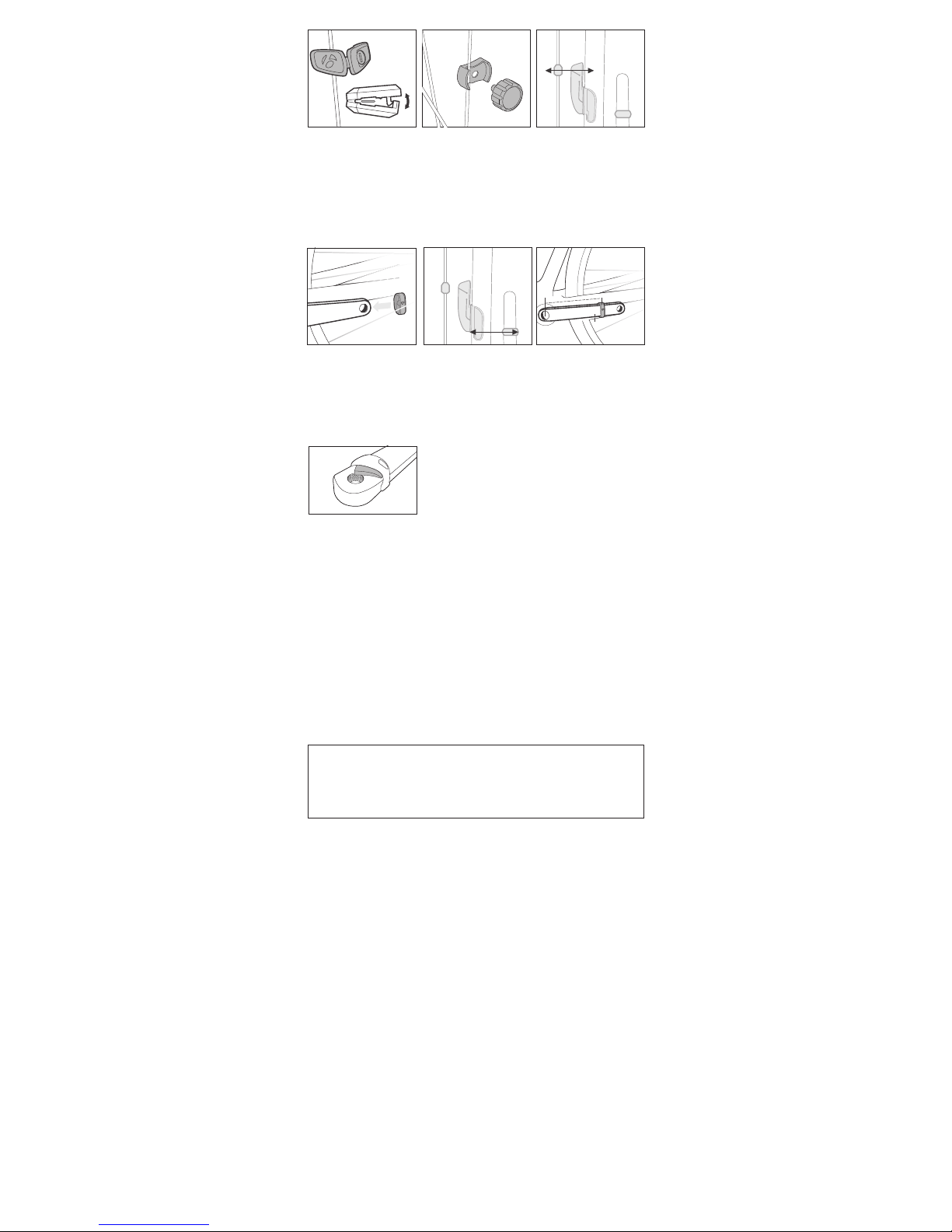
Remove the pedal and
install cadence magnet on
nondrive side crank arm
with thick side nearer the
chainstay. Use cadence
magnet band that gives
the best fit.
For carbon bikes, place
magnet 135mm or
145mm from the center
of the bottom bracket to
the center of the magnet.
Hint: If the magnet is aligned
but the LED does not
illuminate, place a cadence
band shim underneath the
appropriate magnet.
Verify magnet is aligned with
sensor by illumination of
green cadence sensor LED
as crank is turned. LED will
illuminate for the first 10
revolutions. Align magnet
with tech mark on alloy
bike’s chain stay.
145mm
135mm
SPEED MAGNET INSTALLATION (CARBON AND ALLOY BIKES)
CADENCE MAGNET INSTALLATION (CARBON AND ALLOY BIKES)
PAIRING AND SENSOR ACTIVATION
Speed magnet (carbon
bikes) Snap magnet onto
inside/trailing edge non-drive
side spoke. Some carbon
frame/wheel combinations
may require magnet to be
flipped so the thin side faces
sensor.
Speed magnet (alloy bikes)
Tighten wheel magnet on
spoke for alloy bikes
Align speed magnet with
tech mark on DuoTrap S.
Verify sensor is aligned with
magnet by illumination of red
speed sensor LED as wheel
is rotated. LED will illuminate
for the first 10 revolutions.
 Loading...