


Table of Contents
N74 Engine
Subject Page
Introduction . . . . . . . . . . . . . . . . . . . . . . . . . . . . . . . . . . . . . . . . . . . . . . . . . .5
N74 Engine . . . . . . . . . . . . . . . . . . . . . . . . . . . . . . . . . . . . . . . . . . . . . . . . . . . .5
History . . . . . . . . . . . . . . . . . . . . . . . . . . . . . . . . . . . . . . . . . . . . . . . . . . . . . . . .6
N74 Engine Features . . . . . . . . . . . . . . . . . . . . . . . . . . . . . . . . . . . . . . . . . . .7
Technical Data . . . . . . . . . . . . . . . . . . . . . . . . . . . . . . . . . . . . . . . . . . . . . . . . .8
Horse Power and Torque Diagram . . . . . . . . . . . . . . . . . . . . . . . . . . . .10
Engine Components/Systems Overview . . . . . . . . . . . . . . . . . . . . . . .11
Engine Identification . . . . . . . . . . . . . . . . . . . . . . . . . . . . . . . . . . . . . . . .13
Engine designation . . . . . . . . . . . . . . . . . . . . . . . . . . . . . . . . . . . . . .13
Engine identification and number . . . . . . . . . . . . . . . . . . . . . . . . . .13
Engine Components . . . . . . . . . . . . . . . . . . . . . . . . . . . . . . . . . . . . . . . . .14
Engine Block . . . . . . . . . . . . . . . . . . . . . . . . . . . . . . . . . . . . . . . . . . . . . . . . .14
Cylinder Head . . . . . . . . . . . . . . . . . . . . . . . . . . . . . . . . . . . . . . . . . . . . . . . . .15
Cylinder Head Cover . . . . . . . . . . . . . . . . . . . . . . . . . . . . . . . . . . . . . . . .15
Oil Sump . . . . . . . . . . . . . . . . . . . . . . . . . . . . . . . . . . . . . . . . . . . . . . . . . . . . .15
Crankcase Ventilation . . . . . . . . . . . . . . . . . . . . . . . . . . . . . . . . . . . . . . . . . .16
Register Ventilation . . . . . . . . . . . . . . . . . . . . . . . . . . . . . . . . . . . . . . . . . .18
Oil Separation . . . . . . . . . . . . . . . . . . . . . . . . . . . . . . . . . . . . . . . . . . . . . .19
Crankshaft . . . . . . . . . . . . . . . . . . . . . . . . . . . . . . . . . . . . . . . . . . . . . . . . . . . .20
Crankshaft Bearings . . . . . . . . . . . . . . . . . . . . . . . . . . . . . . . . . . . . . . . . .20
Connecting Rods . . . . . . . . . . . . . . . . . . . . . . . . . . . . . . . . . . . . . . . . . . . . . .20
Pistons . . . . . . . . . . . . . . . . . . . . . . . . . . . . . . . . . . . . . . . . . . . . . . . . . . . . . . .20
Camshaft . . . . . . . . . . . . . . . . . . . . . . . . . . . . . . . . . . . . . . . . . . . . . . . . . . . .20
Chain Tensioner . . . . . . . . . . . . . . . . . . . . . . . . . . . . . . . . . . . . . . . . . . . . . . .20
Valve Train . . . . . . . . . . . . . . . . . . . . . . . . . . . . . . . . . . . . . . . . . . . . . . . . . . . .21
VANOS . . . . . . . . . . . . . . . . . . . . . . . . . . . . . . . . . . . . . . . . . . . . . . . . . . . .22
Camshafts . . . . . . . . . . . . . . . . . . . . . . . . . . . . . . . . . . . . . . . . . . . . . . . . .22
Roller Cam Followers . . . . . . . . . . . . . . . . . . . . . . . . . . . . . . . . . . . . . . . .22
Valves . . . . . . . . . . . . . . . . . . . . . . . . . . . . . . . . . . . . . . . . . . . . . . . . . . . . .22
Belt Drive . . . . . . . . . . . . . . . . . . . . . . . . . . . . . . . . . . . . . . . . . . . . . . . . . .23
Oil Supply . . . . . . . . . . . . . . . . . . . . . . . . . . . . . . . . . . . . . . . . . . . . . . . . . . . .25
Oil Circuit . . . . . . . . . . . . . . . . . . . . . . . . . . . . . . . . . . . . . . . . . . . . . . . . . .25
Oil Pump . . . . . . . . . . . . . . . . . . . . . . . . . . . . . . . . . . . . . . . . . . . . . . . . . .27
Pressure Limiting Valve . . . . . . . . . . . . . . . . . . . . . . . . . . . . . . . . . . . . . .28
Oil Filter . . . . . . . . . . . . . . . . . . . . . . . . . . . . . . . . . . . . . . . . . . . . . . . . . . .28
Initial Print Date: 12/09
Revision Date: 08/10

Subject Page
Oil Cooling . . . . . . . . . . . . . . . . . . . . . . . . . . . . . . . . . . . . . . . . . . . . . . . . .28
Oil Spray Nozzles . . . . . . . . . . . . . . . . . . . . . . . . . . . . . . . . . . . . . . . . . . .28
Oil spray nozzles for piston crown cooling . . . . . . . . . . . . . . . . . . .29
Oil spray nozzles for timing chain lubrication . . . . . . . . . . . . . . . .29
Oil Level Measurement . . . . . . . . . . . . . . . . . . . . . . . . . . . . . . . . . . . . . .29
Engine Cooling . . . . . . . . . . . . . . . . . . . . . . . . . . . . . . . . . . . . . . . . . . . . . . . .30
Coolant Pumps . . . . . . . . . . . . . . . . . . . . . . . . . . . . . . . . . . . . . . . . . . . . .32
Main coolant pump . . . . . . . . . . . . . . . . . . . . . . . . . . . . . . . . . . . . . .32
Auxiliary water pump for exhaust turbochargers . . . . . . . . . . . . . .32
Expansion Tank . . . . . . . . . . . . . . . . . . . . . . . . . . . . . . . . . . . . . . . . . . . . .32
Charge Air Cooling . . . . . . . . . . . . . . . . . . . . . . . . . . . . . . . . . . . . . . . . . . . .33
Auxiliary Coolant Pump for Charge Air Cooling . . . . . . . . . . . . . . . . .35
Charge-air Cooler . . . . . . . . . . . . . . . . . . . . . . . . . . . . . . . . . . . . . . . . . . .35
Engine Control Unit . . . . . . . . . . . . . . . . . . . . . . . . . . . . . . . . . . . . . . . . .36
Intake Air Duct . . . . . . . . . . . . . . . . . . . . . . . . . . . . . . . . . . . . . . . . . . . . . . . .36
Turbocharging . . . . . . . . . . . . . . . . . . . . . . . . . . . . . . . . . . . . . . . . . . . . . . . .37
Exhaust Turbocharger . . . . . . . . . . . . . . . . . . . . . . . . . . . . . . . . . . . . . . .37
Charging Pressure Control . . . . . . . . . . . . . . . . . . . . . . . . . . . . . . . . . . .39
Blow-off control . . . . . . . . . . . . . . . . . . . . . . . . . . . . . . . . . . . . . . . . . .39
Charge Air Cooling . . . . . . . . . . . . . . . . . . . . . . . . . . . . . . . . . . . . . . . . . .40
Intake Manifold . . . . . . . . . . . . . . . . . . . . . . . . . . . . . . . . . . . . . . . . . . . . . . . .40
Exhaust System . . . . . . . . . . . . . . . . . . . . . . . . . . . . . . . . . . . . . . . . . . . . . . .41
Exhaust Manifold . . . . . . . . . . . . . . . . . . . . . . . . . . . . . . . . . . . . . . . . . . .42
Exhaust Emissions . . . . . . . . . . . . . . . . . . . . . . . . . . . . . . . . . . . . . . . . . .42
Secondary Air System . . . . . . . . . . . . . . . . . . . . . . . . . . . . . . . . . . . . . . .42
Secondary air pump . . . . . . . . . . . . . . . . . . . . . . . . . . . . . . . . . . . . . .42
Secondary air valve . . . . . . . . . . . . . . . . . . . . . . . . . . . . . . . . . . . . . . .43
On-board diagnosis of secondary air system . . . . . . . . . . . . . . . .43
Vacuum System . . . . . . . . . . . . . . . . . . . . . . . . . . . . . . . . . . . . . . . . . . . . . . .44
Fuel Injection . . . . . . . . . . . . . . . . . . . . . . . . . . . . . . . . . . . . . . . . . . . . . . . . .46
High Pressure Pump . . . . . . . . . . . . . . . . . . . . . . . . . . . . . . . . . . . . . . . .48
Hydraulic Circuit Diagram . . . . . . . . . . . . . . . . . . . . . . . . . . . . . . . . . . . .50
Injectors . . . . . . . . . . . . . . . . . . . . . . . . . . . . . . . . . . . . . . . . . . . . . . . . . . . . . .51
Outward-opening Piezo Injector . . . . . . . . . . . . . . . . . . . . . . . . . . . . . .51
Control Unit . . . . . . . . . . . . . . . . . . . . . . . . . . . . . . . . . . . . . . . . . . . . . . . . . . .51

Subject Page
BLANK
PAGE

N74 Engine
Model: F01/F02
Production: From Start of Production
After completion of this module you will be able to:
• Describe the features of the N74B60U0 engine
• Describe the specifications of the N74 engine
• Identify the internal and external components of the N74 engine
4
N74 Engine

Introduction
N74 Engine
The N74 engine is the successor to the N73 engine, but shares many technical features
with the N63 engine. Thus the N74 engine also has high precision injection featuring
outward-opening piezo injectors located centrally in the combustion chamber and twin
turbochargers with indirect charge air cooling. On the N74 engine, however, the exhaust
turbochargers are located on the outside of the engine.
N74B60U0 engine
N74 Engine
5

Models with the N74 engine were launched to the US market in the September 2009.
Model Modelseries Engine Poweroutputinkw/bhp TorqueinNm
760i F01 N74B60U0 400/535 750
760Li F02 N74B60U0 400/535 750
History
The following chart list all previous BMW Twelve-cylinder gasoline engines.
Engine Model
M70B50
M70B50
M70B50
S70B56
M73B54
M73B54
N73B60
750i E32 4988 220/300 450 ME1.2 5/87-9/90
850i E31 4988 220/300 450 ME1.7 4/90-11/94
750i E32 4988 220/300 450 ME1.7 9/90-11/94
850Csi E31 5576 208/381 550 ME1.7.1 10/92-9/97
750i E32 5379 240/326 490 ME5.2 9/94-9/01
850Ci E31 5379 240/326 490 ME5.2 9/94-9/99
760i E65 5972 327/445 600 MED9.2.1 + HPFI 9/02-9/08
Model
series
Displacement
incm³
Poweroutput
inkW/bhp
Torque
inNm
Enginecontrol
system
Introduced-
discontinued
N73B60
6
N74 Engine
760Li E66 5972 327/445 600 ED9.2.1 + HPFI 9/02-9/08

N74 Engine Features
The N74 engine also shares many other common features with the N63 engine, such as
a volumetric-flow-controlled oil pump and a camshaft drive with tooth-roller type chains.
By using the latest technology, it has been possible to increase power output substantially,
while at the same time reducing fuel consumption – Efficient Dynamics in fact.
Index Explanation
1
2
3
4
5
6
7
Camshaft drive with toot-roller type chain
High pressure pump for high precision injection
Charge air cooling for indirect charge air cooling
Outward-opening piezo injector
Volumetric-flow-controlled oil pump
Exhaust turbocharger
Charging pressure control by means of wastegate valves
7
N74 Engine

Technical Data
N73B60O1 N74B60U0
Type
Firing order
Displacement
Bore / stroke
Power output at
engine speed
Torque at engine speed
Power output per liter
Cutoff speed
Compression ratio
Maximum Boost
V12 60° V12 60°
1-7-5-11-3-9-
6-12-2-8-4-10
[cm³] 5972 5972
[mm] 89/80 89/80
[kW/bhp]
[rpm]
[Nm/lb-ft]
[rpm]
[kw/l] 53.58 66.98
[rpm] 6500 6500
bar NA (Naturally Aspirated) 0.7
320/435
6000
600/400
3950
11.5 10.0
1-7-5-11-3-9-
6-12-2-8-4-10
400/535
5250-6000
750/550
1500-5000
Distance between
cylinders
Valves per cylinder
Diameter of intake valve
Diameter of
exhaust valve
Diameter of main
bearing journals of the
crankshaft
[mm] 98 98
44
[mm] 35.0 33.2
[mm] 29 29
[mm] 70 65
8
N74 Engine

Diameter of connecting
rod bearing journals
of the crankshaft
N73B60O1 N74B60U0
[mm] 54 54
Fuel specification
Fuel
Engine control system
Exhaust emission
standard US
[RON] 98 95
[RON] 91-98 91-98
2 x MED 9.2.1
1 x VALVETRONIC control unit
2 high-pressure fuel injection valve control units
(HPFI)
LEVII ULEV II
2 x MSD87-12
N74 Engine
9

Horse Power and Torque Diagram
Full load diagram for the N74B60 engine, compared with the N73B60 and N63B44 engines
10
N74 Engine

Engine Components/Systems Overview
The following provides an overview of the features of the N74 engine:
• Engine block
The main components of the engine block have been re-designed, although most
features are already used on other BMW engines.
• Crankshaft
Although the Pistons and connecting rods have been borrowed from the N63
engine, the crankshaft is a new design.
• Valve train
The VANOS units from the N63 engine are used and the camshafts are
manufactured in the same way. The N74 does not use a VALVETRONIC system.
• Camshaft
The tooth-roller type chain of the N63 engine is used. Only the chain length and the
layout of the timing gears have been adapted to suit the twelve-cylinder engine.
• Belt drive
The structure of the belt drive includes a “revolver” tensioning system and is identical to that on the N63 engine.
• Oil supply
Though the oil supply system has been designed for the N74 engine, in principle,
it's the same as that on the N63 engine. Consequently a volumetric-flow-controlled
oil pump is also used here.
• Crankcase ventilation
The engine uses the same crankcase ventilation principle as N63 engine with a new
feature called register ventilation. With this feature, the oil separators now have four
cyclones per cylinder bank and in naturally-aspirated operation, ventilation only
occurs via cylinder bank 2.
• Cooling system
Two separate cooling circuits are used as on N63, one to cool the engine and
turbocharger bearings and one for charge air cooling, this latter circuit also provides
cooling for the two engine control units.
11
N74 Engine

• Air intake and exhaust system
The air intake and exhaust systems are the same as that on the N63 engine.
This means there are two conventional exhaust turbochargers with wastegate and
blow-off valves. In contrast to the N63 engine, however, the exhaust turbochargers
are located on the outside.
• Secondary air system
As with N73 engine, the N74 is equipped with a secondary air system.
One new feature, however, are the two pressure sensors that monitor system
operation.
• Vacuum system
The N74 engine has a two-stage vacuum pump as on the N63. The vacuum
system only differs in that it has two vacuum reservoirs.
• Fuel system
The N74 engine uses “injection guided” (HPI) high precision injection in homogeneous operation at all times, as on the N54 and N63 engines. The structure of the
system is the same as that on the N63 engine. Consequently, the same injectors are
used and the high pressure pumps are also very similar.
• Engine electrical system
A total of five control units were used on the N73 for engine control purposes.
The N74 now has two engine control units, one of which has the role of the master
(primary), the other the secondary. The two MSD87-12 control units are located to
the left and right of the engine compartment and are cooled by the low temperature
cooling circuit of the engine intercoolers.
The N74 engine uses the most current BMW systems. Although the N74 engine has
been designed from scratch, from a technology point of view it is, the same as the N63
engine and has also borrowed many individual components from this engine.
12
N74 Engine
Engine Identification
Engine designation
In the technical documentation, the engine designation is used to ensure the clear
identification of engines.
The N74 engine is available in the following version: N74B60U0
In the technical documentation, you will also find the short form of the engine designation
N74 which only permits identification of the engine type.
The following chart explains the meaning of each component of the engine designation.
Index Explanation
N
7
4
B
60
U
0
Engine with high precision injection and turbocharging
BMW Group "New generation"
12-cylinder engine
Gasoline engine
6.0 liters displacement
Lower power stage
New development
Engine identification and number
To ensure clear identification and classification, the engines have an identification mark
on the crankcase. This engine identification is also necessary for approval by the
authorities.
Decisive here are the first seven positions. The N74 engine has an engine identification
that complies with the new standard, in which the first six positions are the same as the
engine designation. The seventh position is a consecutive letter that can be used for
various distinctions, e.g. power stage or exhaust emission standard. A general assignment
is not possible, but an "A" usually means the basic model.
The engine number is a consecutive number that permits unmistakable identification of
each individual engine. The engine designation and number are on the crankcase behind
the bracket for the air conditioning compressor.
13
N74 Engine
Engine Components
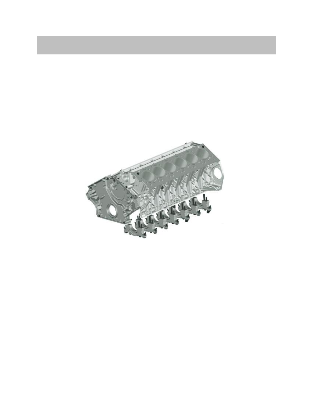
Engine Block
The engine block of the N74 engine is a new design. It is similar to the N63 engine
concept, but with a cylinder bank angle of 60° and the following features:
• Block made of an aluminum alloy (Alusil)
• Closed deck crankcase design
• Honed cylinder liners
• Lowered side walls (deep skirt) with main bearing caps
• Double main bearing bolting with additional side wall connection.
The closed-deck design and the bolt connections of the cylinder heads in the bottom of
the cylinder housing ensure high rigidity and low deformation of the exposure-honed
cylinder liners.
The crankcase with lowered side walls (deep skirt) has double main bearing bolting
with additional side wall connections by means of threaded support sleeves and bolts
designed to absorb the lateral forces from the crankshaft common on the V-engine configuration.
There are coolant passages to cool the (hot zone) area between the cylinders. In order
to keep the pumping losses in the crankcase to a minimum, there are one to six ventilation holes below each of the main bearing seats.
The use of separate channels for the oil return from the cylinder heads and for crankcase
ventilation reduces the amount of oil in the blow-by gases.
As on the N63 engine, the torque converter is bolted onto the flywheel through an
opening in the converter housing with six bolts positioned at an angle of 30°. This
makes it easier to replace the transmission.
14
N74 Engine

Cylinder Head
The cylinder head features the injector and spark plugs arranged in the center of the
combustion chamber. The layout of the high pressure fuel pumps is similar to that on the
N63 engine; however because of the conventional cylinder head arrangement (intake side
on the inside, exhaust side on the outside) they are located above the intake camshafts
(respectively between cylinders 1 and 2 and 7 and 8).
As on the N63 engine, the intake port features a trailing edge (around the valve seats) for
creating more intensive charge movement.
Coolant flows diagonally across the cylinder head (from the outer side of the engine
towards the V chamber), whereby the inlet is at the outside rear and the outlet at the
inside front. This is referred to as diagonal cooling.
As on the N63 engine, only one non-return valve for the oil circuit is incorporated into
the cylinder head. The N74 uses two VANOS non-return valves, they are now integrated
into the VANOS solenoid valves.
Cylinder Head Cover
The cylinder head covers are made of die-cast aluminum. They accommodate the oil
separation of the crankcase ventilation. The oil separators are made of plastic and are
very similar to those in the N63 engine.
Oil Sump
The engine oil sump is structured in two parts. The upper and lower sections of the diecast aluminum oil sump have been optimized with regard to strength and acoustics.
A two-part oil deflector also ensures particularly low oil foaming in extreme driving situations. A surge plate ensures that an adequate oil level is achieved in the case of high
longitudinal and lateral dynamic forces.
The thermostat for the engine oil cooler as well as the oil filter with an oil filter insert made
of synthetic fleece are integrated in the engine oil sump. The lower section of the oil
sump contains the oil level sensor that enables electronic oil level measurement. There is
no oil dipstick.
15
N74 Engine

Crankcase Ventilation
Crankcase ventilation works to a large extent in the same way as on the N63 engine.
However, the N74 has register ventilation, which is also used on the S63 engine.
16
N74 Engine
 Loading...