


Technical�training.
Product�information.
N63TU2�Engine
BMW�Service

General�information
Symbols�used
The�following�symbol�is�used�in�this�document�to�facilitate�better�comprehension�or�to�draw�attention
to�very�important�information:
Contains�important�safety�information�and�information�that�needs�to�be�observed�strictly�in�order�to
guarantee�the�smooth�operation�of�the�system.
Information�status�and�national-market�versions
BMW�Group�vehicles�meet�the�requirements�of�the�highest�safety�and�quality�standards.�Changes
in�requirements�for�environmental�protection,�customer�benefits�and�design�render�necessary
continuous�development�of�systems�and�components.�Consequently,�there�may�be�discrepancies
between�the�contents�of�this�document�and�the�vehicles�available�in�the�training�course.
This�document�basically�relates�to�the�European�version�of�left-hand�drive�vehicles.�Some�operating
elements�or�components�are�arranged�differently�in�right-hand�drive�vehicles�than�shown�in�the
graphics�in�this�document.�Further�differences�may�arise�as�the�result�of�the�equipment�specification�in
specific�markets�or�countries.
Additional�sources�of�information
Further�information�on�the�individual�topics�can�be�found�in�the�following:
• Owner's�Handbook
• Integrated�Service�Technical�Application.
Contact:�conceptinfo@bmw.de
©2015�BMW�AG,�Munich
Reprints�of�this�publication�or�its�parts�require�the�written�approval�of�BMW�AG,�Munich.
The�information�contained�in�this�document�forms�an�integral�part�of�the�technical�training�of�the
BMW�Group�and�is�intended�for�the�trainer�and�participants�in�the�seminar.�Refer�to�the�latest�relevant
information�systems�of�the�BMW�Group�for�any�changes/additions�to�the�technical�data.
Contact:
Achim�Gloede
Tel.:�+49�(0)�89�382�50398
E-mail:�achim.gloede@bmw.de
Information�status:�May�2015
BV-72/Technical�Training

N63TU2�Engine
Contents
1. Introduction.............................................................................................................................................................................................................................................1
1.1. Models.....................................................................................................................................................................................................................................1
1.2. Technical�data............................................................................................................................................................................................................. 1
1.2.1. Full�load� diagram�................................................................................................................................................................ 3
1.3. New�features�on�the�N63TU2�engine...................................................................................................................................4
1.3.1. Overview............................................................................................................................................................................................. 4
1.3.2. N63TU2�engine�components........................................................................................................................... 5
1.4. Engine�identification..................................................................................................................................................................................... 11
1.4.1. Engine�designation....................................................................................................................................................... 11
1.4.2. Engine�identification....................................................................................................................................................11
2. Engine�Mechanical................................................................................................................................................................................................................ 13
2.1. Engine�housing..................................................................................................................................................................................................... 13
2.1.1. Crankcase.....................................................................................................................................................................................13
2.1.2. Cylinder�head�gasket................................................................................................................................................. 15
2.1.3. Cylinder�head......................................................................................................................................................................... 16
2.1.4. Cylinder�head�cover.....................................................................................................................................................18
2.1.5. Oil�sump......................................................................................................................................................................................... 25
2.2. Crankshaft�drive...................................................................................................................................................................................................27
2.2.1. Crankshaft�with�bearings.....................................................................................................................................28
2.2.2. Flywheel.......................................................................................................................................................................................... 29
2.2.3. Connecting�rod�with�bearing.........................................................................................................................30
2.2.4. Piston�with�piston�rings......................................................................................................................................... 32
2.3. Camshaft�drive/chain�drive................................................................................................................................................................. 34
2.4. Valve�gear.......................................................................................................................................................................................................................35
2.4.1. Design................................................................................................................................................................................................ 35
2.4.2. Valvetronic................................................................................................................................................................................... 39
2.5. Belt�drive......................................................................................................................................................................................................................... 50
2.6. SynTAK�(synergy�thermo-acoustic�capsule)......................................................................................................... 51
3. Oil�Supply...............................................................................................................................................................................................................................................52
3.1. Overview.......................................................................................................................................................................................................................... 52
3.1.1. Hydraulic�circuit�diagram..................................................................................................................................... 52
3.2. Oil�pump�and�pressure�control.................................................................................................................................................... 54
3.2.1. Intake�neck................................................................................................................................................................................. 54
3.2.2. Oil�pump.........................................................................................................................................................................................55
3.2.3. Map�control�valve.............................................................................................................................................................57
3.2.4. Normal�operation..............................................................................................................................................................59
3.2.5. Emergency�operation................................................................................................................................................60
3.3. Oil�cooling�and�filtering............................................................................................................................................................................ 62
3.3.1. Oil�cooling....................................................................................................................................................................................63

N63TU2�Engine
Contents
3.3.2. Oil�filtering................................................................................................................................................................................... 65
3.4. Oil�monitoring..........................................................................................................................................................................................................65
3.4.1. Oil�level.............................................................................................................................................................................................65
3.4.2. Oil�pressure�sensor...................................................................................................................................................... 65
3.4.3. Oil�temperature�sensor........................................................................................................................................... 66
3.5. Oil�spray�nozzles................................................................................................................................................................................................. 66
3.5.1. Piston�crown�cooling..................................................................................................................................................66
3.5.2. Chain�drive..................................................................................................................................................................................67
3.5.3. Camshaft........................................................................................................................................................................................68
3.5.4. Valvetronic�servomotor........................................................................................................................................... 68
4. Cooling.........................................................................................................................................................................................................................................................69
4.1. System�overview.................................................................................................................................................................................................70
4.1.1. Cooling�circuit,�engine�...........................................................................................................................................71
4.1.2. Cooling�circuit�of�charge�air�cooler�and�DME..................................................................... 83
4.2. Heat�management........................................................................................................................................................................................... 86
4.2.1. Auxiliary�water�pump.................................................................................................................................................. 86
4.2.2. Data-map�thermostat................................................................................................................................................ 87
4.2.3. Coolant�temperature�sensor.......................................................................................................................... 96
5. Intake�Air�and�Emission�System................................................................................................................................................................. 97
5.1. Overview.......................................................................................................................................................................................................................... 97
5.2. Intake�air�system.................................................................................................................................................................................................99
5.2.1. Hot�film�air�mass�meter..................................................................................................................................... 100
5.2.2. Intake�silencer...................................................................................................................................................................101
5.2.3. Intake�manifold................................................................................................................................................................ 101
5.3. Exhaust�turbocharger............................................................................................................................................................................. 102
5.3.1. Charging�pressure�control.............................................................................................................................103
5.3.2. Function......................................................................................................................................................................................104
5.4. Exhaust�emission�system................................................................................................................................................................ 105
5.4.1. Exhaust�manifold..........................................................................................................................................................105
5.4.2. Catalytic�converter.....................................................................................................................................................106
5.4.3. Exhaust�system...............................................................................................................................................................108
5.4.4. Electrically�controlled�exhaust�flaps...............................................................................................110
6. Vacuum�System......................................................................................................................................................................................................................112
7. Fuel�Preparation.................................................................................................................................................................................................................... 113
7.1. Overview......................................................................................................................................................................................................................113
7.2. Fuel�pump� control........................................................................................................................................................................................114
7.3. High�pressure�pump.................................................................................................................................................................................114

N63TU2�Engine
Contents
7.4. Injectors........................................................................................................................................................................................................................ 115
8. Fuel�Supply.....................................................................................................................................................................................................................................116
9. Engine�Electrical�System..................................................................................................................................................................................... 117
9.1. Overview......................................................................................................................................................................................................................117
9.2. Engine�control�unit..................................................................................................................................................................................... 124
9.2.1. Overall�function............................................................................................................................................................... 126
9.3. Alternator....................................................................................................................................................................................................................127


N63TU2�Engine
1.�Introduction
The�N63TU2�engine�replaces�the�predecessor�N63TU.�The�key�enhancements�of�the�N63TU2�over
the�N63TU�are�the�improved�exhaust-gas�characteristics,�the�availability�of�the�engine�torque�over�a
wider�speed�range�together�with�optimized�consumption,�and�a�more�efficient�production�process�in
the�plant�for�the�new�N63TU2�engine.
The�unique�selling�points�of�the�new�N63TU2�engine�for�the�market�include�innovative�detailed
solutions�such�as�the�internal�engine�thermal�management�system�during�warm-up�(called�SCC,
"Split�Cooling�Combined",�the�engine�oil/coolant�heat�exchanger�integrated�into�the�engine�V,
the�half-shell�intake�system�and�the�engine�charging�using�the�twin-scroll�exhaust�turbocharger
technology.
The�new�N63TU2�engine�will�be�introduced�into�series�production�for�the�first�time�with�the�new�G12.
In�this�documentation�the�differences�to�the�N63TU�predecessor�engine�are�described.
1.1.�Models
Development�series N63B44O2�engine Series�introduction
G12 BMW�750i
BMW�750i�xDrive
07/2015
1.2.�Technical�data
Engine Unit N63B44O1 N63B44O2
Development�series F02�LCI G12
Model�designation BMW�750i BMW�750i
Design V8 V8
Displacement [cm³] 4395 4395
Firing�order 1-5-4-8-6-3-7-2 1-5-4-8-6-3-7-2
Bore/stroke [mm] 89/88.3 89/88.3
Power�output
at�engine�speed
Cutoff�speed [rpm] 6,500 6,500
Power�output�per�liter [kW/l] 75/1 75/1
Torque
at�engine�speed
[kW�(HP)]
[rpm]
[Nm�(lb-ft)]
[rpm]
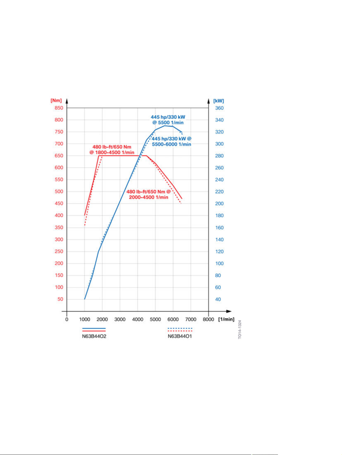
330�(445)
5,500�-�6,000
650�(480)
2,000�-�4,500
330�(445)
5,500�-�6,000
650�(480)
1,800�-�4,500
Compression�ratio [ε] 10.0 10.5
Valves�per�cylinder 4 4
Fuel [RON] 91�-�98 91�-�98
Fuel�consumption�complying�with�EU [l/100km] 8.6 -
CO2�emissions [grams�per
kilometer]
199 -
1

N63TU2�Engine
1.�Introduction
Engine Unit N63B44O1 N63B44O2
Digital�Motor�Electronics MEVD�17.2.8 DME�8.8
Exhaust�emissions�legislation ULEV�II ULEV�II
Maximum�speed [km/h] 250 250
Acceleration�0–100�(0–62)km/h�(mph) [s] 4.8 -
The�data�on�consumption/acceleration�and�CO2�emissions�for�this�model�was�unavailable�at�the�time
this�document�was�created.
2
N63TU2�Engine
1.�Introduction
1.2.1.�Full�load�diagram
N63TU�engine�in�the�F01�LCI/N63TU2�engine�in�the�G12
Full�load�diagram,�N63B44O2�engine�compared�to�the�N63B44O1�engine
3

N63TU2�Engine
1.�Introduction
1.3.�New�features�on�the�N63TU2�engine
1.3.1.�Overview
N63TU2�engine,�exploded�diagram
4

N63TU2�Engine
1.�Introduction
Index Explanation
1 Cylinder�head�cover
2 Cylinder�head�cover�gasket
3 Cylinder�head
4 Cylinder�head�gasket
5 Crankcase
6 Crankshaft�drive
7 Oil�sump�gasket,�top
8 Oil�sump,�top
9 Oil�sump�gasket,�bottom
10 Oil�sump,�bottom
11 Timing�case�cover�gasket
12 Timing�case�cover
1.3.2.�N63TU2�engine�components
Engine�mechanics
Component New
feature
Cylinder�head
cover
Cylinder�head
Cylinder�head
gasket
Identical
concept
Carry-over
part
Comment
Modified�to�accommodate�VANOS
solenoid�valves.
Partial�integration�of�the�intake
neck�into�the�cylinder�head.
Optimized�weight�–�weight
saving�of�1.5�kg�per�cylinder�head
compared�to�the�N63TU�engine.
Mountings�for�VANOS�solenoid
valves�removed
Ducts�for�directing�the�engine�oil
simplified.
Internal�engine�thermal
management�system�integrated.
Revised�cylinder�head�gasket�at
water�passages�for�the�thermal
management�system.
Changeover�to�partial�screen
printing�coating.
Crankcase
Internal�engine�thermal
management�system�integrated.
Modified�to�accommodate�the
engine�oil/coolant�heat�exchanger.
Ducts�for�directing�the�engine�oil
simplified.
5

N63TU2�Engine
1.�Introduction
Component New
feature
Crankshaft
with�main
bearing
Connecting
rod
Gudgeon�pin Taken�over�from�N63TU�engine.
Connecting
rod�bearing
shells
Piston
Piston�rings
Flywheel
SynTAK
Identical
concept
Carry-over
part
Comment
Taken�over�from�N63TU�engine.
Taken�over�from�N63TU�engine.
Material�changed�over�to�steel/
aluminium�anti-friction�coating
(IROX).
Oil�scraper�ring�groove�modified
from�4�to�8�oil�drains.
Modified�to�accommodate�a
higher�compression�ratio.
Taken�over�from�N63TU�engine.
Width�of�oil�scraper�ring.
reduced�from�2�mm�to�1.8�mm.
Three-part�flywheel�(four-part�on
the�N63TU).
0.52�kg�weight�reduction�.
Synergy�thermoacoustic�capsule.
Provides�acoustic�and�thermal
insulation.
Valve�gear
Component New
feature
Chain�drive
with�timing
chain
VANOS
Fully�variable
valve�lift
adjustment
Identical
concept
Carry-over
part
Comment
Taken�over�from�N63TU�engine.
Taken�over�from�modular�engines.
Increased�adjustment�speed�and
reduced�susceptibility�to�dirt.
Taken�over�from�N63TU�engine.
Gate�only�screwed�using�one
screw,�as�on�modular�engines.
6

N63TU2�Engine
1.�Introduction
Component New
feature
Intake�valves
and�exhaust
valves
Valve�guides
Camshafts
Belt�drive�and�ancillary�components
Component New
feature
Vibration
damper
Belt�drive
Identical
concept
Identical
concept
Carry-over
part
Carry-over
part
Comment
Chrome-plated�valve�stems.
Material�changed�over�to�hightemperature-resistant�brass.
Modified�mountings�to
accommodate�VANOS�units�from
modular�engines.
Exhaust�camshaft�with�modified
timing.
Comment
Optimized�weight�(500�g�lighter
than�on�the�N63TU).
Concept�taken�over�from�the
N63TU�engine.
Belt�pulley�for�crankshaft�is�new
and�made�from�high-strength
plastic.
Belt�level�moved�forwards
by�20�mm.
Air�conditioning�compressor
arranged�on�the�right�of�the
engine.
7

N63TU2�Engine
1.�Introduction
Oil�supply
Component New
feature
Oil�pump
Oil�sump
Oil�filter
module
Oil�spray
nozzles
Air�intake�and�exhaust�emission�systems
Component New
Intake�manifold Half-shell�intake�system�used.
feature
Identical
concept
Identical
concept
Carry-over
part
Carry-over
part
Comment
Characteristic�map-controlled
pendulum�slide�pump.
Two�versions�for�rear-wheel�drive
and�four-wheel�drive.
Four-wheel�drive�with�aperture�for
front-wheel�drive.
Rear-wheel�drive�with�sealed
side�boxes�for�optimal�use�of�the
available�space.
Oil�pressure�sensor�and
characteristic�map�control�valve
integrated.
Modified�opening�pressure�and
closing�pressure.
Comment
Exhaust
manifold
Exhaust
turbocharger
Exhaust
system
Heat
shields
Upstream
catalytic
converter
Vacuum�system
Component New
Vacuum
pump
feature
Identical
concept
Carry-over
part
Adapted�to�the�twin-scroll
turbocharger�concept.
Twin-scroll�concept.
Electrical�wastegate�valves.
Optimized�for�minimal�exhaust�gas
pressure.
Electrical�exhaust�flaps.
Active�Sound�Design�(ASD)�in�the
passenger�compartment.
Taken�over�from�N63TU�engine.
Top�heat�shield�adapted�to�twinscroll�concept.
Comment
Taken�over�from�N63TU�engine.
Auxiliary�consumers�removed.
8

N63TU2�Engine
1.�Introduction
Fuel�preparation
Component New
feature
High�pressure
pump
Injectors Taken�over�from�N63TU�engine.
Cooling
Component New
feature
Engine�oil-tocoolant�heat
exchanger
Hightemperature
circuit
Engine�cooling
Mechanical
coolant
pump
Characteristic
map
thermostat
Identical
concept
Identical
concept
Carry-over
part
Carry-over
part
Comment
Bank-specific�with�modified�inlet
connector.
Comment
Engine�oil/air�heat�exchanger
removed�from�front�of�vehicle,
replaced�by�engine�oil/coolant
heat�exchanger�in�engine�V.
Additional�electric�coolant�pump
for�exhaust�turbocharger.
Further�developed�into�a
characteristic�map-dependent
coolant�pump.
With�opening�detection�and�return
passages�barrier.
Lowtemperature
circuit
Charge�air
cooling
Engine�electrical�system
Component New
feature
Digital�Motor
Electronics
DME
VANOS
solenoid�valves
Valvetronic
servomotor
Hot�film�air
mass�meter
Indirect�charge�air�cooling�with�2
heat�exchangers.
Identical
concept
Carry-over
part
Own�coolant�circuit.
Electric�coolant�pump.
Comment
DME�8.8.0
Hardware�from�modular�engines.
Coolant�cooling.
Taken�over�from�modular�engines.
Taken�over�from�modular�engines.
Hot�film�air�mass�meter�8�taken
over�from�modular�engines.
9

N63TU2�Engine
1.�Introduction
Component New
feature
Oxygen
sensors
Ignition�coils
Spark�plugs Taken�over�from�N63TU�engine.
Knock�sensors Taken�over�from�N63TU�engine.
Oil
temperature
sensor
Intake�pipe
pressure/
temperature
sensor
Camshaft/
crankshaft
sensor
Coolant
temperature
sensor
Identical
concept
Carry-over
part
Comment
Control�sensor�taken�over�from
the�N63TU�engine�(LSU�ADV).
Monitoring�sensor�taken�over�from
modular�engines�(LSF�Xfour).
Extended�ignition�coils�based�on
the�N55�engine.
Taken�over�from�N63TU�engine.
Taken�over�from�N63TU�engine.
Taken�over�from�modular�engines.
Can�be�recorded�as�a�camshaft
sensor�or�crankshaft�sensor.
Taken�over�from�the�N55�engine.
Oil�pressure
sensor
Oil�level�sensor
Rail�pressure
sensor
Electrical
wastegate
valve�actuator
Starter�motor Adapted�to�MSA�2.3.
Alternator Taken�over�from�modular�engines.
Electromotive
throttle
controller
Oil�pressure�sensor�instead�of�oil
pressure�switch�in�the�N63TU.
Oil-level�sensor�based�on�oil-level
sensor�in�the�N63TU.
Taken�over�from�the�N63TU
engine.
Taken�over�from�the�N55�engine.
Taken�over�from�modular�engines.
10

N63TU2�Engine
1.�Introduction
1.4.�Engine�identification
1.4.1.�Engine�designation
The�N63TU2�engine�in�version�N63B44O2�is�described�in�this�documentation.�The�N63B40O2
engine�in�a�different�capacity�class�is�also�available�for�the�Chinese�market;�however,�this�engine�is�not
considered�in�this�documentation.�The�basic�design�of�the�N63B40O2�engine�is�identical�to�that�of�the
N63B44O2�engine.�The�reduced�capacity�is�the�result�of�a�reduced�piston�stroke�caused�by�a�longer
connecting�rod�and�the�reduced�compression�ratio.
In�the�technical�documentation,�the�engine�designation�is�used�to�ensure�unambiguous�identification
of�the�engine.
The�technical�documentation�also�contains�the�short�form�of�the�engine�designation�N63TU2,�which
only�indicates�the�engine�type.
Itemization
Index Explanation
N BMW�Group�"New�Generation"
6 V8�engine
3 Engine�with�exhaust�turbocharger,�Valvetronic
and�direct�fuel�injection�(TVDI)
B Gasoline�engine�installed�longitudinally
44 4.4�liters�displacement
O Upper�performance�class
2 Second�revision
1.4.2.�Engine�identification
The�engines�have�an�identification�mark�on�the�crankcase�to�ensure�unambiguous�identification�and
classification.�This�engine�identification�is�necessary�for�approval�by�government�authorities.�The�first
six�positions�of�the�engine�identification�correspond�to�the�engine�designation.
The�engine�number�can�be�found�on�the�engine�above�the�engine�identification.�This�consecutive
number,�in�conjunction�with�the�engine�identification,�permits�unambiguous�identification�of�each
individual�engine.
11

N63TU2�Engine
1.�Introduction
Example�of�an�N63TU�engine,�engine�identification�and�engine�number
Index Explanation
22620097 Individual,�consecutive�engine�number
N BMW�Group�"New�Generation"
6 V8�engine
3 Engine�with�exhaust�turbocharger,�Valvetronic�and�direct�fuel�injection�(TVDI)
B Gasoline�engine�installed�longitudinally
44 4.4�liters�displacement
B Type�test�concerns,�standard
12
N63TU2�Engine
2.�Engine�Mechanical
2.1.�Engine�housing
The�engine�housing�comprises�of�the�engine�block,�cylinder�heads,�cylinder�head�covers,�oil�sump�and
the�gaskets.
2.1.1.�Crankcase
The�crankcase�on�the�N63TU2�engine�has�been�completely�redesigned�and�is�manufactured�from
low-pressure�die�cast�AlSi17Cu4Mg,�as�on�the�N63TU�engine.�The�cylinder�barrels�are�made�from
Alusil.�Like�its�predecessor�in�the�N63TU�engine,�the�closed-deck�crankcase�in�the�N63TU2�engine�is
characterized�by�a�double�main�bearing�screw�connection�with�side�wall�connection.
The�crankcase�cast�part�consists�of�the�cylinder�bores�with�Alusil�coating,�the�bearing�ways�with�the
bore�holes�for�the�crankshaft�and�associated�bearings�and�the�water�jackets�of�the�cylinders.�The
water�jackets�of�the�crankcase�and�the�water�ducts�in�the�cylinder�head�form�the�basis�for�the�revised
coolant�passages�inside�the�engine�and�the�thermal�management�system�of�the�N63TU2�engine.�This
design�has�also�deleted�the�need�for�the�coolant�chamber�sealing�cap�at�the�rear�on�the�crankcase.
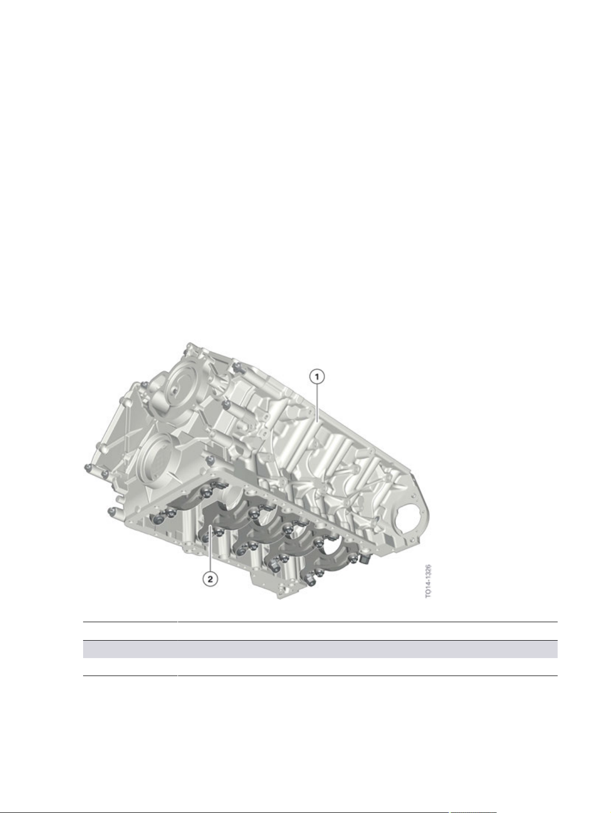
N63TU2�engine,�crankcase�with�screw�connections
Index Explanation
1 Crankcase
2 Double�main�bearing�screw�connection�with�side�wall�connection
The�V�area�of�the�N63TU2�has�been�adapted�to�the�crankcase�with�regard�to�the�attachment�of�the
engine�oil/coolant�heat�exchanger.�The�oil�holes�as�well�as�the�water�ducts�in�the�crankcase�have�been
adapted�to�the�connection�required�for�the�engine�oil/coolant�heat�exchanger.
13
N63TU2�Engine
2.�Engine�Mechanical
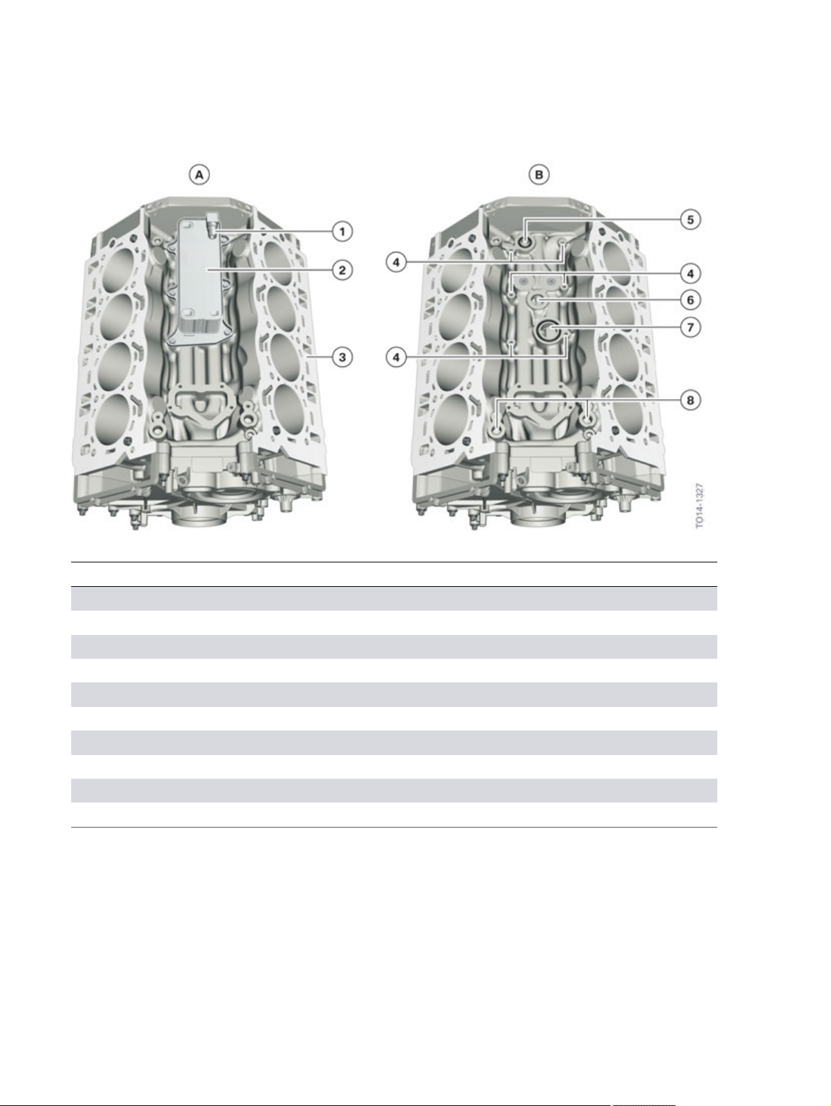
N63TU2�engine,�crankcase
Index Explanation
A Crankcase�with�engine�oil/coolant�heat�exchanger
B Crankcase�without�engine�oil/coolant�heat�exchanger
1 Coolant�return�from�engine�oil/coolant�heat�exchanger
2 Engine�oil-to-coolant�heat�exchanger
3 Crankcase
4 6x�screw�connection�for�the�engine�oil/coolant�heat�exchanger
5 Oil�return�from�engine�oil/coolant�heat�exchanger
6 Oil�supply�to�engine�oil/coolant�heat�exchanger
7 Coolant�supply�to�engine�oil/coolant�heat�exchanger
8 Oil�supply�for�exhaust�turbocharger
14

N63TU2�Engine
2.�Engine�Mechanical
2.1.2.�Cylinder�head�gasket
As�on�the�N63TU�engine,�a�three-layer�spring�steel�gasket�is�used�for�the�cylinder�head�gasket.�There
is�a�stopper�plate�(2)�in�the�area�of�the�cylinder�bores�in�order�to�achieve�sufficient�contact�pressure�for
sealing.
N63TU2�engine,�cylinder�head�gasket
Index Explanation
1 Top�spring�steel�layer�with�anti-stick�coating
2 Stopper�layer
3 Bottom�spring�steel�layer�with�anti-stick�coating
In�contrast�to�the�N63TU�engine,�on�the�N63TU2�the�contact�surfaces�with�the�cylinder�head�and
engine�block�are�no�longer�fully�coated,�but�instead�have�partial�screen�printing�coating.�By�omitting
the�coating�in�the�coolant�duct�areas,�the�risk�of�the�coating�coming�loose�and�contaminating�the
coolant�circuit�is�minimized.
N63TU2�engine,�cylinder�head�gasket�coating
Index Explanation
1 Partial�screen�printing�coating
2 Cylinder�head�gasket
15

N63TU2�Engine
2.�Engine�Mechanical
2.1.3.�Cylinder�head
The�cylinder�head�of�the�N63TU2�engine�is�a�new�feature�with�partially�integrated�intake�system.
Thanks�to�this�partially�integrated�intake�system�in�the�cylinder�head,�the�passages�characteristics
of�the�incoming�air�has�been�optimized�and�the�space�required�to�install�the�intake�pipe�has�been
significantly�reduced.�It�has�also�allowed�the�weight�of�the�cylinder�head�to�be�reduced�by�1.5�kg�/�3.3
lbs.
N63TU2�engine,�cylinder�head
Index Explanation
1 Sealing�flange�for�intake�system
2 Partially�integrated�intake�pipe
3 Flange�for�Valvetronic�servomotor
4 Cylinder�head�bank�1
With�the�exception�of�the�combustion�chamber�dome�and�the�valve�gear�(which�have�been�taken
over�from�the�N63TU),�the�cylinder�head�is�a�completely�new�component�in�the�N63TU2�engine.�The
coolant�passages�in�the�cylinder�head�are�separate�from�the�coolant�passages�around�the�cylinder
bores.�By�taking�over�the�VANOS�solenoid�valves�into�the�cylinder�head�cover�and�the�VANOS
adjusters�(as�is�already�the�case�for�the�N20�engine�and�the�modular�engines),�the�bore�holes�for�the
VANOS�solenoid�valves�in�the�cylinder�head�could�be�removed,�meaning�the�associated�engine�oil
ducts�in�the�cylinder�head�can�also�be�simplified.
3rd-generation�Valvetronic�technology�is�also�used�in�the�N63TU2�engine,�as�is�already�the�case�in�the
N55�and�N63TU�engines.�The�Valvetronic�servomotor�is�connected�on�the�outer�side�at�the�cylinder
head.
The�combination�of�exhaust�turbocharger,�Valvetronic�and�direct�fuel�injection�is�known�as�Turbo
Valvetronic�Direct�Injection�(TVDI).
16
N63TU2�Engine
2.�Engine�Mechanical
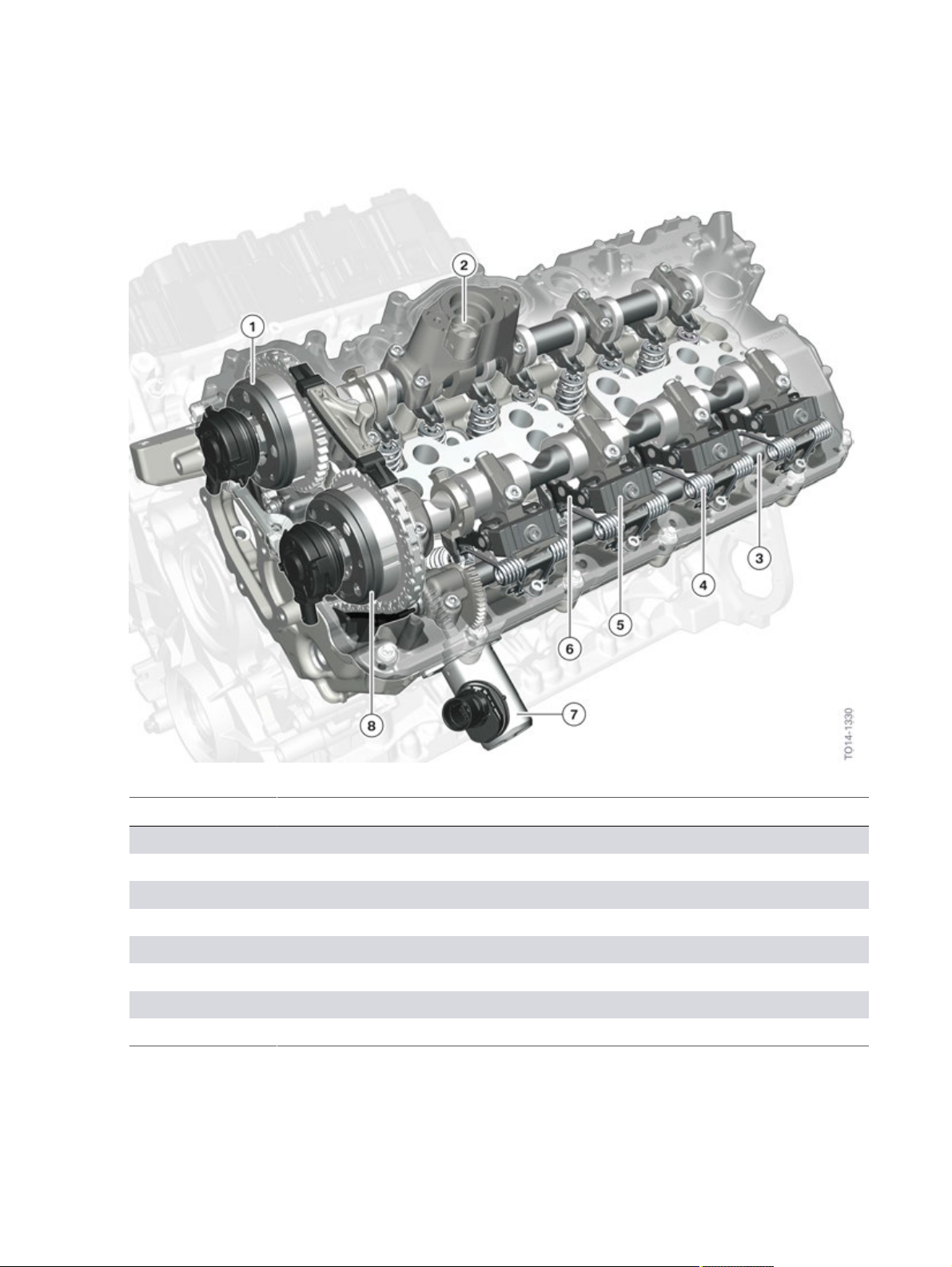
N63TU2�engine,�cylinder�head�with�Valvetronic
Index Explanation
1 VANOS,�exhaust�side
2 Roller�tappet,�high-pressure�pump
3 Eccentric�shaft
4 Torsion�spring
5 Gate/guide�block
6 Intermediate�lever
7 Valvetronic�servomotor
8 VANOS,�intake�side
17
N63TU2�Engine
2.�Engine�Mechanical
2.1.4.�Cylinder�head�cover
Design
The�design�of�the�cylinder�head�cover�in�the�N63TU2�engine�is�the�same�as�for�the�N63TU�engine,
but�with�minor�modifications�to�the�crankcase�ventilation�and�the�mountings�for�the�VANOS�solenoid
valves.�As�in�the�N63TU,�a�ventilation�register�with�an�additional�ventilation�line�is�used.�Each�bank�has
its�own�oil�separator.�An�additional�line�from�the�crankcase�ventilation�to�the�air�intake�system�is�not
used�as�corresponding�bore�holes�for�the�individual�intake�ports�are�integrated�in�the�cylinder�head.
The�camshaft�sensors�are�positioned�on�the�front�of�the�cylinder�head�cover.
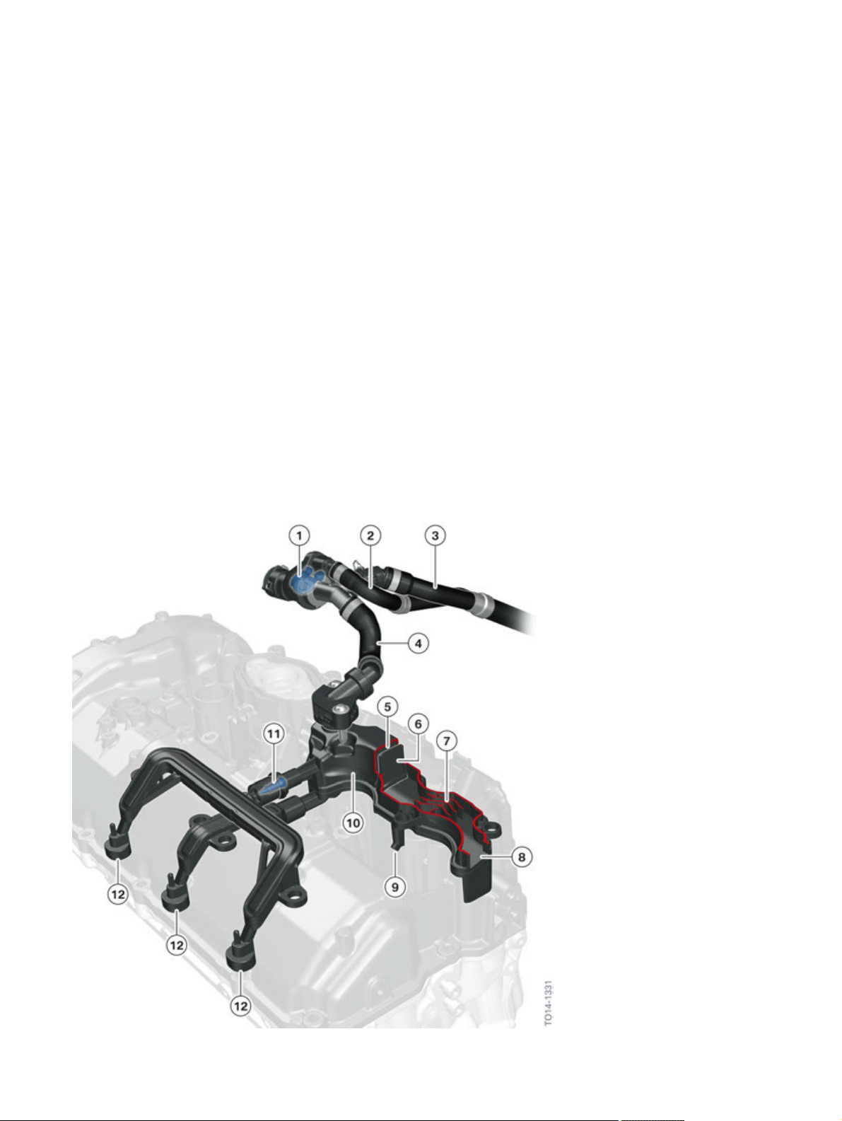
To�separate�the�oil�contained�in�the�blow-by�gas,�a�labyrinth�oil�separator�is�used.�A�pre-separator
(7)�and�a�fine�deflection�plate�with�small�air�vents�(6)�are�in�the�passages�direction.�The�oil�drops�are
separated�at�these�barriers�and�return�to�the�cylinder�head�via�the�return�line�(9�and�10).�An�impact
surface�(5)�with�an�upstream�mesh�that�ensures�further�separation�of�oil�particles.�The�oil�return
(10)�is�equipped�with�a�non-return�valve�in�order�to�prevent�direct�intake�of�blow-by�gasses�without
separation.�If�the�oil�level�increases�in�this�pipe,�the�non-return�valve�opens�and�the�oil�drops�into�the
cylinder�head.�Finally,�depending�on�the�operating�condition�of�the�engine,�the�cleaned�blow-by�gases
are�fed�back�into�the�intake�system�either�via�the�non-return�valve�(1)�or�via�the�volume�control�valve
(12�and�3).
N63TU2�engine,�cylinder�head�cover�with�crankcase�ventilation
18

N63TU2�Engine
2.�Engine�Mechanical
Index Explanation
1 Non-return�valve�for�the�clean�air�pipe�with�leak�hole
2 Purge�air�line
3 Intake�pipe�with�volume�control�valve
4 Line�to�clean�air�pipe
5 Impact�surface�with�upstream�mesh�that
6 Fine�deflector�plate�with�small�air�vents
7 Pre-separator
8 Inlet�for�blow-by�gases
9 Oil�return
10 Oil�separator
11 Volume�control�valve�for�the�air�intake�system�with�throttle�function
12 Connecting�line�via�blow-by-gas�channel�for�the�intake�port
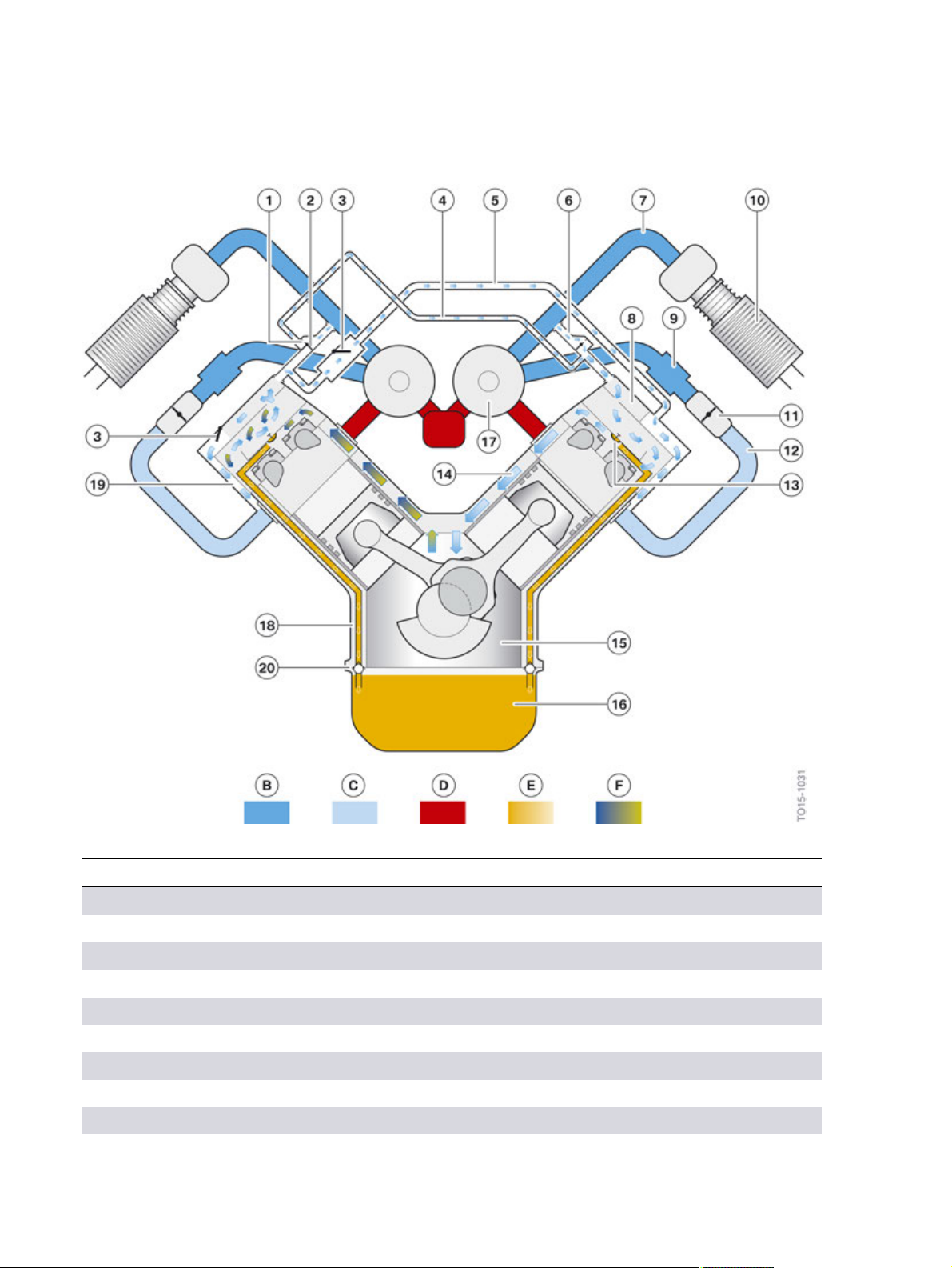
Crankcase�ventilation�in�naturally�aspirated�engine�operation
In�the�naturally�aspirated�engine�operation�there�is�a�vacuum�in�the�air�intake�system�(12).�The�two
volume�control�valves�(3)�are�opened.�The�cleaned�blow-by�gases�reach�the�inlet�areas�of�both�banks
and�thus�the�air�intake�system�through�the�left�oil�separator�via�the�intake�pipe�(5)�and�ducts�in�the
cylinder�head�(19).�As�there�is�a�risk�that�oil�may�be�drawn�in�via�the�crankcase�ventilation�in�the�case�of
large�vacuums,�the�volume�control�valve�has�a�throttle�function�and�limits�the�passages�and�thus�also
the�pressure�level�in�the�crankcase.
The�vacuum�in�the�crankcase�ventilation�keeps�the�non-return�valves�(2�and�6)�closed.�Fresh�air
flows�from�the�two�clean�air�pipes�through�the�right�oil�separator�into�the�inside�of�the�engine�via�the
overlying�leakage�holes.�The�vacuum�in�the�crankcase�ventilation�is�thus�restricted.�At�the�same�time
the�chemical�ageing�of�the�lubricating�oil�and�also�the�water�content�in�the�blow-by�gases�are�reduced
by�flushing�the�crankcase�with�fresh�air.
19
N63TU2�Engine
2.�Engine�Mechanical
N63TU2�engine,�overview�of�crankcase�ventilation�in�the�naturally�aspirated�engine�operation
Index Explanation
B Ambient�pressure
C Vacuum
D Exhaust�gas
E Oil
F Blow-by�gases
1 Leakage�hole�in�the�housing�of�the�non-return�valve
2 Non-return�valve�for�the�clean�air�pipe
3 Volume�control�valve�for�the�air�intake�system�with�throttle�function
4 Purge�air�line
5 Intake�system�from�bank�2�to�bank�1
20
N63TU2�Engine
2.�Engine�Mechanical
Index Explanation
6 Line�to�the�clean�air�pipe�with�non-return�valve�and�leakage�hole
7 Clean�air�pipe
8 Oil�separator
9 Charge�air�cooler
10 Intake�silencer�with�hot�film�air�mass�meter�8
11 Throttle�valve
12 Intake�manifold
13 Oil�return
14 Ventilation�duct
15 Crank�chamber
16 Oil�sump
17 Exhaust�turbocharger
18 Oil�return�duct
19 Duct�in�the�cylinder�head
20 Non-return�valve
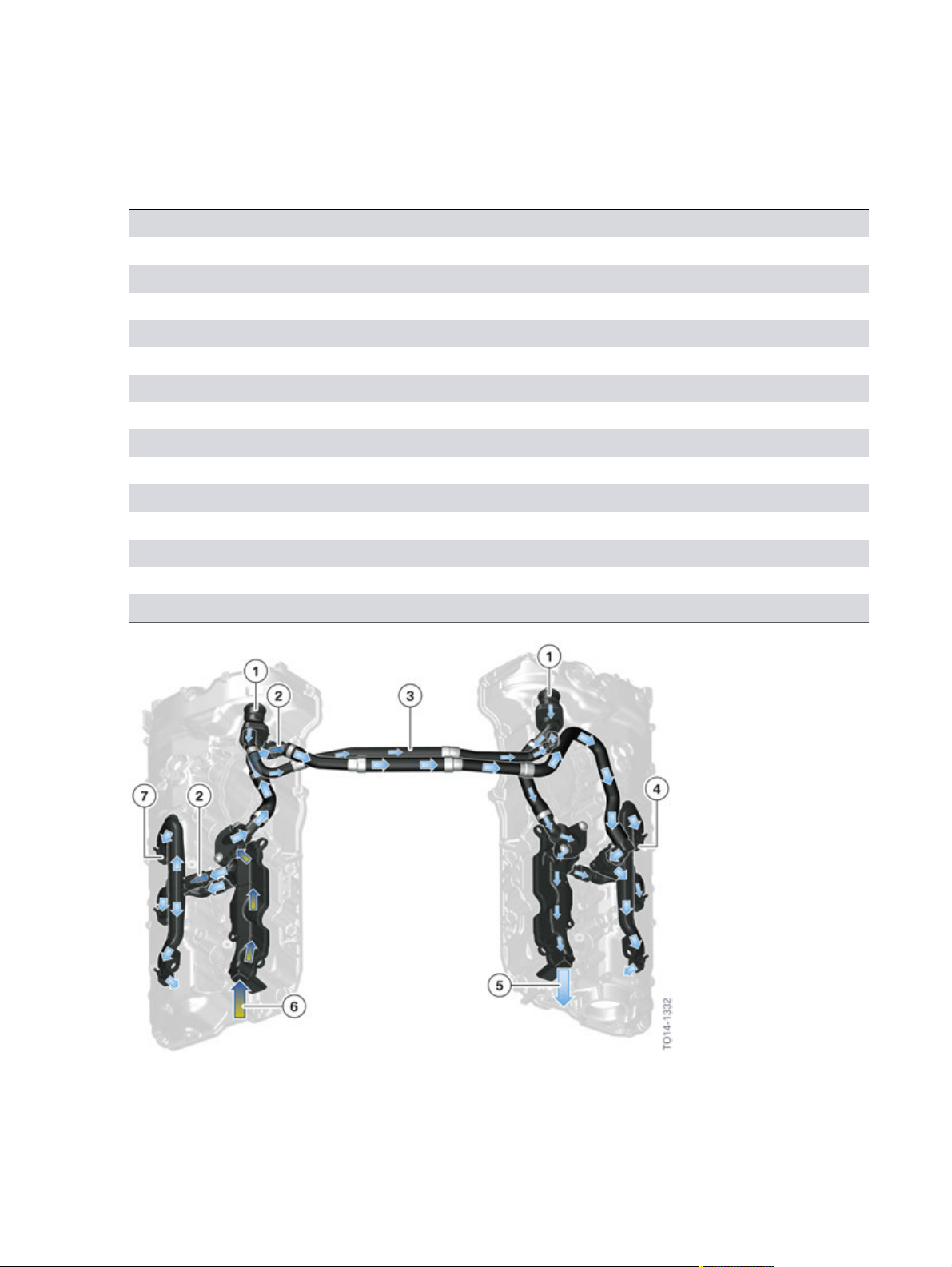
N63TU2�engine,�components�of�the�crankcase�ventilation�in�the�naturally�aspirated�engine�operation
21

N63TU2�Engine
2.�Engine�Mechanical
Index Explanation
1 Fresh�air�supply�via�leakage�holes�when�non-return�valves�are�closed
2 Volume�control�valves�open
3 Purge�air�line
4 Inlet�of�the�blow-by�gases�to�the�inlet�area�of�the�cylinder�head
5 Supply�of�scavenging�air�via�the�oil�separator�to�the�crankcase
6 Intake�of�blow-by�gases�to�the�oil�separator
7 Intake�of�the�cleaned�blow-by�gases�into�the�inlet�area�of�the�cylinder
head�via�ducts
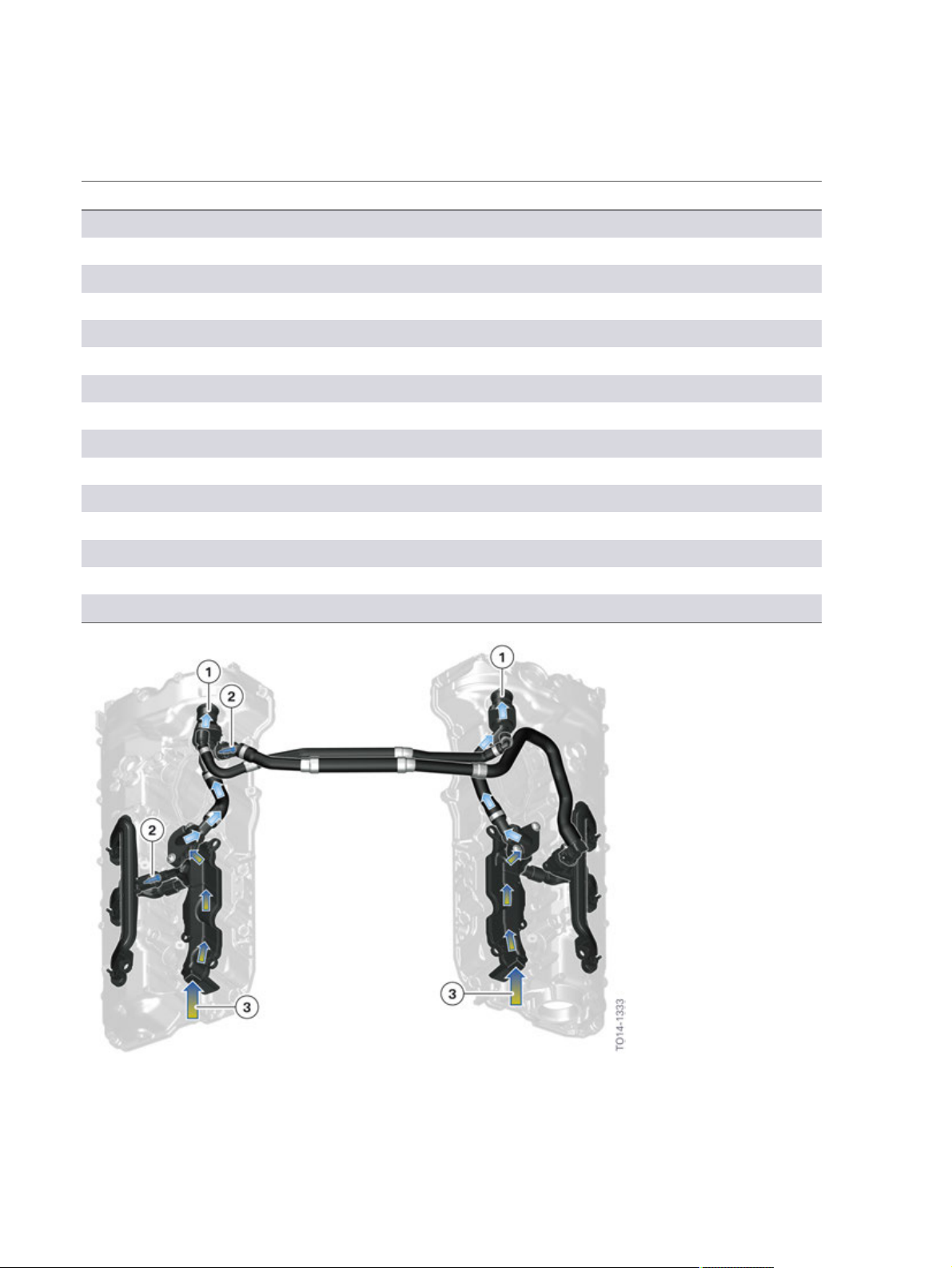
Crankcase�ventilation�in�charged�operation
In�charged�operation�the�pressure�in�the�intake�system�(12)�increases�and�thus�closes�the�volume
control�valves�(3).�As�there�is�a�vacuum�in�this�operating�condition�in�the�clean�air�pipe�(7),�the�nonreturn�valves�(2�and�6)�for�the�clean�air�pipe�thus�open�and�the�cleaned�blow-by�gases�are�conveyed�via
the�compressor�of�the�exhaust�turbocharger�and�the�charge�air�cooler�(9)�into�the�air�intake�system.
22

N63TU2�Engine
2.�Engine�Mechanical
N63TU2�engine,�overview�of�ventilation�in�charged�operation
Index Explanation
A
C Vacuum
D Exhaust�gas
E Oil
F Blow-by�gases
1 Leakage�hole�in�the�housing�of�the�non-return�valve
2 Non-return�valve�for�the�clean�air�pipe�open
3 Volume�control�valves�for�the�intake�system�with�throttle�function,�closed
4 Purge�air�line
5 Intake�pipe�from�bank�2�to�bank�1
Charging�pressure�2.5
+0.3
�bar�absolute
23
N63TU2�Engine
2.�Engine�Mechanical
Index Explanation
6 Line�to�the�clean�air�pipe�with�open�non-return�valve
7 Clean�air�pipe
8 Oil�separator
9 Charge�air�cooler
10 Intake�silencer�with�hot�film�air�mass�meter�8
11 Throttle�valve
12 Intake�manifold
13 Oil�return
14 Ventilation�duct
15 Crank�chamber
16 Oil�sump
17 Exhaust�turbocharger
18 Oil�return�duct
19 Duct�in�the�cylinder�head
20 Non-return�valve
N63TU2�engine,�components�of�the�crankcase�ventilation�in�charged�operation
24
 Loading...