

Page 1

Maintenance instructions for sporty off-roading
HP2 Enduro
Page 2
Motorcycle data/dealership details
Motorcycle data
Model
Vehicle identification number
Colour code
Date of first registration
Registration number
Dealership details
Person to contact in Service department
Ms/Mr
Phone number
Dealership address/phone number
(company stamp)
Page 3

Details described or illustrated in this booklet may
differ from the motorcycle's
actual specification as purchased, the accessories fitted or the national-market
specification. No claims will
be entertained as a result of
such discrepancies.
Dimensions, weights, fuel
consumption and performance data are quoted to the
customary tolerances.
The right to modify designs,
equipment and accessories is
reserved.
Errors and omissions excepted.
© 2005 BMW Motorrad
Not to be reproduced either
wholly or in part without written permission from BMW
Motorrad, After Sales.
Printed in Germany.
Page 4

9
BMW Motorrad
Order No:
01 41 7698 321
08.2005
1st edition GB/RF
BMW recommends
The Ultimate
Riding Machine
Page 5

Maintenance instructions for sporty
off-roading
These maintenance instructions were compiled for riders
who want to leave metalled
roads and use their motorcycles for sporty off-roading.
Before you go off-roading,
BMW Motorrad recommends
installing the accessories
supplied with the motorcycle.
In this way you can effectively
protect parts of the motorcycle that could otherwise be
at risk.
These maintenance instructions describe the procedures for installing the off-road
accessories and the procedure for removing the numberplate carrier and the mirrors.
Use the headlight guard
only when off-roading.
Riding on public roads with
the headlight guard fitted to
the motorcycle is prohibited.
Sporty off-roading inevitably
increases wear and tear on
the motorcycle, so extra
checks and maintenance
work over and above those
described in the Rider's
Manual are necessary. They
too are described in this
publication.
All the work described in
these Maintenance Instructions is supplementary to the
standard maintenance work
described in the "Service"
section of the Rider's Manual.
Please bear in mind that if the
motorcycle is used for sporty
off-roading, you must comply
with these additional maintenance instructions in order to
keep the motorcycle in good
running order.
Some of the work calls for
special tools and a thorough
knowledge of motorcycles.
If you are in doubt consult a
specialist workshop, preferably your authorised BMW
Motorrad dealer.
Damage not attended
to in good time or inadequately repaired can result in
consequential damage to the
motorcycle.
Consult a specialist workshop, preferably an authorised BMW Motorrad dealer,
as soon as possible if you
discover that the motorcycle
is damaged.
Page 6

Table of Contents
You can also consult the index at the end of this Rider's
Manual if you want to find a
particular topic or item of information.
1 General instructions . . . 3
Notes on these
Maintenance
Instructions . . . . . . . . . . . . . . 4
Abbreviations and
symbols . . . . . . . . . . . . . . . . . . 4
2 Overview . . . . . . . . . . . . . . 5
Conversion work
preparatory to
off-roading . . . . . . . . . . . . . . . 6
Maintenance work . . . . . . . . 6
3 Installing and removing
components . . . . . . . . . . . 9
Removing number-plate
carrier . . . . . . . . . . . . . . . . . . 10
Installing number-plate
carrier . . . . . . . . . . . . . . . . . . 11
Removing mirror . . . . . . . . . 12
Installing mirrors . . . . . . . . . 12
Installing headlight
guard . . . . . . . . . . . . . . . . . . . 12
Installing guard for final
drive . . . . . . . . . . . . . . . . . . . . 13
Installing cylinder
guard . . . . . . . . . . . . . . . . . . . 14
Installing deflector for
footbrake lever . . . . . . . . . . 14
Installing left and right
hand protectors . . . . . . . . . 15
Replacing left and right
hand frame-protector
strips . . . . . . . . . . . . . . . . . . . 18
4 Maintenance . . . . . . . . . 19
Work to be carried out
always before
off-roading . . . . . . . . . . . . . . 20
Work to be carried out
after five hours of riding in
sand, dust or mud . . . . . . . 20
Work to be carried out
after ten hours
off-roading . . . . . . . . . . . . . . 25
Work to be undertaken
once a year. . . . . . . . . . . . . . 29
5 Threaded fasteners . . . 31
Anchorage points, engine
and swinging arm . . . . . . . . 33
Anchorage points, frame
and mounted
components. . . . . . . . . . . . . 34
Anchorage points,
front . . . . . . . . . . . . . . . . . . . . 36
Threaded fasteners, front
wheel . . . . . . . . . . . . . . . . . . . 38
Body-panel screws . . . . . . 38
6 Technical data . . . . . . . . 39
Tightening torques for
internally mounted
components. . . . . . . . . . . . . 40
Tightening torques for
checking threading
fasteners . . . . . . . . . . . . . . . . 42
Page 7

General instructions
Notes on these Maintenance
Instructions ..................... 4
Abbreviations and symbols ...... 4
1
3
z
General instructions
Page 8
Notes on these Main-
1
tenance Instructions
4
The work explained in these
Maintenance Instructions
should be carried out in
accordance with the schedule
outlined below. Use the
operating-hours counter
described in the "Operation"
section of the Rider's Manual
to check the operating hours.
Work you must always undertake before leaving surfaced roads for sporty offroading.
Work you must undertake
z
General instructions
after five hours of riding in
mud, dust or sand.
Work you must undertake
after ten hours off-roading.
Work you must undertake
once a year.
You will find detailed information on maintenance and repair work in the Repair Manual on the CD-ROM that accompanies your motorcycle.
Abbreviations and
symbols
Indicates warnings that
you must comply with for
reasons of your safety and the
safety of others, and to protect your motorcycle against
damage.
Specific instructions on
how to operate, control,
adjust or look after items of
equipment on the motorcycle.
Indicates the end of an
item of information.
Instruction.
Result of an activity.
Reference to a page
with more detailed information.
Page 9

Overview
Conversion work preparatory to
off-roading ...................... 6
Maintenance work ............... 6
2
5
z
Overview
Page 10
Conversion work
2
preparatory to
6
off-roading
Removing number-plate
carrier ( 10)
Removing mirror ( 12)
Installing headlight guard
( 12)
Installing guard for final
drive ( 13)
Installing cylinder guard
z
Overview
( 14)
Installing deflector for footbrake lever ( 14)
Installing left and right hand
protectors ( 15)
Maintenance work
Work to be carried
out always before
off-roading
Checking brake disc wear
( 20)
Checking brake pads for
wear ( 20)
Checking spokes ( 20)
Work to be carried out
after five hours of riding
in sand, dust or mud
Checking alternator drive
belt ( 20)
Checking air filter for dirt
( 21)
Checking ease of movement of footbrake lever
( 23)
Checking ease of movement of shift lever ( 24)
Cleaning slider tubes ( 25)
Work to be carried
out after ten hours
off-roading
Checking air filter for dirt
( 21)
Checking ease of movement of footbrake lever
( 23)
Checking ease of movement of shift lever ( 24)
Cleaning slider tubes ( 25)
Checking steering-head
bearing ( 25)
Checking wheel bearing for
play ( 26)
Checking telescopic-fork
protector and slip-ring
( 26)
Bleeding telescopic forks
( 27)
Checking ease of movement of side stand ( 27)
Check operation of sidestand switch ( 27)
Checking spring-strut
mount for play ( 28)
Checking swinging-arm
bearings for play ( 28)
Checking flexible gaiter
( 29)
Page 11

Checking Paralever bearing
for play ( 29)
Checking security of
threaded fasteners ( 29)
Work to be undertaken
once a year
Changing telescopic-fork oil
( 29)
2
7
z
Overview
Page 12

2
8
z
Overview
Page 13

Installing and removing
components
Removing number-plate
carrier ........................ 10
Installing number-plate
carrier ........................ 11
Removing mirror............... 12
Installing mirrors............... 12
Installing headlight guard . . .... 12
Installing guard for final drive . . . 13
Installing cylinder guard........ 14
Installing deflector for footbrake
lever . ......................... 14
Installing left and right hand
protectors . .................... 15
Replacing left and right hand
frame-protector strips ......... 18
3
9
z
Installing and removing components
Page 14
Removing number-
3
plate carrier
10
Make sure the ground is
level and firm and place the
motorcycle on its stand.
Remove the seat.
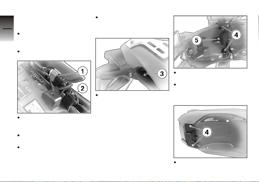
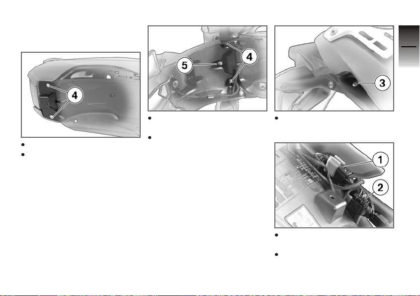
Remove plug 1 from its
holder and disconnect the
plug.
Remove protective plug 2
from its holder.
Connect plug 1 to protective plug 2.
z
Installing and removing components
Push wiring-harness end
of plug 1 into the holder of
protective plug 2.
Remove screws 3 on left
and right.
Remove screws 4 and
screw 5.
Remove the number-plate
carrier and thread out the
cables.
Reinstall screws 4.
Page 15
Installing numberplate carrier
3
11
Remove screws 4.
Manoeuvre the cables into
place and hold the numberplate carrier in position.
Install screws 4 and
screw 5.
Disconnect the numberplate plug and the protective plug.
Install screws 3 on left and
right.
Remove wiring-harness end
of plug 1 from the holder.
Connect plug 1 and seat it
in the holder.
z
Installing and removing components
Page 16
Seat protective plug 2 in its
holder.
3
Install the seat.
12
Installing mirrors
Removing mirror
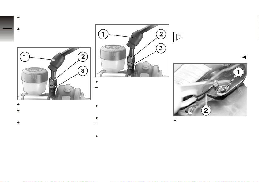
Install clamping piece 3.
Clamping piece to clamping
block
Push back rubber sleeve 1.
Release threaded fastener 2
and remove the mirror.
Remove clamping piece 3.
z
Installing and removing components
30 Nm
Install the mirror and adjust
it to the correct position.
Tighten threaded fastener 2.
Mirror to clamping piece
25 Nm
Slip rubber sleeve 1 down
over the threaded fastener.
Installing headlight
guard
Use the headlight guard
only when off-roading.
Riding on public roads with
the headlight guard fitted to
the motorcycle is prohibited.
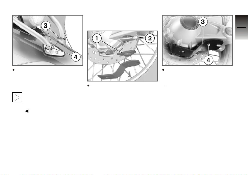
Position the headlight guard
with bore 1 against the instrument carrier from below and secure it with cable
tie 2.
Page 17
Installing guard for
final drive
3
13
Bend the headlight guard
down at the front and use
cable ties 3 to mudguard
struts 4.
In order to avoid injury,
be sure to turn the cable
tie so that the lock is at the
back.
Insert attachment 1 long
end toward the rear into
housing for final drive 2.
Position guard for final
drive 3 on the attachment
and secure it with screw 4.
Guard, final-drive housing
8Nm
z
Installing and removing components
Page 18
Installing cylinder
3
guard
14
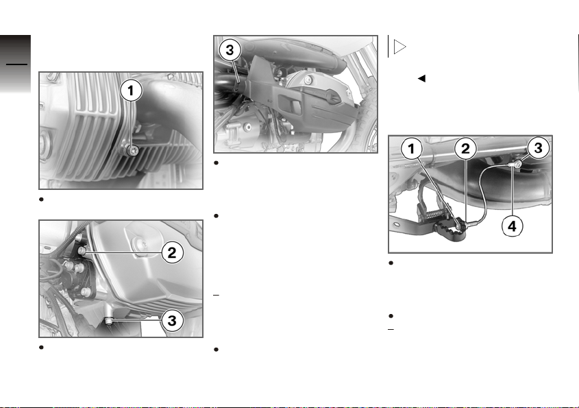
Working from the inside,
insert the front reinforcing
Remove screw 1.
Remove screws 2 and 3.
z
Installing and removing components
plate into the cylinder
guard.
Use the screws and bushings provided to secure the
cylinder guard, inserting
the screws into the tapped
holes left by the screws removed beforehand.
Cylinder guard to engine
Thread-locking compound:
Mechanical thread lock
8Nm
Install cable tie 3.
In order to avoid injury,
be sure to turn the cable
tie so that the lock is at the
back.
Installing deflector for
footbrake lever
Screw threaded pin 2 into
the tapped hole in the footbrake lever until nut 1 can
just be screwed on.
Lock the pin with nut 1.
Footbrake lever deflector to
lever
Hand-tight
Page 19
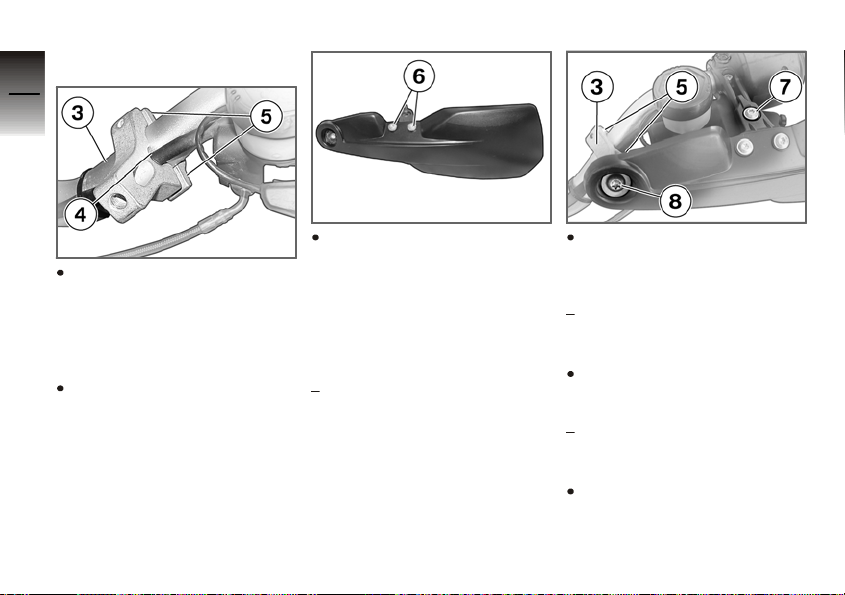
Insert screw 3 through
eye 4 and install it in the
motorcycle's frame. Align
the eye as shown in the
illustration.
Footbrake lever deflector to
frame
5Nm
Remember to remove the
deflector for the footbrake
lever before you next use
the motorcycle on public
roads.
Installing left and right
hand protectors
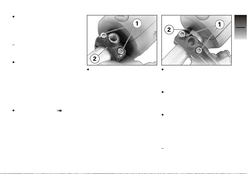
Removing mirror ( 12)
Remove screws 1 and
remove top part of mirror
clamping block 2. Hold the
clutch fitting or handbrake
fitting, as applicable, when
removing the clamping
block.
Install screws 1 of the mirror
clamping block for the hand
protector, but do not tighten
them at this point.
Align the clamping block
so that pin 2 of the grip unit
projects into the gap in the
mirror clamping block.
Tighten screws 1 in such a
way that the gap between
the top and bottom halves
of the clamping block is
the same width at front and
rear.
Handlebar fitting to handlebar
3
15
z
Installing and removing components
Page 20
3
16
Use screws 6 and
Position holders 3 in such
a way that the cables pass
through recess 4. Note the
identifying marks RK for the
right hand protector and LK
for the left hand protector.
Install screws 5, but do not
tighten them at this point.
z
Installing and removing components
washers to secure the
hand-protector holder to
the hand protector. Use
hand-protector holder
7 684 575 for the left side
and 7 684 576 for the right
side.
Hand protector to holder for
hand protector
3Nm
Use screw 7 and washer to
secure the hand-protector
holder to the mirror clamping block.
Holder for hand protector to
mirror clamping block
3Nm
Use screw 8 and washer to
secure the hand protector
to holder 3.
Hand protector to clamping
block
3Nm
Tighten screws 5 of the
holder in such a way that
the gap between the top
and bottom halves of the
Page 21

holder is the same width at
front and rear.
Clamp to clamping block
4Nm
Installing mirrors ( 12)
3
17
z
Installing and removing components
Page 22
Replacing left and
3
right hand frameprotector strips
18
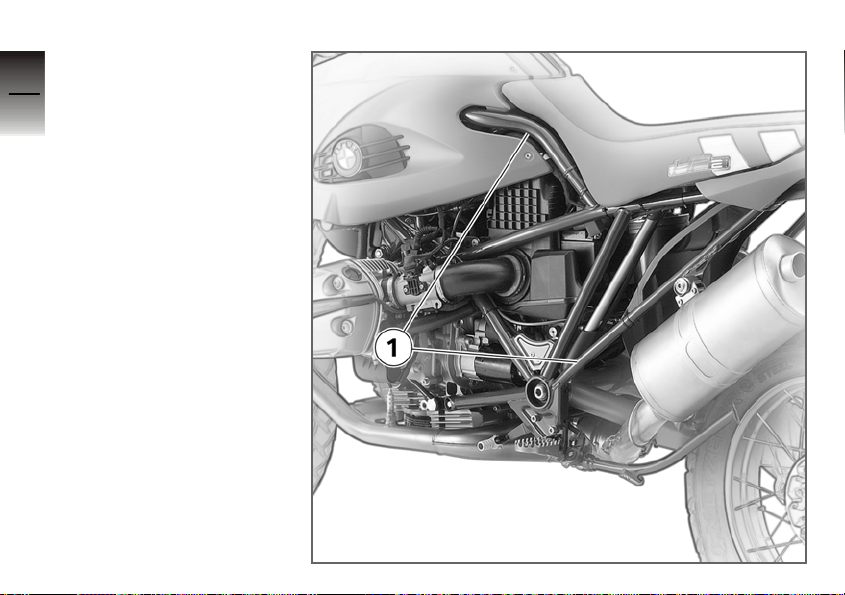
1 Positions of the left and
right protector strips to
be checked and, if necessary, replaced
z
Installing and removing components
Page 23

Maintenance
Work to be carried out always
before off-roading ............. 20
Work to be carried out after five
hours of riding in sand, dust or
mud .......................... 20
Work to be carried out after ten
hours off-roading .............. 25
Work to be undertaken once a
year. . ......................... 29
4
19
z
Maintenance
Page 24
Work to be carried
4
out always before
20
off-roading
Checking brake disc
wear
Consult the following source
for a description of how to
check the brake discs for
wear:
Repair manual on CD-ROM
/ Construction group 34 /
Repair manual
z
Maintenance
Checking brake pads for
wear
Consult the following source
for a description of how to
check the brake pads for
wear:
Repair Manual on CD-ROM
/ Construction group 34 /
Repair manual
Rider's Manual / chapter
entitled "Maintenance"
Checking spokes
Draw the handle of a screwdriver or a similar instrument across the spokes
and listen to the notes of
the individual spokes.
If the notes vary:
Have the spokes checked
by a specialist workshop,
preferably an authorised
BMW Motorrad dealer.
Work to be carried
out after five hours of
riding in sand, dust or
mud
Checking alternator drive
belt
Make sure the ground is
level and firm and place the
motorcycle on its stand.
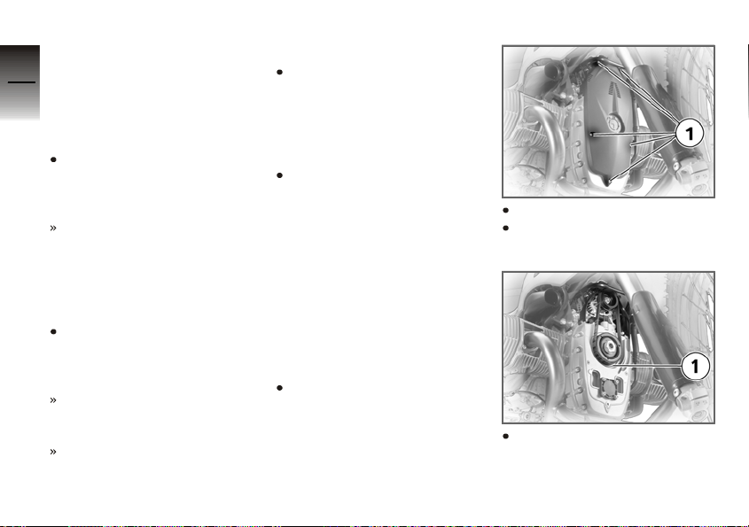
Remove screws 1.
Remove the cover of the
alternator drive belt.
Check for foreign matter on
the belt cover and in the
Page 25
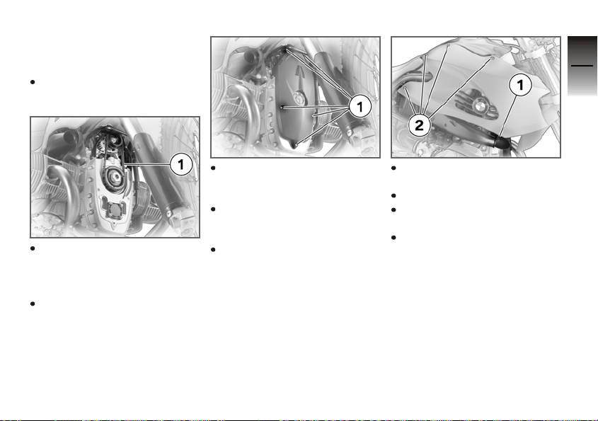
vicinity of alternator drive
belt 1.
If foreign matter has built up:
Remove the foreign-matter
accretions.
4
21
Check alternator drive belt 1
for cracks and wear.
If the belt is cracked or badly
worn:
Have the alternator drive
belt replaced by a special-
ist workshop, preferably an
authorised BMW Motorrad
dealer.
Place the cover of the alternator drive belt in position.
Install screws 1.
Checking air filter for dirt
Make sure the ground is
level and firm and place the
motorcycle on its stand.
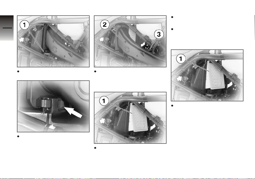
Remove screw 1 from the
intake guard.
Remove the intake guard.
Remove screws 2 from the
side panel.
Remove the right side panel.
z
Maintenance
Page 26
4
22
Check the air filter for dirt.
If the air filter is dirty:
Tap the air filter to remove
foreign matter; replace if necessary
Remove retaining clips 1.
z
Maintenance
To do so, press the rear of
the clip arrow and pull out
the clip.
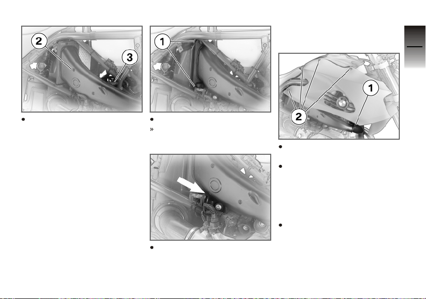
Pull air intake 2 to one side
out of mount 3 and remove
it from the air filter box.
Introduce air filter element 1
into the air filter box from
below.
Pull the air filter element 1
down and out of the air filter
box.
Page 27
the throttle valve is seated
against the stop.
4
23
Working from the side, slip
air intake 2 into mount 3
and the guides on the air
filter box. Make sure that
the air filter is not squashed
inside the air filter box.
Push in retaining clips 1.
The retaining clips engage
with an audible click.
Check that the throttle-valve
cable is seated in the guide
of the intake arrow and that
Install right side panel with
screws 2.
Install intake guard with
screw 1, making sure the
guard is correctly seated.
Checking ease of movement of footbrake lever
Make sure the ground is
level and firm and place the
motorcycle on its stand.
z
Maintenance
Page 28
4
24
Checking ease of movement of shift lever
Make sure the ground is
level and firm and place the
motorcycle on its stand.
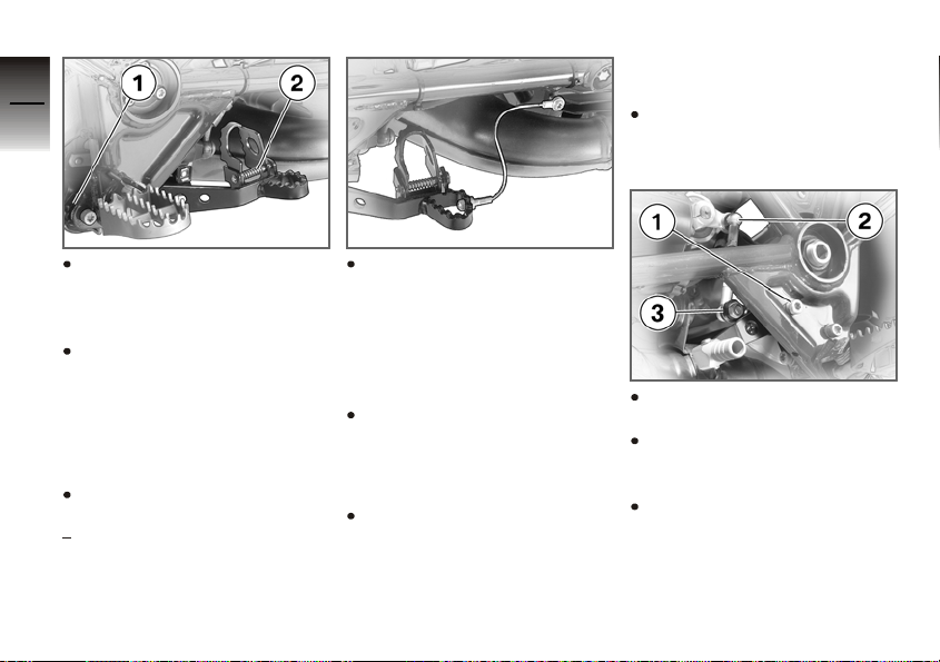
Check the ease of movement of pivot mount 1 and
footrest adjuster 2.
If the pivot mount is stiff:
Have the pivot mount
z
Maintenance
checked by a specialist
workshop, preferably an
authorised BMW Motorrad
dealer.
If the footrest adjuster is stiff:
Lubricate the footrest adjuster.
Staburags NBU 30 PTM
Check the deflector for the
footbrake lever for bent
parts and check that the
footbrake lever is in full
working order.
If parts of the deflector for the
footbrake lever are bent:
Replace the deflector for
the footbrake lever.
If the footbrake lever is not in
full working order:
Restore the footbrake lever
to full working order.
Check the ease of movement of lever pivot 1.
Check the ease of movement at pivots 2 and 3.
If pivots are stiff:
Have the shift lever checked
by a specialist workshop,
preferably an authorised
BMW Motorrad dealer.
Page 29

Cleaning slider tubes
Make sure the ground is
level and firm and place the
motorcycle on its stand.
Use plenty of water to wash
out the space between the
fork protector and the slider
tube.
Use a damp cloth to wipe
clean the right and left slider
tubes. In this process,
be sure to pull the cloth
through between the fork
protector and the slider
tube at the front.
Push left and right sealing
boots 1 down.
Use a dry cloth to wipe dirt
off the sealing boots and
slider tubes.
Pack the groove of each
sealing boot with grease.
Molykote 111
Slide the sealing boots back
up into position.
Work to be carried
out after ten hours
off-roading
Work already described
Checking air filter for dirt
( 21)
Checking ease of movement of footbrake lever
( 23)
Checking ease of movement of shift lever ( 24)
Cleaning slider tubes ( 25)
Checking steering-head
bearing
Place the motorcycle on the
auxiliary stand (see Rider's
Manual).
4
25
z
Maintenance
Page 30
4
26
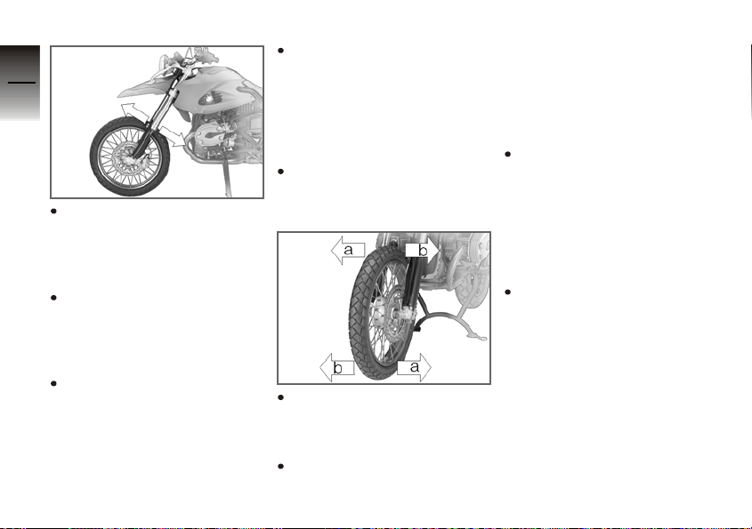
Take a grip at the bottom of
the fixed fork tubes and pull
the forks back and forth.
If the bearing is not free of
play:
z
Maintenance
Have the steering head
bearing adjusted by a
specialist workshop,
preferably an authorised
BMW Motorrad dealer.
Allow the handlebars to
swing left and right from the
straight-ahead position.
If the handlebars feel stiff
or there is a perceptible
notching effect at the
straight-ahead position:
Have the bearing replaced
by a specialist workshop,
preferably an authorised
BMW Motorrad dealer.
Checking wheel bearing
for play
Place the motorcycle on the
auxiliary stand (see Rider's
Manual).
Lift the front wheel clear of
the ground, let it turn and
check whether play is perceptible.
Take a firm grip of the front
wheel at top and bottom,
try to turn the wheel in opposite directions and check
whether play is perceptible
in the bearing.
If there is play in the wheel
bearing:
Have the wheel bearing
checked by a specialist
workshop, preferably an
authorised BMW Motorrad
dealer.
Checking telescopic-fork
protector and slip-ring
Make sure the ground is
level and firm and place the
motorcycle on its stand.
Page 31
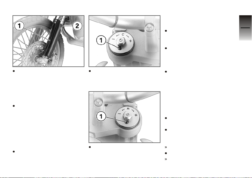
Check for wear at the
insides of left and right
telescopic-fork protectors 1
and check left and right
slip-rings 2 for wear.
If evidence of wear is visible:
Have the condition of the
telescopic-fork protectors
and the slip-rings checked
by a specialist workshop,
preferably an authorised
BMW Motorrad dealer.
Bleeding telescopic forks
Make sure the ground is
level and firm and place the
motorcycle on its stand.
Back off and then retighten
screw 1 on the left in the
fork bridge.
Back off and then retighten
screw 1 on the right in the
fork bridge.
Checking ease of movement of side stand
Place the motorcycle on the
auxiliary stand (see Rider's
Manual).
Extend and retract the side
stand to check the freedom
of its movement.
If the side stand is stiff:
Have the side stand
checked by a specialist
workshop, preferably an
authorised BMW Motorrad
dealer.
Check operation of sidestand switch
Switch off the engine and
extend the side stand.
With the clutch disengaged,
switch on the ignition and
start the engine.
The engine starts.
Engage first gear.
The engine cuts out.
4
27
z
Maintenance
Page 32
If the engine does not cut out:
4
Have the side-stand switch
checked by a specialist
28
workshop, preferably an
authorised BMW Motorrad
dealer.
Checking spring-strut
mount for play
Make sure the ground is
level and firm and place
the motorcycle on its side
stand.
Remove the seat.
z
Maintenance
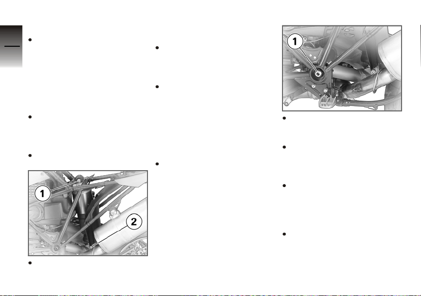
Lay one hand on top springstrut mount 1 and push the
motorcycle against the side
stand.
Repeat this check at bottom
spring-strut mount 2.
If the mounts are not free of
play:
Have the spring-strut
mounts checked by a
specialist workshop,
preferably an authorised
BMW Motorrad dealer.
Checking swinging-arm
bearings for play
Place the motorcycle on the
auxiliary stand (see Rider's
Manual).
Place one hand on the
swinging-arm bearing and
the frame on the left.
Move the rear wheel to left
and right, while checking for
play in swinging-arm bear-
ing 1.
Repeat the procedure for
the right swinging-arm bear-
ing.
If the bearings are not free of
play:
Have the swinging-arm
bearings checked by
a specialist workshop,
preferably an authorised
BMW Motorrad dealer.
Page 33
Checking flexible gaiter
Make sure the ground is
level and firm and place
the motorcycle on its side
stand.
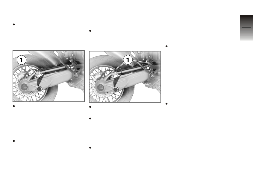
Check that flexible gaiter 1
is correctly seated and free
of cracks.
If the flexible gaiter has
worked loose or if cracks are
visible:
Have the flexible gaiter
checked by a specialist
workshop, preferably an
authorised BMW Motorrad
dealer.
Checking Paralever
bearing for play
Place the motorcycle on the
auxiliary stand (see Rider's
Manual).
Place one hand on the
Paralever bearing.
Move the rear wheel to left
and right, while checking for
play in Paralever bearing 1.
If the bearings are not free of
play:
Have the Paralever bearings checked by a specialist workshop, preferably an
authorised BMW Motorrad
dealer.
Checking security of
threaded fasteners
Check the security of the
threaded fasteners, as described in the section entitled "Threaded fasteners".
Work to be undertaken
once a year
Changing telescopic-fork
oil
Have the oil in the telescopic forks changed by a specialist workshop, preferably
an authorised BMW Motorrad dealer.
4
29
z
Maintenance
Page 34

4
30
z
Maintenance
Page 35

Threaded fasteners
Anchorage points, engine and
swinging arm . . . ............... 33
Anchorage points, frame and
mounted components ......... 34
Anchorage points, front ........ 36
Threaded fasteners, front
wheel ......................... 38
Body-panel screws . . . ......... 38
5
31
z
Threaded fasteners
Page 36
5
32
z
Threaded fasteners
Page 37

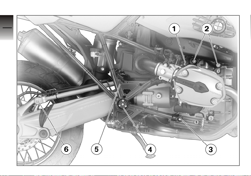
Anchorage points, engine and swinging arm
1 Rear frame section to
engine at top, left and
right
2 Frame front section to
engine, left and right
3 Rear frame section to en-
gine at bottom, left and
right
4 Swinging arm to rear
frame section, right
5 Reaction link to frame
6 Reaction link to final-
drive housing
If a locking compound is
specified for a threaded
fastener in the table of
torques, be sure to comply
with the instructions in the
appropriate chapter of the
Repair Manual on CD-ROM.
5
33
z
Threaded fasteners
Page 38
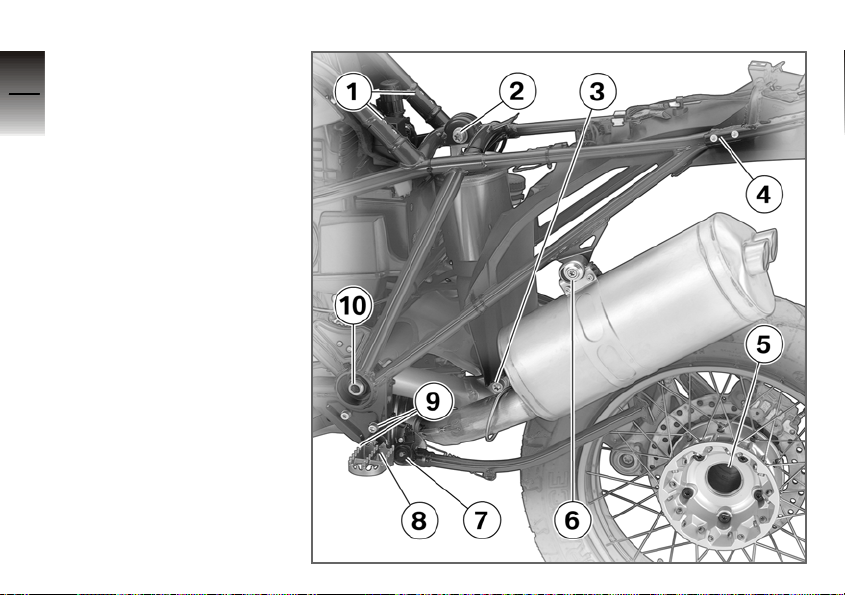
Anchorage points,
5
frame and mounted
components
34
1 Frame front section to
rear frame section, left
and right
2 Spring strut to rear frame
3 Spring strut to rear
swinging arm
4 Rear carrier to rear frame
section, left and right
5 Rear wheel to wheel car-
rier
6 Rear silencer to rear
frame section
7 Side stand to pivot
z
Threaded fasteners
mount
8 Stop screw, front
footrest, left, to
side-stand pivot mount
9 Pivot mount, side stand
to rear frame section
10 Swinging arm to rear
frame section, left
Page 39

If a locking compound is
specified for a threaded
fastener in the table of
torques, be sure to comply
with the instructions in the
appropriate chapter of the
Repair Manual on CD-ROM.
5
35
z
Threaded fasteners
Page 40
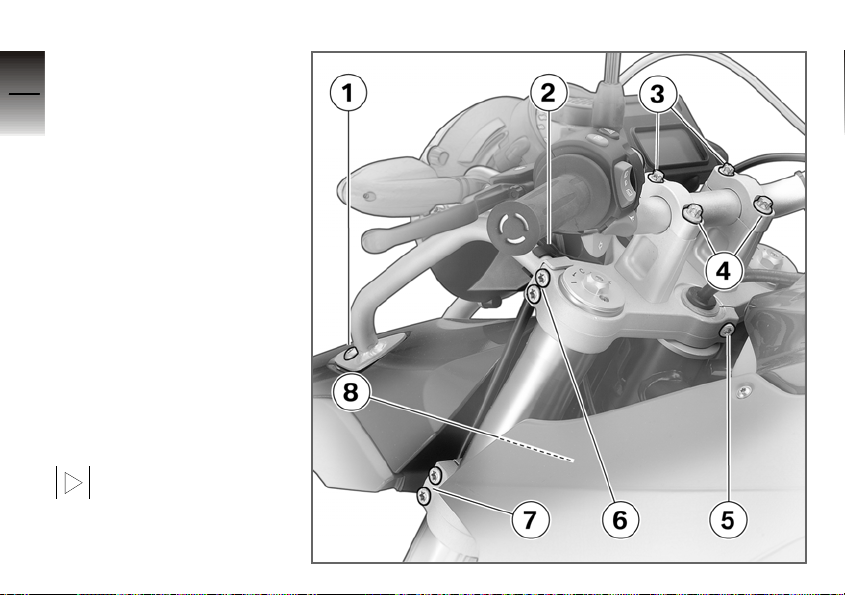
Anchorage points,
5
front
36
1 Front mudguard to head-
light, left and right
2 Mudguard carrier to top
fork bridge, left and right
3 Handlebars to handlebar
clamping blocks, left and
right
4 Handlebar clamping
block to fork bridge
5 Fork bridge to steering
tube
6 Top fork bridge to fixed
fork tube, left and right
7 Bottom fork bridge to
z
fixed fork tube, left and
Threaded fasteners
right
8 Mudguard carrier to fork
bridge, bottom
If a locking compound is
specified for a threaded
fastener in the table of
torques, be sure to comply
with the instructions in the
Page 41

appropriate chapter of the
Repair Manual on CD-ROM.
5
37
z
Threaded fasteners
Page 42
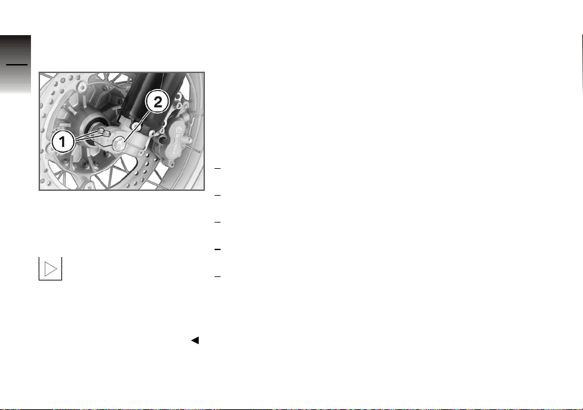
Threaded fasteners,
5
front wheel
38
1 Pinch bolt, axle holder,
left and right
2 Front wheel, axle screw
in axle holder
z
Threaded fasteners
If a locking compound is
specified for a threaded
fastener in the table of
torques, be sure to comply
with the instructions in the
appropriate chapter of the
Repair Manual on CD-ROM.
Body-panel screws
The body-panels crews listed
below are locked by means
of nylon thread and are handtightened.
Check the locking effect of
the nylon threads and the security of the screws.
Body-panel screws
Five screws in each front
body panel, left and right.
Two screws in each rear
body panel, left and right.
Four screws in the protector
for the rear light.
Nine screws in the bottom
front mudguard.
Five screws in the numberplate carrier.
Page 43

Technical data
Tightening torques for internally
mounted components ......... 40
Tightening torques for checking
threading fasteners . . . ......... 42
6
39
z
Technical data
Page 44
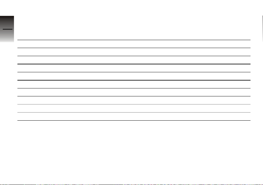
Tightening torques for internally mounted components
6
Activity Type of threaded connection Tightening
40
Mirrors
Clamping piece to clamping block M10 30 Nm
Mirror to clamping piece M10 25 Nm
Guard for final drive
Guard, final-drive housing 8 Nm
Cylinder guard
Cylinder guard to engine M6 x 20, Mechanical thread lock 8 Nm
Deflector, footbrake lever
z
Technical data
Footbrake lever deflector to lever Nut M5 Hand-tight
Footbrake lever deflector to frame 5 Nm
torques
Page 45
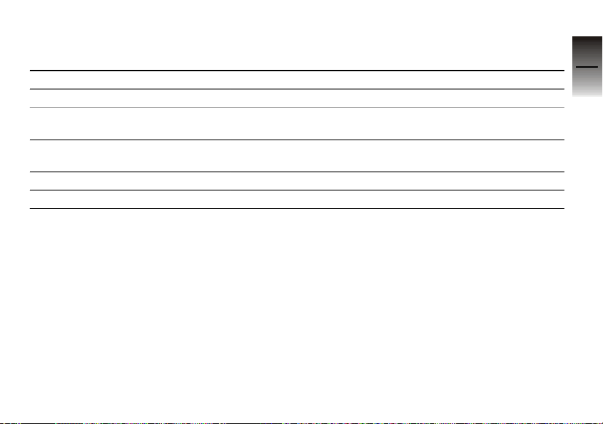
Activity Type of threaded connection Tightening
torques
Hand protectors
Handlebar fitting to handlebar M5 x 20 5 Nm
Hand protector to holder for hand
protector
Holder for hand protector to mirror
clamping block
Hand protector to clamping block M8 x 16 3 Nm
Clamp to clamping block M5 x 12 4 Nm
M5 x 14 3 Nm
M5 x 14 3 Nm
6
41
z
Technical data
Page 46
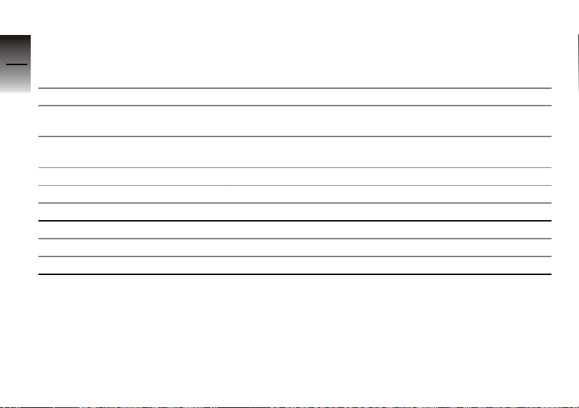
Tightening torques for checking threading fasteners
6
Activity Type of threaded connection Tightening
42
Frame
Frame front section to rear frame
section
Frame front section to engine
front / rear
Rear frame to engine, bottom M12 x 50 55 Nm
Rear frame to engine, top M10 x 40 38 Nm
Rear carrier to rear frame section M6 x 25 8 Nm
Link
z
Technical data
Reaction link to final-drive housing M10 x 55 10.9, Mechanical thread lock 43 Nm
Reaction link to rear frame section M10 x 50 10.9 38 Nm
M8 x 20 19 Nm
M12, Micro-encapsulated 66 Nm
torques
Page 47
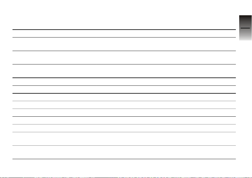
Activity Type of threaded connection Tightening
torques
Rear wheel swinging arm
Swinging arm to rear frame section, left, locknut
Swinging arm to rear frame section, left, bearing stud
Swinging arm to rear frame section, right
Rear wheel
Rear wheel to wheel carrier M10 x 53 x 1.25 60 Nm
Spring strut
Spring strut to rear swinging arm M12 66 Nm
Spring strut to rear frame M12 66 Nm
Side stand
Side stand to pivot mount M10 x 1, Loctite 603 41 Nm
Pivot mount, side stand to rear
frame section
Front footrest stop screw to sidestand pivot mount
M24 x 1.25 145 Nm
M24 x 1.25 7 Nm
M6 9 Nm
M8 x 16, Micro-encapsulated 19 Nm
M8, Micro-encapsulated 19 Nm
6
43
z
Technical data
Page 48
Activity Type of threaded connection Tightening
6
44
Rear silencer
Rear silencer to rear frame section M8 x 45 19 Nm
Handlebars
Handlebar clamping block to fork
bridge
Handlebar to handlebar clamping
block
Fork bridge, top, to steering tube M8 x 30 24 Nm
Front mudguard
Mudguard carrier to fork bridge,
z
Technical data
top
Mudguard carrier to fork bridge,
bottom
Front mudguard to headlight
carrier
Clamps, slider tubes
Fork bridge, top, to fork fixed tube M8 x 30 24 Nm
Fork bridge, bottom, to fork fixed
tube
M10 x 100, grease thread, Optimoly TA 38 Nm
M8 x 30, grease thread, Optimoly TA 19 Nm
M6 x 16 A2-70 special steel, bright, Optimoly TA
M6 x 16 A2-70 special steel, bright, Optimoly TA
M8 x 20 20 Nm
M8 x 30 10 Nm
torques
10 Nm
10 Nm
Page 49
Activity Type of threaded connection Tightening
torques
Front wheel
Front wheel, axle screw in axle
holder
Pinch bolt, axle holder M6 x 30 8 Nm
M22 x 1.5 - Elox H, Optimoly TA 50 Nm
6
45
z
Technical data
Page 50

A
Abbreviations and symbols, 4
7
Accessories
46
Installation, 6, 9
Air filter
Test, 21
Alternator drive belt
Test, 20
B
Brake discs
z
Index
Test, 20
Brake pads
Test, 20
C
Cylinder guard
Installation, 14
D
Deflector, footbrake lever
Installation, 14
F
Final-drive guard
Installation, 13
Flexible gaiter
Test, 29
Footbrake lever
Test, 23
Frame-protector strips
Overview, 18
H
Hand protectors
Installation, 15
Headlight guard
Installation, 12
M
Maintenance
After five hours offroading, 6, 20
After ten hours offroading, 6, 25
Always before offroading, 6, 20
Annually, 7, 29
Mirrors
Installation, 12
Removal, 12
N
Number-plate carrier
Installation, 11
Removal, 10
P
Paralever
Checking bearing, 29
S
Shift lever
Test, 24
Side stand
Checking switch, 27
Test, 27
Slider tubes
Cleaning, 25
Slip-ring
Test, 26
Spokes
Test, 20
Spring strut
Test, 28
Steering-head bearing
Test, 25
Page 51

Swinging arm
Checking bearing, 28
T
Telescopic fork
Bleeding, 27
Changing oil, 29
Checking protector, 26
Threaded fasteners
Body panels, 38
Engine and swinging
arm, 33
Frame and mounted
components, 34
General view, front, 36
General view, front
wheel, 38
Test, 29
Torques, 40
W
Wheel bearing
Test, 26
47
z
7
Index
 Loading...