

Blomberg DWT 15210 NBL00, DWT 15220 NBL00, DW 15111 NBL00, DW 15121 NBL00, DWT 14240 NBL00 Service Manual
...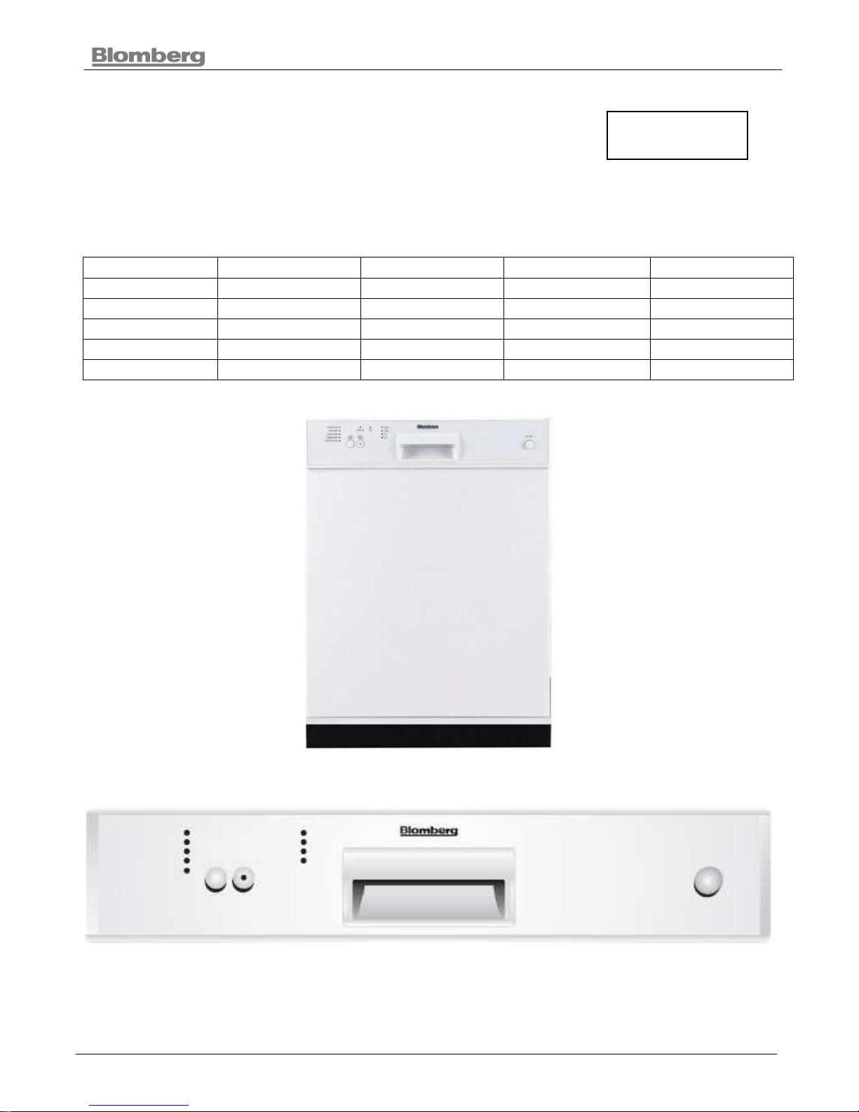
BUILT- UNDER DISHWASHER
1 2011
BUILT - UNDER DISHWASHER
SERVICE USER MANUAL
For Models
DW 14110 NBL00 DW 15111 NBL00 DWT 15210 NBL00 DWT 14210 NBL00 DWT 15210 NBL00
DW 14120 NBL00 DW 15121 NBL00 DWT 15220 NBL00 DWT 14240 NBL00 DWT 15220 NBL00
DW 14140 NBL00 DW 15141 NBL00 DWT 15240 NBL00 DWT 14220 NBL00 DWT 15240 NBL00
DW 15110 NBL00 DWT 14210 NBL00 DWT 15211 NBL00 DWT 14440 ULTRA DWT 15211 NBL00
DW 15120 NBL00 DWT 14240 NBL00 DWT 15241 NBL00 DWT 14410 ULTRA DWT 15241 NBL00
DW 15140 NBL00 DWT 14220 NBL00 DWT 15221 NBL00 DWT 14420 ULTRA DWT 15221 NBL00

BUILT- UNDER DISHWASHER
2 2011
CONTENTS Page No
1. Cover........................................................................................................................................ 1
2. Contents................................................................................................................................. 2
3. Introduction ............................................................................................................................... 5
3.1. Important Safety Instructions .............................................................................................. 5
3.2. Installation ........................................................................................................................... 6
4. Getting To Know Your Dishwasher ........................................................................................... 8
4.1. Technical Instructions (Only one model sample) ................................................................ 9
5. Installation Manual .................................................................................................................. 14
5.1. Important Safety Instructions ............................................................................................ 14
5.1.1. Inspect The Dishwasher ............................................................................................. 15
5.1.2. How To Contact Us .................................................................................................... 15
5.2. Tools Which May Be Needed ........................................................................................... 16
5.3. Materials Which May Be Needed ...................................................................................... 16
5.4. Materials Supplied ............................................................................................................ 17
5.4.1. Parts Supplied ............................................................................................................ 17
5.4.2. Manual Bag ................................................................................................................ 17
5.4.3. Dishwasher Parts Bag 1 ............................................................................................. 17
5.4.4. Dishwasher Parts Bag 2 ............................................................................................. 17
5.4.5. Parts Attached To The Rear Of The Dishwasher ....................................................... 17
5.5. Dishwasher Specifications ................................................................................................ 18
5.6. Technical Features ........................................................................................................... 18
5.7. Enclosure Preparation ...................................................................................................... 18
5.7.1. Electrical Preparation ................................................................................................. 19
5.8. Preparation For Installing Mounting Brackets ................................................................... 20
5.9. Adjusting Height ................................................................................................................ 20
5.9.1. Installing The Foot Supports ...................................................................................... 21
5.10. Installing The Side Trim Strips ....................................................................................... 22
5.11. Preparing The Water Connection (A) ............................................................................ 23
5.11.1. Installing The 90° Elbow Fitting (B) .............. ........................................................... 23
5.11.2. Junction Box Preparation (C) .................................................................................. 23
5.12. Drain Preparation .......................................................................................................... 24
5.12.1. Under The Sink Drain.............................................................................................. 24
5.12.2. Installing An Air Gap ............................................................................................... 24
5.12.3. Disposal .................................................................................................................. 24
5.13. Steam Protection Foil .................................................................................................... 25
5.13.1. Fitting The Protection Foil ....................................................................................... 25
5.14. Placement Of Dishwasher Into The Opening ................................................................. 26
5.15. Drain Hose Connection, Water Supply & Electrical Connections .................................. 26
5.15.1. Drain Hose Connection ........................................................................................... 26
5.15.2. Water Supply Connection ....................................................................................... 27
5.15.3. Braided Hose/Copper Tubing .................................................................................. 27
5.16. Electrical Connection ..................................................................................................... 27
5.16.1. Grounding Instructions ............................................................................................ 27
5.16.2. Fasten Junction Box................................................................................................ 28
5.17. Readjusting Foot Levels ................................................................................................ 29
5.18. Adjusting The Movable Toe Kick ................................................................................... 29
5.19. Installing The Outer Door............................................................................................... 30
5.20. Installer Checklist .......................................................................................................... 35
5.21. Final Instructions ........................................................................................................... 35
5.22. Self Help Hints: .............................................................................................................. 35
6. Loadıng The Dıshwasher ........................................................................................................ 36

BUILT- UNDER DISHWASHER
3 2011
6.1. Proper And Improper Loadıng Of Dıshware ...................................................................... 37
6.2. What Should Not Be Washed In Your Dishwasher ........................................................... 38
7. Operating The Dishwasher ..................................................................................................... 39
7.1. How To Use Your Dıshwasher: ......................................................................................... 39
7.1.1. Functıon Buttons ........................................................................................................ 40
7.2. Rinse aid level indicator light (depending on model) ......................................................... 41
7.3. Salt level indicator light (depending on model) ................................................................. 41
7.4. Program follow up lights .................................................................................................... 41
7.5. Detergent & Rınse Aıd Dıspenser ..................................................................................... 41
7.6. Filling The Detergent Dispenser Warning ......................................................................... 41
7.6.1. Filling Rinse Aid Dispenser ........................................................................................ 43
7.7. Settıng The Water Softener (Dependıng On Model) ......................................................... 43
7.8. Filling The Dishwasher Salt Dispenser (Dependıng On Model) ........................................ 45
7.9. Care And Maıntenance ..................................................................................................... 46
7.10. Carıng For Your Dıshwasher Exterıor ........................................................................... 46
7.11. Caring For Your Dishwasher Interior ............................................................................. 47
7.11.1. Cleanıng The Fılters................................................................................................ 47
7.11.2. Cleaning The Spray Arms ....................................................................................... 48
8. Working Principle .................................................................................................................... 49
8.1. Hydraulic System (Water Softener Group) ....................................................................... 49
8.2. Hydraulic System (No water Softener Group) .................................................................. 51
8.3. Program Flow ................................................................................................................... 52
9. Component Principle............................................................................................................... 53
9.1. Heater (Thermostat And Thermic Fuse) ........................................................................... 53
9.2. Drain Motor ....................................................................................................................... 53
9.3. Circulation Motor ............................................................................................................... 54
9.4. Detergent Dispenser- Thermic Actuator ............................................................................ 54
9.5. Door lock switch ................................................................................................................ 55
9.6. Turbıdıty Sensor ............................................................................................................... 55
9.7. NTC .................................................................................................................................. 56
9.8. On/Off Swıtch ................................................................................................................... 56
9.9. Water Inlet Valve............................................................................................................... 57
9.10. Water Counter ............................................................................................................... 57
9.11. Float Swicth ................................................................................................................... 57
10. Service Functional Test ........................................................................................................ 58
10.1. Faulty Condıtıons .......................................................................................................... 59
10.1.1. 3 Way Valve Position Error (4th program led) .......................................................... 59
10.1.2. NTC Fault (3rd Program Led) .................................................................................. 59
10.1.3. Heating Fault (3rd Program Led).............................................................................. 60
10.1.4. No Water and Counter Fault (2rd Program Led) ...................................................... 60
10.1.5. Uninterruptible Water Inlet Error (1
st
Program Led) ................................................ 60
11. Trouble Shooting .................................................................................................................. 61
11.1. Machine Is Not Running ................................................................................................ 61
11.2. No Water Inlet To The Machine ..................................................................................... 62
11.3. Machine Takes More Water Overflows .......................................................................... 63
11.4. Program Is Not Running ................................................................................................ 64
11.5. Program Is Not Complette ............................................................................................. 65
11.6. Machine Is Not Draining ................................................................................................ 66
11.7. Machine Is Not Circulating ............................................................................................. 67
11.8. Machine Does Not Heat ................................................................................................. 68
11.9. Dispenser Cover Does Not Open .................................................................................. 69
11.10. Problems Which Are Not Detected During Functional Test ........................................ 70
12. Circuit - Whiring - PCB Diagram ........................................................................................... 75

BUILT- UNDER DISHWASHER
4 2011
13. Assembly And Dısassembly Methods For Key Components ............................................... 81
13.1. Control Panel ................................................................................................................. 81
13.2. Panel Group .................................................................................................................. 81
13.3. Display Group ................................................................................................................ 82
13.4. On-Off Button Key Holder .............................................................................................. 82
13.5. Overflow Gauge ............................................................................................................. 83
13.6. Drain Pump .................................................................................................................... 83
13.7. NTC ............................................................................................................................... 83
13.8. Heater ............................................................................................................................ 84
13.9. Circulation Pump ........................................................................................................... 84
13.10. Feedıng Pıpe Of The Upper Spray Arm And Fılter Support ....................................... 85
13.11. Side Walls .................................................................................................................. 85
13.12. Regeneratıon Contaıner ............................................................................................. 85
13.13. Flow-Meter ................................................................................................................. 86
13.14. Hinge Plates ............................................................................................................... 86
13.15. Detergent Container ................................................................................................... 86
13.16. Draın Hose, Water Inlet Valve, And Clıp Box ............................................................. 87
13.17. Bottom Layout ............................................................................................................ 88
14. Explode View ....................................................................................................................... 90
14.1. Main Body ...................................................................................................................... 90
14.2. Inner Tub ....................................................................................................................... 91
14.3. Door group. .................................................................................................................... 92
14.4. Panel Group .................................................................................................................. 93
BUILT- UNDER DISHWASHER
5 2011
3. Introduction
Please read this user manual and particularly the safety instructions completely and carefully They
will save you time and effort and help to ensure optimum dishwasher performance. Be sure to
observe all listed warnings and cautions. Look particularly for the icons with exclamation marks
inside. The information icon will also provide important references.
Indicates a potentially hazardous situation which, if not avoided, could result in
death or serious injury
Indicates a potentially hazardous situation which, if not avoided, may result in
injury. It may also be used to alert against unsafe practices.
Indicates a potentially hazardous situation which, if not avoided, may result in
damage to the dishwasher, the table-ware, the equipment or the environment.
3.1. Important Safety Instructions
When using the dishwasher, follow basic precautions, including the following:
Read all instructions before using the dishwasher! Save these operating
instructions and pass them on to any future user.
Use the dishwasher only for its intended purpose as described in this user manual. This
appliance is intended for normal household use only.
The manufacturer disclaims responsibility for damage or injury caused by improper use of this
appliance.
The information in this user manual must be followed to minimize the risk of fire or
explosion and to prevent property damage, personal injury or loss of life.
Do not operate your dishwasher unless all the enclosure panels are properly in place.
Do not tamper with the controls.
Do not abuse, sit on, stand in or on the door or dish rack of the dishwasher.
The cup racks are designed to support cups, glasses and kitchen utensils. When the cup
racks are in the dishwasher do not lean on or use the cup racks to support your body
weight.
To reduce the risk of injury, do not allow children to play in, on or near the dishwasher.
Use only detergents or rinse aids recommended for use in a household dishwasher and
keep them in a dry place out of the reach of children. Check that the detergent dispenser is
empty after the completion of each wash program.
Dishwasher detergents are alkaline. They can be dangerous if inhaled or swallowed. Avoid
contact with skin and eyes and keep children and infirm persons away from the dishwasher
when the door is opened. Consult a doctor immediately if detergent has been swallowed or
inhaled.
Do not drink water from the dishwasher! Harmful residues could be present.

BUILT- UNDER DISHWASHER
6 2011
Under certain conditions hydrogen gas may be produced in a hot water heater system that
has not been used for two weeks or more. Hydrogen gas is explosive. If the hot water
system has not been used for such period, before using the dishwasher turn on all hot
water taps and let the water flow from each for several minutes. This will release any
accumulated hydrogen gas. As gas is flammable, do not smoke or use an open flame
during this time.
Do not store or use flammable liquids or vapors in the area of the dishwasher.
When loading items to be washed, position sharp items so that they are not likely to
damage the door seal and load sharp knives with the handles up to reduce the risk of cuttype nuries.
Do not wash plastic items unless they are marked “dishwasher safe” or the equivalent. For
plastic items not so marked, check the manufacturer’s recommendations.
If a malfunction occurs, switch off the appliance and turn off the water supply to the
dishwasher.
Before cleaning or carrying out maintenance, switch off the appliance, disconnect the power
plug and turn off the water supply.
Repairs and technical modifications must be carried out exclusively by a qualified
technician.
If the dishwasher is not in use for an extended period of time (i.e. vacation home), we
recommend you check that the baskets are empty, leave the inside of the dishwasher
clean, leave the door cracked open to allow air to circulate and turn off both the power and
water supply to the dishwasher.
3.2. Installation
When installing the dishwasher, follow basic precautions, including the
following:
The dishwasher installation must be performed in accordance with the installation manual.
If you did not receive an installation manual order it by calling 1-800-459-9848 or you may
also download it from our web site at www.blombergappliances.com
Installation, maintenance and repair should be performed by a qualified installer. Work by
unqualified persons could be dangerous and may void the warranty.
Do not operate the appliance if damaged, malfunctioning, partially disassembled or if it has
missing or broken parts.
Before installation or service, disconnect the power supply to the work area by unplugging
the unit, “tripping” the circuit breaker or removing the fuse.
Only connect the dishwasher to the power supply when all installation and plumbing work is
complete.
Do not install or store the dishwasher where it can be exposed to below freezing
temperatures or exposed to weather.

BUILT- UNDER DISHWASHER
7 2011
Dishwasher must be secured to adjacent cabinetry using the brackets provided. Failure to
do this may cause damage to property or bodily injury.
The dishwasher installation must be performed in accordance with the installation manual.
If you did not receive an installation manual order it by calling 1-800-459-9848 or you may
also download it from our web site at
www.blombergappliances.com
Installation, maintenance and repair should be performed by a qualified installer. Work by
unqualified persons could be dangerous and may void the warranty.
Do not operate the appliance if damaged, malfunctioning, partially disassembled or if it has
missing or broken parts.
Before installation or service, disconnect the power supply to the work area by
unplugging the unit, “tripping” the circuit breaker or removing the fuse.
Only connect the dishwasher to the power supply when all installation and plumbing work is
complete.
Do not install or store the dishwasher where it can be exposed to below freezing
temperatures or exposed to weather. cabinetry using the brackets provided. Failure to do
this may cause damage to property or bodily injury.
Danger of suffocation! Ensure that any plastic wrappings, bags, small
pieces etc. are disposed of safely and kept out of the reach of children.
Remove the door to the washing compartment when removing an old dishwasher from
service or discarding it. Ensure that the appliance presents no danger to children while
being stored for disposal.
Old appliances may contain materials that can be recycled. Please contact your local
recycling authority about the possibility of recycling these materials.
BUILT- UNDER DISHWASHER
8 2011
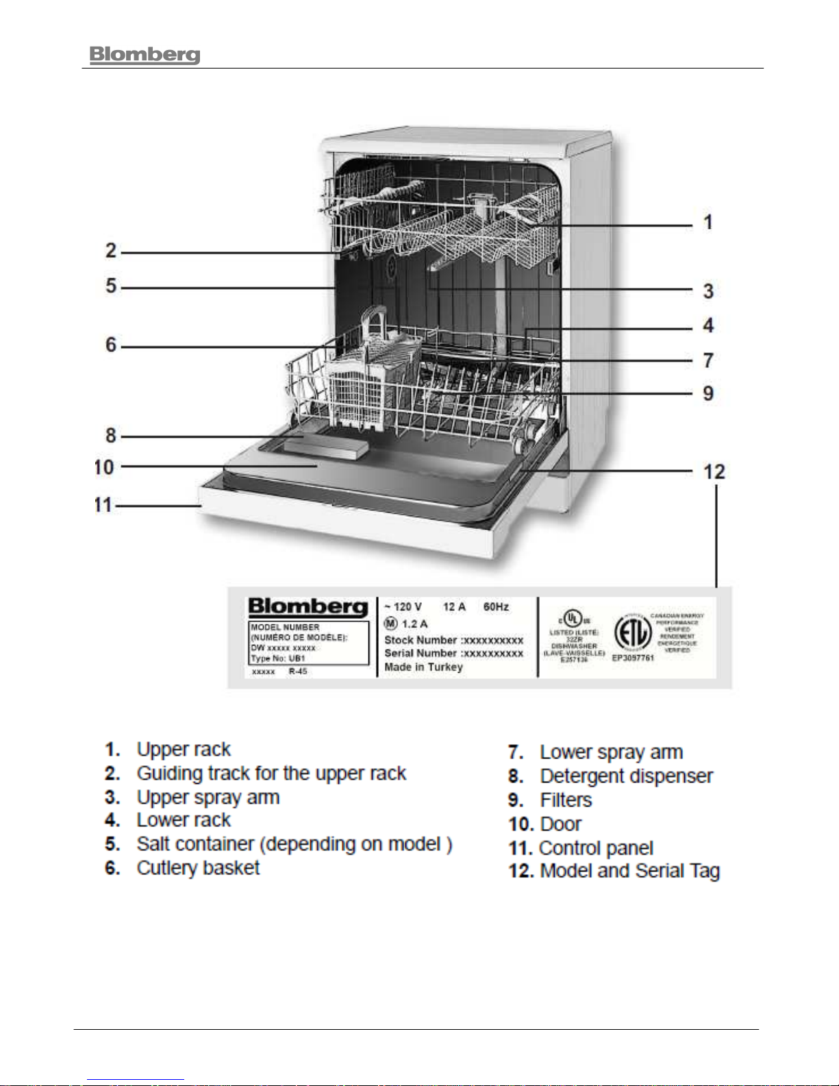
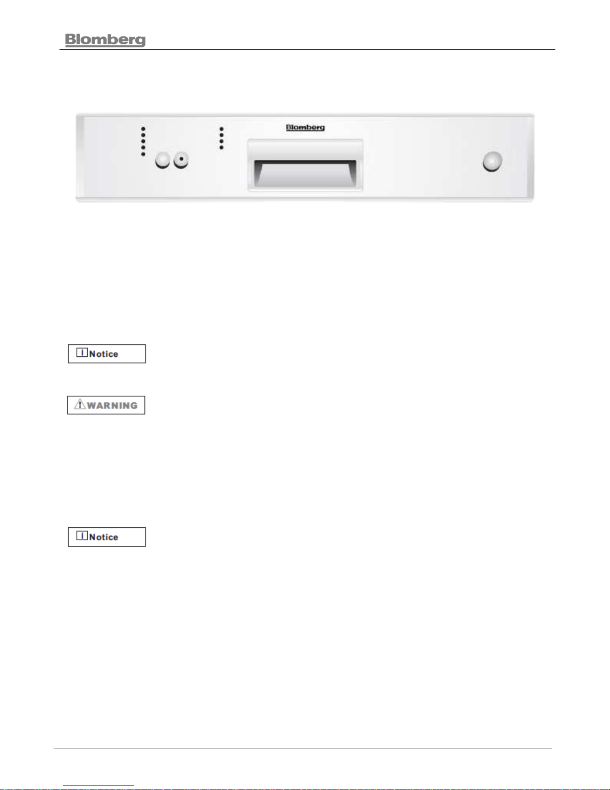
4. Getting To Know Your Dishwasher
BUILT- UNDER DISHWASHER
9 2011
4.1. Technical Instructions (Only one model sample)
Basic Definitions
Brand Blomberg
SAP Code 7665389542
Marketing Code DW 14110 NBL00
Manufacturer Productıon Code 94001
EAN Code 8690769665385
Product Button Ctrl - 4 Prg - Without Water Softener - Red Led
Type Bu 60
Product Type Built-Under
Product Color White
Product Width 60
Loading Capacity (Place
Settings)
12
Technical Details
Voltage (V) 120
Connected Value (W) 1200
Heating Element (W) 1000
Maxımum Current Intensıty (A) 12
Water Supply Connection 3/4 Yes
Water Pressure Range (N/Cm2) 3 To 100
Connection To Warm Water Up
To (°C)
60 C
Wide Tub Strip No
Electrical Data
Frequency (Hz) 60 Hz

BUILT- UNDER DISHWASHER
10 2011
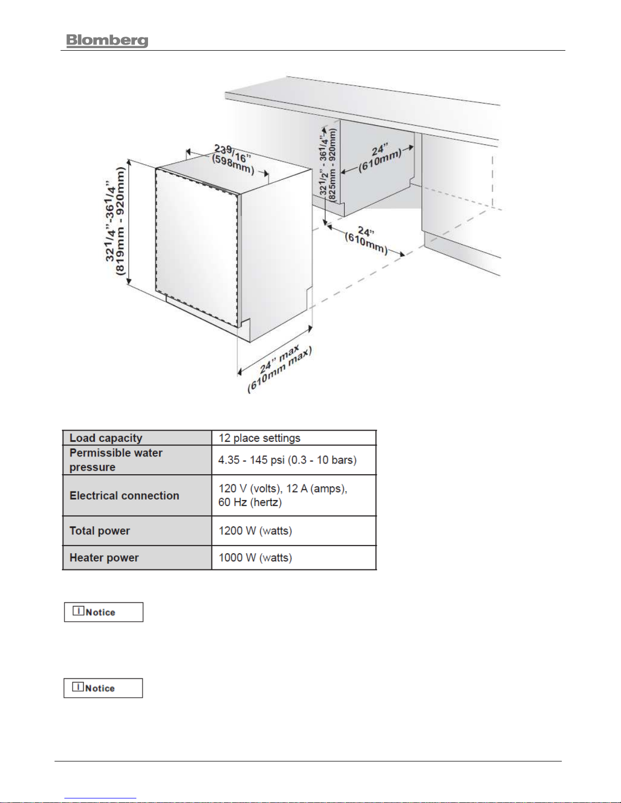
Packagıng & Dımensıons
Height (Cm) 82,0
Height Without Worktop (Cm) 82,0
Width (Cm) 59,8
Depth (Cm) 54,8
Depth, With Door Opened (Cm) 115,0
Height Adjustment (Cm) 10
Dımensıons Packed (Cm)
(Hxwxd)
85,9 X 64,4 X 66,1
Dımensıons Packed (İnch)
(Hxwxd)
33 7/8 X 25 3/16 X 26
Dımensıons Unpacked (İnch)
(Hxwxd)
32 1/4 X 23 9/16 X 21 5/8
Dımensıons Nıche (İnch)
(Hxwxd)
32 1/2 - 36 1/4 X 24 X 24
Net Weight(Kg) 38
Gross Weıght (Kg) 41
Weight - Packed (Lb) 83
Weight - Unpacked (Lb) 90
Packagıng Type Bu Standard
Depth - Packed (Cm) 66,1
Width - Packed (Cm) 64,4
Height - Packed (Cm) 85,9
Characteristics
Filter Plastic
Nr Of Spray Levels 3
Washing System Standard
Turbidity Sensor No
Drying System Static
Door Balance/Hinge Adjustment No
Column Mounting No
Adjustable Feet 4 Long & Extra Feet
Detergent Sample No
Salt Funnel No
Water Hardness Test Strip No
Performance
Energy Performance- Sales 322kwh/Year

BUILT- UNDER DISHWASHER
11 2011
Consumption
Washing Performance- Sales 70% / Not Written
Cleaning Performance 70% / Not Written
Drying Performance B
Water Consumption (Liters) 19,80
Energy Consumption (Kwh) 0,74
Program Duration (Min) 110
Insulation Us-L1
Noise Level - Db (A) - Iec 704 54
Design
Panel Blomberg Inlay 1a
Panel Color White
Inlay Color White
Panel Printing Text
Knob Color No
Buttons Color White
Embedded Handle White
Bar Type Handle No
Plinth Bı 82-92, Rear Feet Adjustable
Worktop No
Door Color White
Door Lego No
Decor Frame No
Side Panels Color White
Detergent Dispenser Albatros, Dark Grey Ral 7037
Indicators
Rinse Aid Indicator Yes
Salt Indicator No

BUILT- UNDER DISHWASHER
12 2011
Program, Controls
Range Ub104
Power On / Off Button
Nr Of Programs 4
Programme 1 Quick Wash
Programme 2 China Gentle
Programme 3 Regular Wash
Programme 4 Pots&Pans
Buttons Programme Start/Stop
Program Control Buttons
Screen No
Key Lock No
Program Sequence Yes 4 Leds
Count Down No
Half Load No
Delay Timer No
Rinse Aid İndicator Mechanical
Watertap Indicator No
Water Leakage Indicator No
Door Open Indicator No
Filter Clogged Indicator No
Reference Program Regula Wash
Program Follower No
Minimum Program Duration 30
Auto Programme No
Delicate Programme Yes
Express Programme No
Express Function No
Extra Drying Function No
Extra Quiet Function No
Hygiene Programme No
Intensive Programme Yes
Mix Programme No
Sensor No
Number Of Wash Temperatures 3
Bldc No

BUILT- UNDER DISHWASHER
13 2011
Racks / Baskets
Rack Color Albatross, Dark Grey 2 Ral 7037
Rack Type (Lower / Upper) Us2 Type
Accessory Color Dark Grey
Lower Rack Folding Tines Fixed
Lower Basket Folding Tines Fixed
Lower Rack Decorative Handle No
Lower Basket Decorative Handle No
Lower Rack Long Tool Basket No
Lower Basket Long Tool Basket No
Lower Rack Bottle Holder No
Lower Basket Bottle Holder No
Lower Rack Cutlery Basket Sliding Cutlery, Dark Grey 2 Ral 7037
Lower Rack Cutlery Basket
Separator
Yes
Upper Rack Decorative Handle Ph_Eu2_Dark Grey Ral 7037
Upper Basket Decorative Handle Yes
Upper Basket Mug Shelf Adjustable
Upper Rack Mug Shelf & Colour Yes, Dark Grey 2 Ral 7037
Upper Rack Number Of Shelfs 2
Upper Rack Adjustable Height Unloaded Adjustable
Upper Basket Adjustable Height Unloaded Adjustable
Upper Rack Glass Holder No
Glass Holder No
Upper Rack Folding Tines No
Upper Rack Multi-Purpose Tray No
3rd Basket No
Safety
Aqusafe/ Watersafe Yes
Aqusafe+/ Watersafe+ No
Waterstop System Watersafe
BUILT- UNDER DISHWASHER
14 2011
5. Installation Manual
Installation Manual For
Dishwasher Models
5.1. Important Safety Instructions
In addition to these instructions, the dishwasher shall be installed:
In accordance with all local codes or, in absence of a local code,
In the United States, with the National Electric Code,
In Canada, with the Canadian Electric Code C22.1-latest edition/Provincial and Municipal
codes and/or local codes
Read these installation instructions completely before installing and
follow them carefully. Save these installation instructions and pass them
on to any future user.
When installing the dishwasher, follow basic precautions, including the
following:
The dishwasher installation must be performed in accordance with this installation manual.
If you did not receive an installation manual, order it by calling 1-800-459-9848 or you may
also download it from our web site at www.blombergappliances.com
Installation and repair should be performed by a qualified installer. Work by unqualified
persons could be dangerous and may void the warranty.
Installation should be installed by an insured licensed plumber,
contractor or trained installer. Installation performed by persons other
than this could result in improper installation and property damage.
Do not operate the appliance if damaged, malfunctioning, partially disassembled or if it has
missing or broken parts.
Also follow the safety instructions of the user manual.
To reduce the risk of electric shock, fire, or injury to persons, the installer must ensure that
the dishwasher is completely enclosed at the time of installation.
Only connect the dishwasher to the power supply when all installation and plumbing work
is complete.
If the dishwasher is installed in a location that experiences freezing temperatures (e.g. in
a vacation home, cabin, etc.), you must drain all the water from the dishwasher’s interior.
Water system ruptures that occur as a result of freezing are not covered by warranty.
Dishwasher must be secured to adjacent cabinetry using the brackets provided. Failure to
do this may cause damage to property or bodily injury.
BUILT- UNDER DISHWASHER
15 2011
Connect to a properly rated, protected and sized power supply circuit to avoid electrical
overload. The dishwasher is designed for an electrical supply of 120 V (volts), 60 Hz
(hertz), AC, connected to a dishwasher-dedicated, properly grounded electrical circuit with
a fuse or breakers rated for 15 amperes. Electrical supply conductors shall be a minimum of
# 14 AWG copper wire rated at 75 °C (167 °F) or hig her. These requirements must be met
to prevent injury and machine damage. Consult a qualified electrician if in doubt.
Do not use any extension cord or portable outlet device to connect the dishwasher to a
power supply.
Ensure that any plastic wrappings, bags, small pieces etc. are disposed of safely and kept
out of the reach of children. Danger of suffocation!
Remove the door to the washing compartment when removing an old dishwasher from
service or discarding it. Ensure that the appliance presents no danger to children while
being stored for disposal.
Remove the door to the washing compartment when removing an old dishwasher from
service or discarding it. Ensure that the appliance presents no danger to children while
being stored for disposal.
The dishwasher drain hose must be installed with a drain loop at least 28”
(710mm) off the cabinet floor; otherwise the dishwasher may not drain
properly.
This dishwasher is intended for residential use only, and should not be
used in commercial establishments.
New installation - If the dishwasher is a new installation, most of the work
must be done before the dishwasher is moved into place.
Replacement - If the dishwasher is replacing another dishwasher, check
the existing dishwasher connections for compatibility with the new
dishwasher, and replace parts as necessary.
5.1.1. Inspect The Dishwasher
After unpacking the dishwasher and prior to installation, thoroughly inspect the dishwasher for
possible freight or cosmetic damage. Report any damage immediately.
Cosmetic defects must be reported within 10 days of installation.
Do not discard any bags or items that come with the original package
until after the entire installation has been completed.
5.1.2. How To Contact Us
You may either call our Toll Free Number at 1-800-459-9848 or contact us via the web site at
www.blombergappliances.com or Contact the Blomberg Distributor for your State or Province as
listed on the Distributor Contact List provided.
BUILT- UNDER DISHWASHER
16 2011
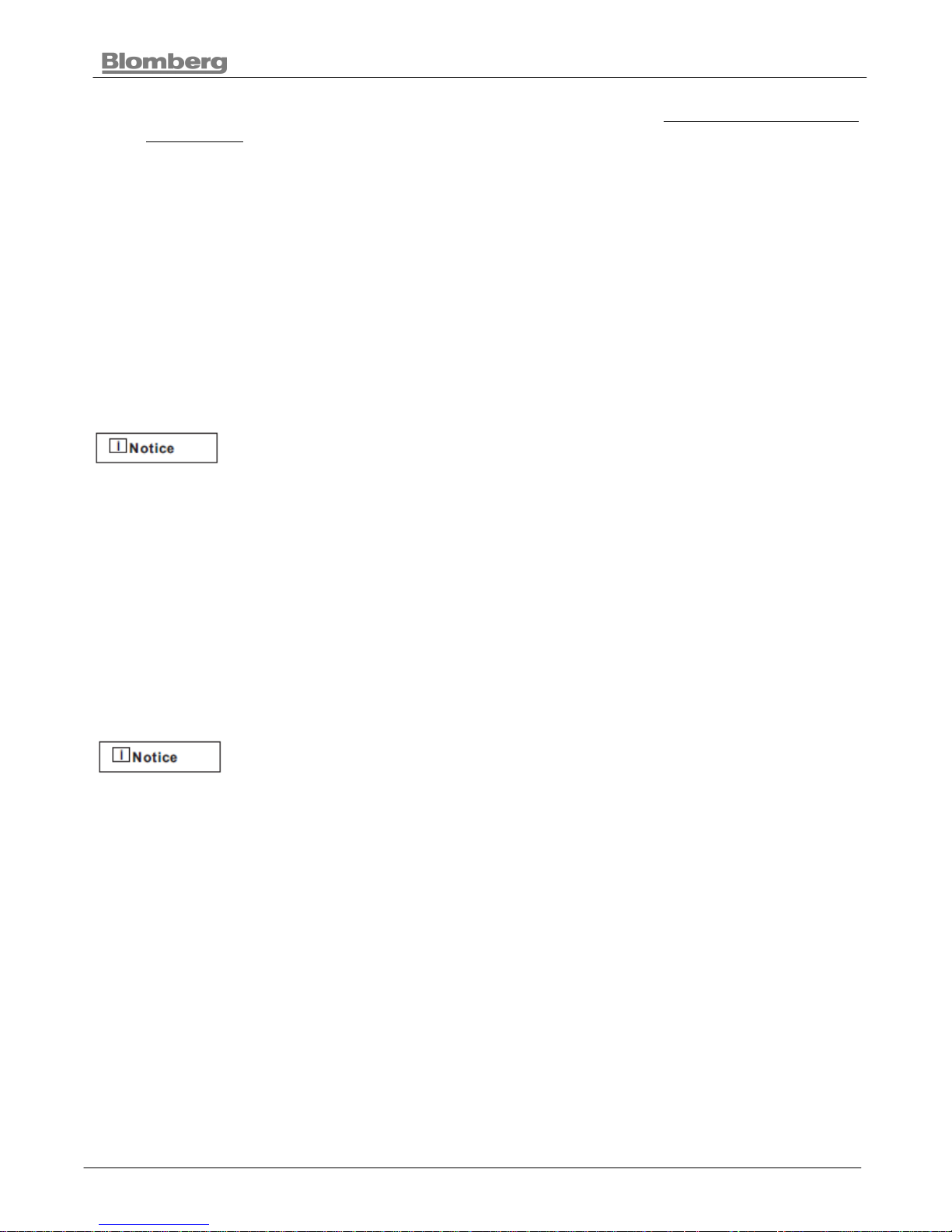
5.2. Tools Which May Be Needed
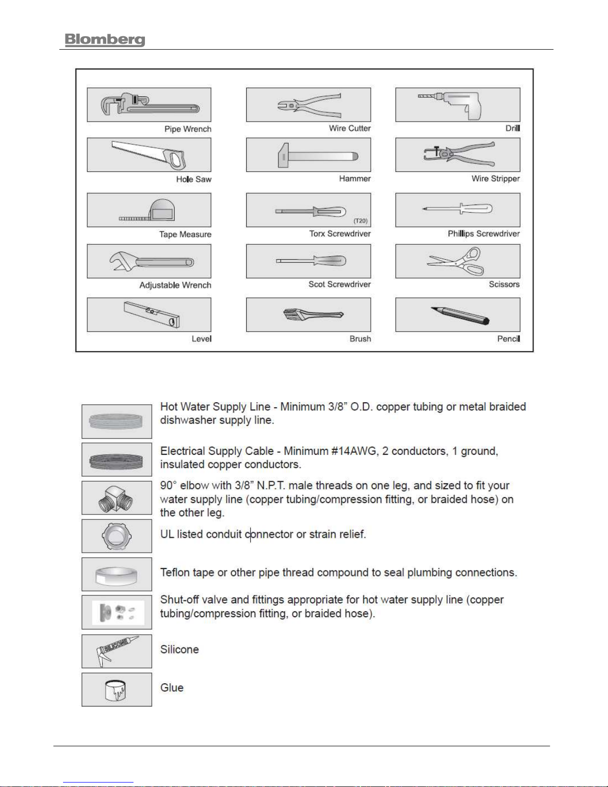
5.3. Materials Which May Be Needed
(Additional materials may be required to comply with local codes)
BUILT- UNDER DISHWASHER
17 2011
5.4. Materials Supplied
5.4.1. Parts Supplied
Parts for your dishwasher will come in several plastic bags. Check
your parts bags shown to make sure you have all the parts as listed
to the left.
5.4.2. Manual Bag
The dishwasher comes with a manual bag containing:
• User manual,
• Installation manual and
• Quick reference guide.
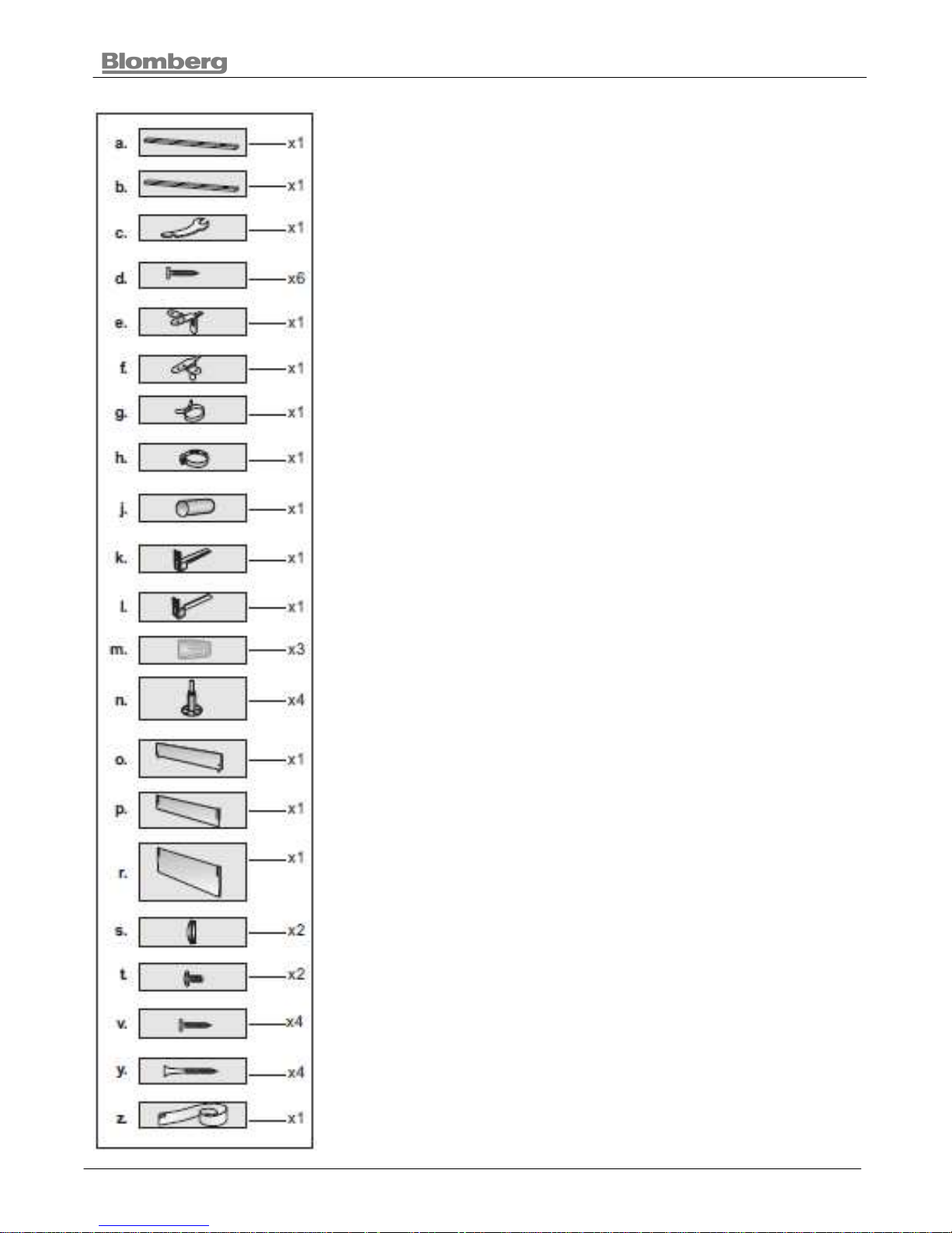
5.4.3. Dishwasher Parts Bag 1
This dishwasher bag comes with the following parts:
a. Side Trim Strips (Left)
b. Side Trim Strips (Right)
c. Adjusting Wrench
d. Screws Ø 1/8” x 5/8” (Ø 3.5mm x 14mm)
e. Mounting Bracket Left
f. Mounting Bracket Right
g. Spring Clamp
h. Screw Clamp
j. Rubber Connector
k. Toe Kick Bracket - Left
l. Toe Kick Bracket - Right
m. Wire Nuts
n. Long Legs
o. Toe Kick (toe kick without slots)
p. Toe Kick
r. Toe Kick
s. Plastic Caps
t. Screws Ø 3/16” x 1/4” (Ø 4mm x 6mm)
z. Steam Protection Foil
5.4.4. Dishwasher Parts Bag 2
In addition to the manual bag and the dishwasher parts bag 1 DW
34, DW 35 and DW 36 (dishwasher models which can accept a
wooden kitchen door) also come with a door panel installation kit
which contains:
v. Screws Ø 1/8” x 5/8” (Ø 3.5mm x 14mm)
y. Screws Ø 3/16” x 13/4” (Ø 4mm x 43mm)
5.4.5. Parts Attached To The Rear Of The Dishwasher
a. Side Trim Strips (Left)
b. Side Trim Strips (Right)
o. Toe Kick (toe kick without slots)
p. Toe Kick
r. Toe Kick
BUILT- UNDER DISHWASHER
18 2011
5.5. Dishwasher Specifications
5.6. Technical Features
Because we continually strive to improve our products, we may
changeour specifications and design without prior notice. This device
corresponds to the following directives: UL 749 Household Dishwasher
directive.
5.7. Enclosure Preparation
For proper dishwasher operation and appearance ensure that the
enclosure has the minimum dimensions shown in the figure above.
BUILT- UNDER DISHWASHER
19 2011
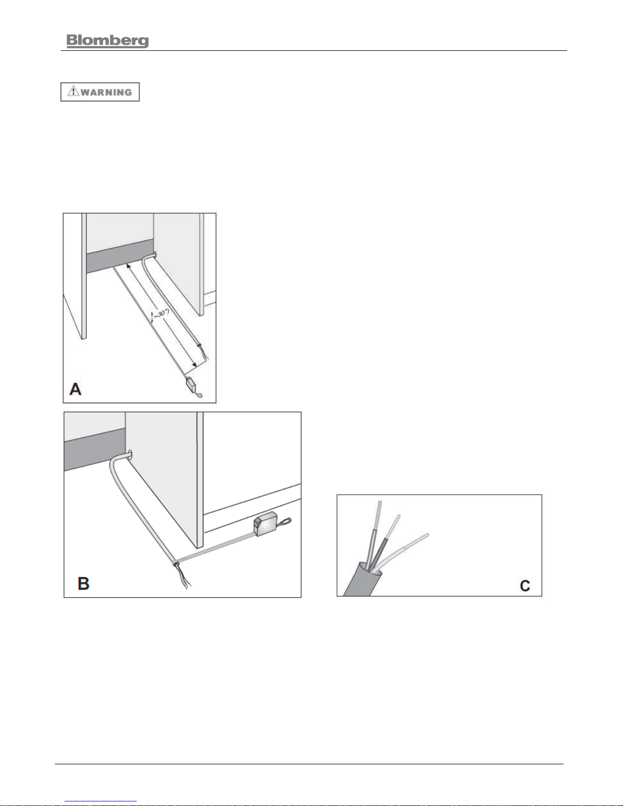
5.7.1. Electrical Preparation
To avoid electrical shock and/or a fire hazard, make sure electrical work is
properly installed. Only qualified electricians should perform electrical
work.
Before installation disconnect the power supply to the work area by unplugging the unit, “tripping”
the circuit breaker or removing the fuse.
The installer has the responsibility of ensuring that the dishwasher electrical installation is in
compliance with all national and local electrical codes and ordinances. The dishwasher is
designed for an electrical supply of 120 V, 60 Hz, AC, connected to a dishwasher-dedicated,
properly grounded electrical circuit with a fuse or breaker rated for 15 amperes.
Electrical supply cords must be a minimum #14AWG copper wire.
Position the cable extending approximately 30” (760mm) from the
enclosure’s back (Figure A).
To the right side position the cable extending Remove 2 15/16” - 315/16” (75mm-100mm)
approximately 5½” (140mm) (Figure B). of the cable’s outer casing, and then
remove 3/8” - 1/2” (9-13mm) of insulation
from each wire. (Figure C)
BUILT- UNDER DISHWASHER
20 2011
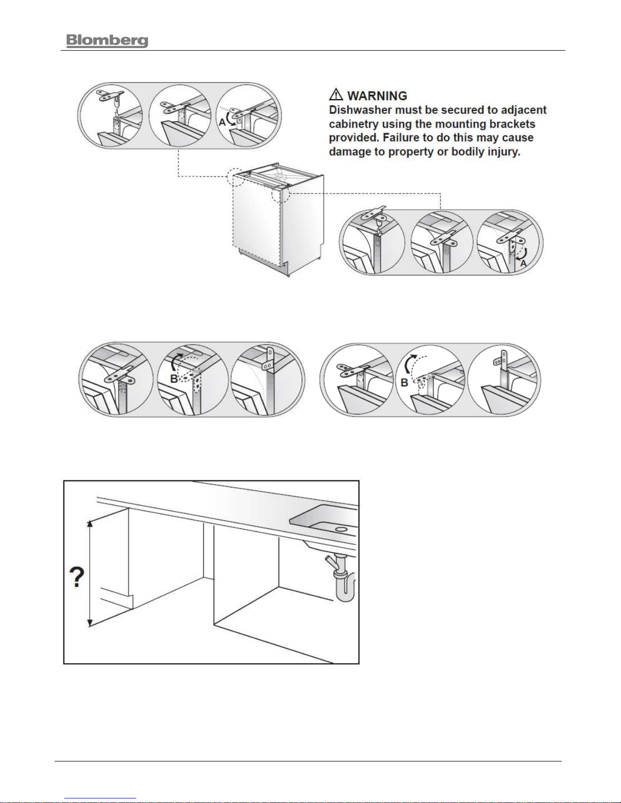
5.8. Preparation For Installing Mounting Brackets
Place the two mounting brackets into the top corners of the dishwasher.
Bend sides of mounting brackets (A) in order to fix from sides (if necessary).
5.9. Adjusting Height
Measure the height of the enclosure.
BUILT- UNDER DISHWASHER
21 2011
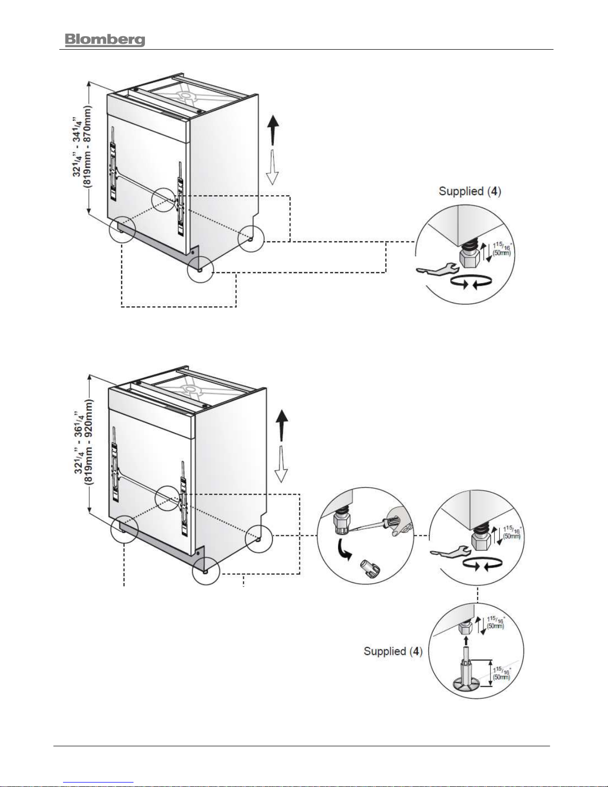
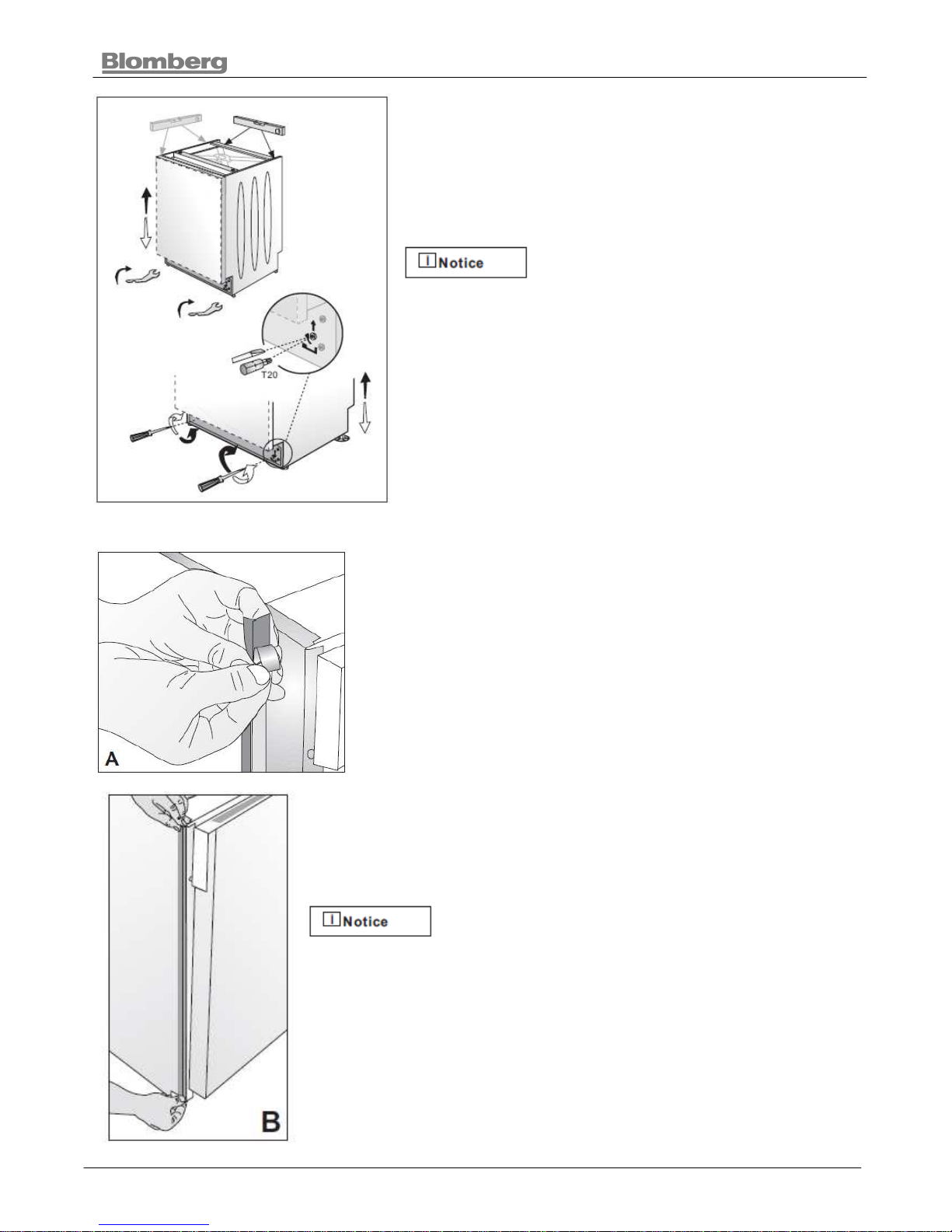
5.9.1. Installing The Foot Supports
If the height of the enclosure is 337/16” to 341/4” (850mm - 870mm) use short supports as shown
in the figure.
If the height of the enclosure is above 341/4”
(870mm) use long supports as shown in the figure.
BUILT- UNDER DISHWASHER
22 2011
Adjust the front foot level with the adjusting wrench to
balance and raise the dishwasher to the enclosure height.
Adjust the rear foot level with a screwdriver to balance and
raise the dishwasher to the enclosure height.
• Make sure the dishwasher is plumb and notice
dishwasher can be placed with a small clearance
under the counter top.
• Turning the screwdriver in the direction of the black
arrows will bring the dishwasher back feet up.
• Turning the screwdriver in the direction of the white
arrows will take the dishwasher rear feet down.
5.10. Installing The Side Trim Strips
Remove the adhesive tape (Figure A).
Place the trim strips on the front edge of the side walls (Figure B).
Make sure you use the correct trim strip since there is a left and
right side strip. The flexible material should be facing forward
(Figure B).
BUILT- UNDER DISHWASHER
23 2011
5.11. Preparing The Water Connection (A)
Install an easily accessible shut-off valve (not supplied) in the water supply line. All solder
connections must be made before the water line is connected to the dishwasher’s water inlet
valve. Water can also be supplied to the dishwasher by using a flexible braided hose line.
Check with your plumbing supply sources for the proper hose and 90° elbow and necessary
fittings for the water supply line. This material is not supplied, and must be purchased separately.
Installation should be performed by a qualified installer. Work by
unqualified persons could be dangerous and may void the warranty.
If the dishwasher is installed in a location that experiences freezing temperatures (e.g. in a
vacation home, cabin etc.), you must drain all the water from the dishwasher’s interior. Water
system ruptures that occur as a result of freezing are not covered by warranty.
5.11.1. Installing The 90° Elbow Fitting (B)
Do not over tighten the 90°
elbow. Doing so may
damage the water inlet valve and cause a
water leak.
If the water supply line is to be copper tubing,
make certain that the elbow has a compression
fitting. Apply Teflon tape or other pipe sealant
when required. Orient the water supply
connection downwards as shown in the figure so
the water line can be easily pulled underneath or
on the side of the dishwasher.
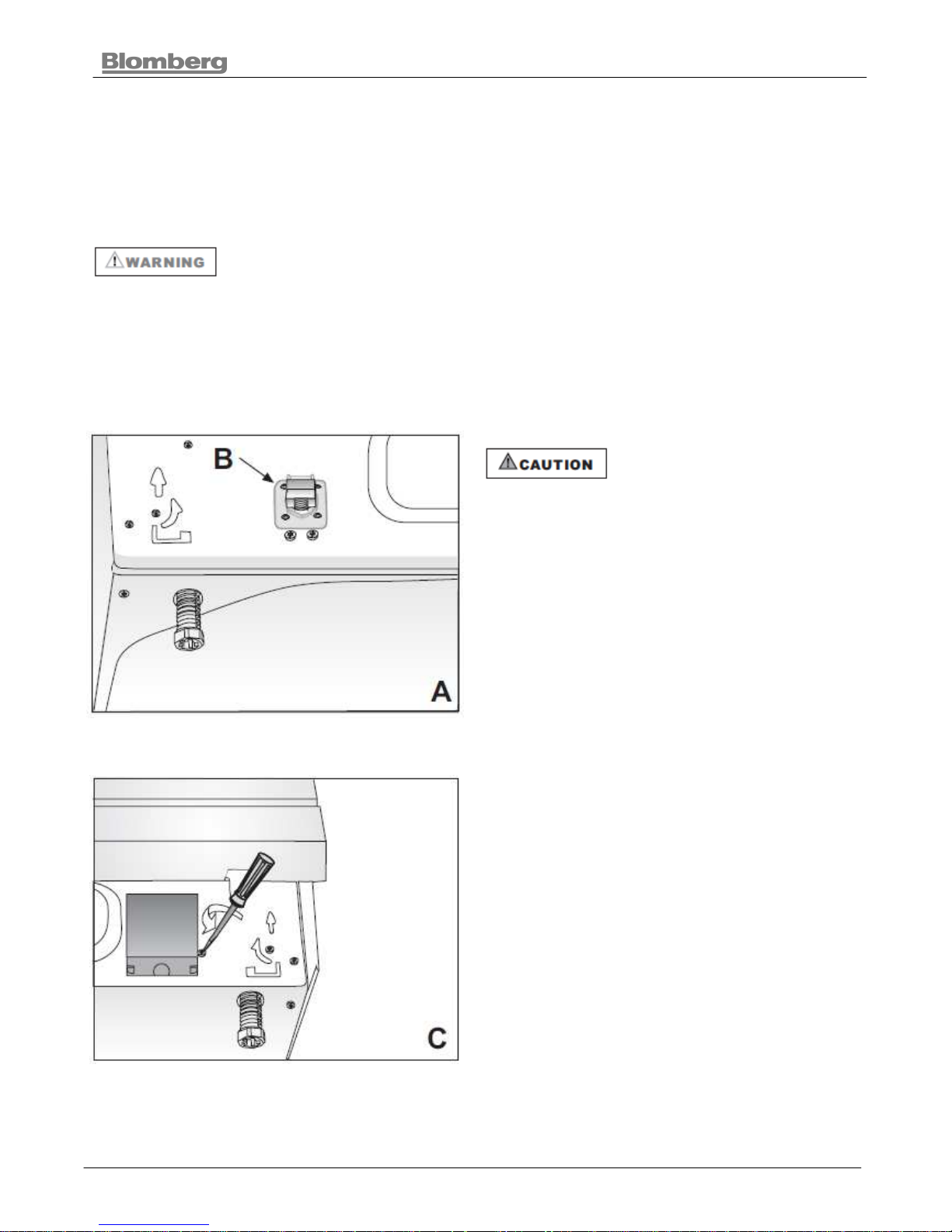
5.11.2. Junction Box Preparation (C)
Remove the junction box cover by removing the
screws as shown in the figure. They will be
reinstalled later.
BUILT- UNDER DISHWASHER
24 2011
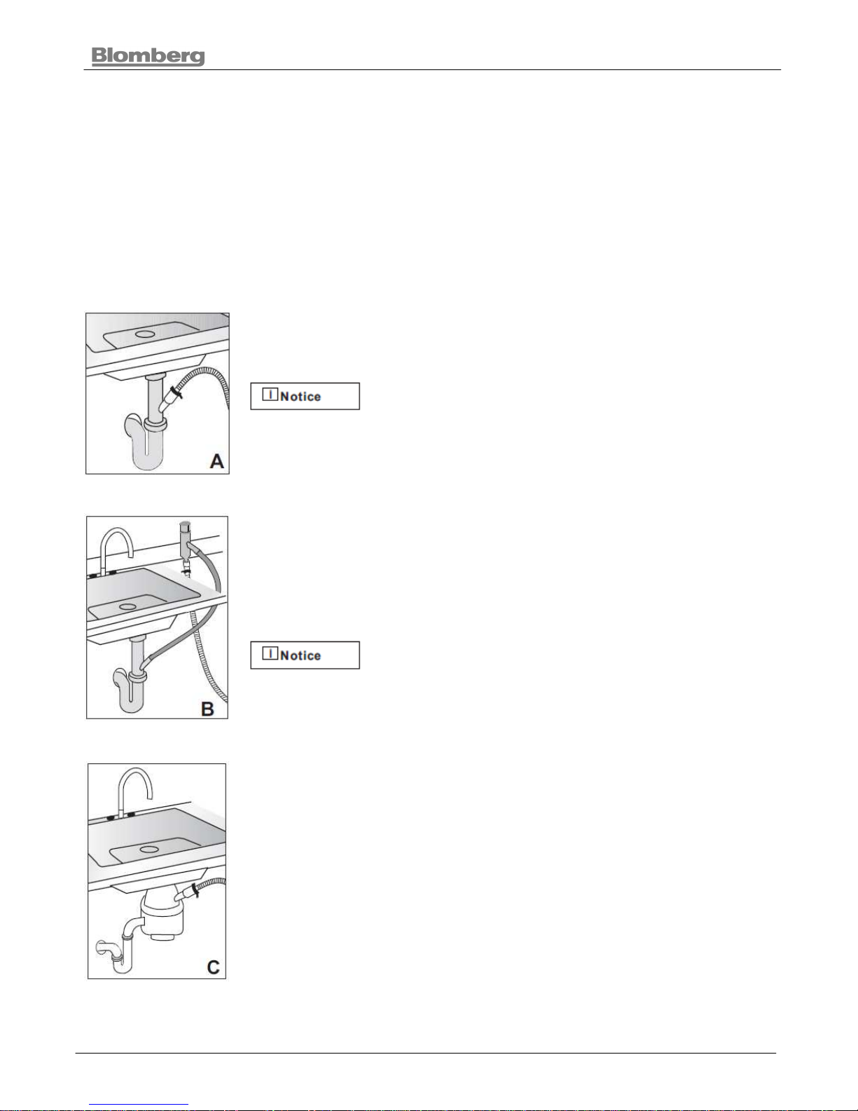
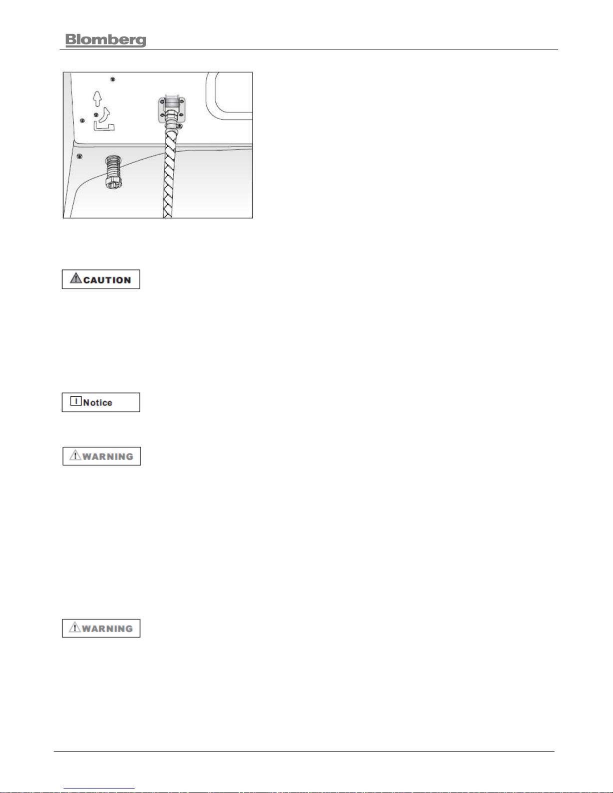
5.12. Drain Preparation
The dishwasher drain hose may be connected to the drain plumbing in one of three ways (Figure
A, B, C).
• Either one of the above methods must be used or the dishwasher will not operate properly.
• A hose that attaches to a sink spray can burst if it is installed on the same water line as the
dishwasher. If your sink has one, it is recommended that the hose be disconnected and the
hole plugged.
• The total length of the drain hose is 763/4” (1950mm). If a hose extension is required, a
drainage hose of equal quality must be used.
• The maximum length must not exceed 157 ½” (4000mm). Otherwise, the cleaning process
is negatively influenced.
5.12.1. Under The Sink Drain
Install a Y-branch tail pipe. (Figure A)
You must add a loop at least 28" (710mm) above the
floor of the cabinet and above the drain connection
in the drain hose to prevent waste water from not
draining properly, and causing either poor washing results or a bad
odor.
5.12.2. Installing An Air Gap
If the local ordinance requires an air gap (Figure B).
Check with local ordinance for type of air gap
required.
5.12.3. Disposal
Remove the drain connection plug before attaching the drain hose from the
dishwasher.
Every disposal has a hook up for a dishwasher; consult your disposer
manual for correct connection. (Figure C)
BUILT- UNDER DISHWASHER
25 2011
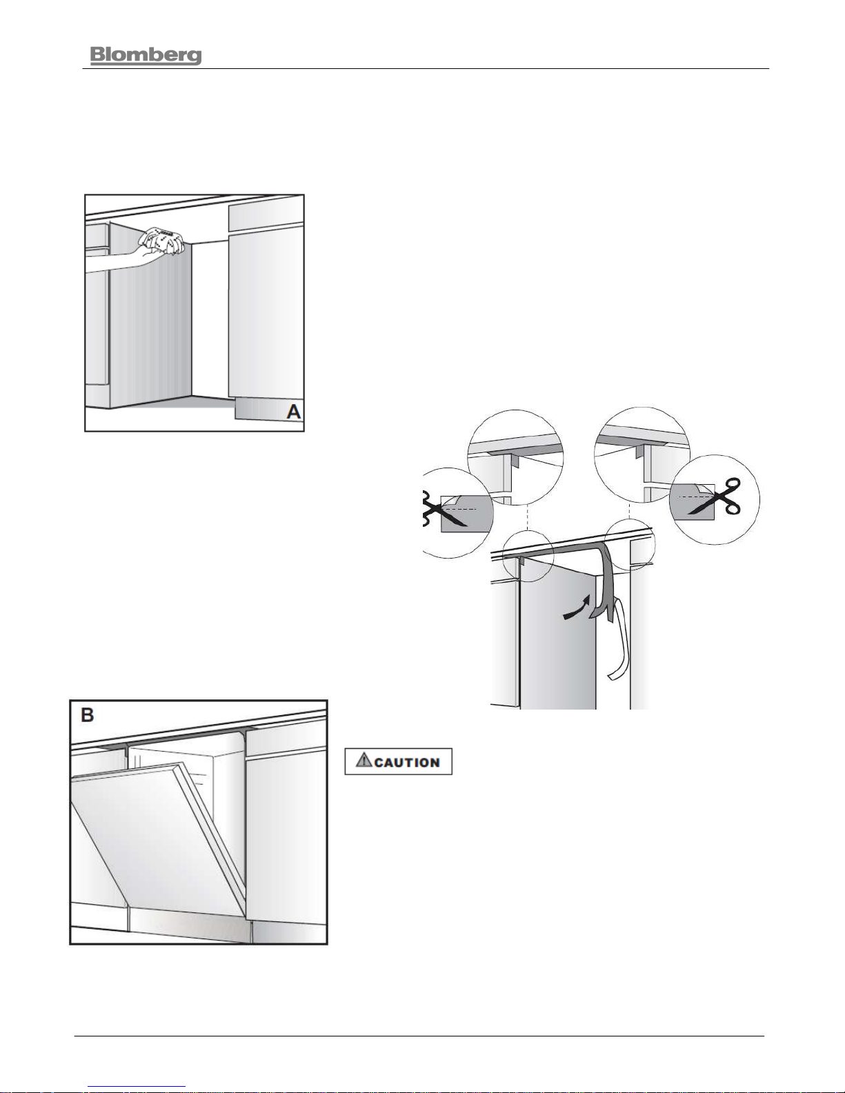
5.13. Steam Protection Foil
Steam will form inside the dishwasher during operation. At the end of the cycle, when the
dishwasher door is opened, it is required to use a steam protection foil to prevent any steam from
collecting on the underside of the counter top.
5.13.1. Fitting The Protection Foil
Before applying the steam protection foil to the underside of the
countertop, clean the area with a damp cloth (as shown in
Figure A). Once the area dries, apply the steam protection foil.
The steam protection foil will be applied at the
location where the hot steam escapes when
you first open the door (as shown in Figure B).
Steam protection foil must be applied
where the steam escapes when door is
first opened. Failure to install the steam protection foil
during installation can lead to damage to the cabinets
and countertop.
BUILT- UNDER DISHWASHER
26 2011
5.14. Placement Of Dishwasher Into The Opening
Make sure all hoses
and electrical wire
are pulled through the side opening
of the cabinet, no hoses are kinked
and all slack is taken out as shown
in the above figure.
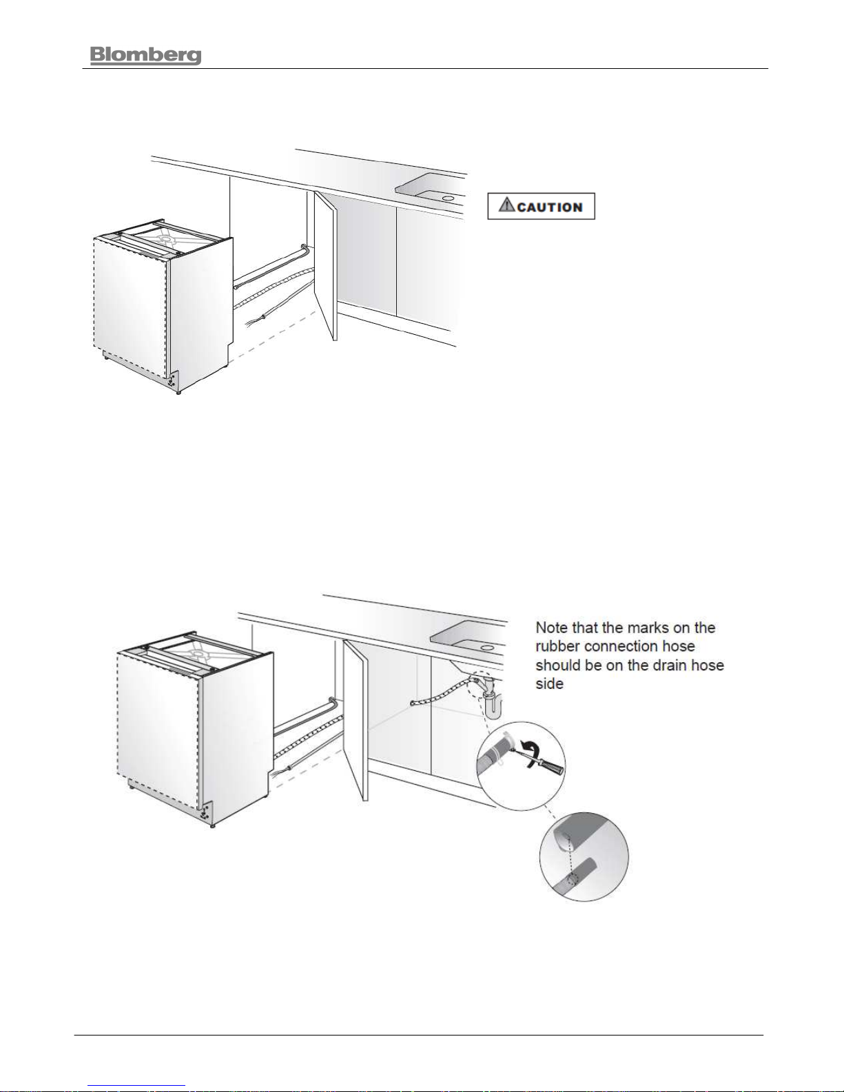
5.15. Drain Hose Connection, Water Supply & Electrical Connections
5.15.1. Drain Hose Connection
Connect the drain hose to the drain plumbing.
1. Use the supplied rubber connection hose and drain hose clamps to connect the dishwasher
drain hose to the plumbing drain connection.
2. Use the spring clamp to secure the rubber connection hose to the dishwasher drain hose. Use
the screw clamp to secure the rubber connection hose to the plumbing drain connection.
BUILT- UNDER DISHWASHER
27 2011
5.15.2. Water Supply Connection
Water supply may be connected to the dishwasher in one
of two ways:
• With metal braided hose.
• With copper tubing.
5.15.3. Braided Hose/Copper Tubing
After connections are made turn on the water supply to check for leaks.
• Hot water supply line: Use minimum 3/8” O.D. copper tubing or metal
braided dishwasher supply line.
• Temperatures required for soldering and sweating will damage the dishwasher’s water
inlet valve so if any such operation is needed, keep the heat source min. 77/8” (200mm)
away from the dishwasher’s water inlet valve.
• There should not be any sharp bends in the water line that may restrict the water flow.
• Teflon tape or pipe tread compound must be used for sealing the connection. Before
connecting the copper water supply line to the dishwasher, flush it with hot water to clear
any foreign material.
After connections are made turn on the water supply to check for leaks.
5.16. Electrical Connection
• Make sure the voltage and frequency listed on the data plate correspond
with the household electrical supply. This data must correspond to
prevent injury and machine damage. Consult a qualified electrician if in doubt.
• Only connect the dishwasher to the mains when all installation and plumbing work is
complete.
• Do not use any extension cord or portable outlet device to connect the dishwasher to a
power supply.
5.16.1. Grounding Instructions
This appliance must be grounded. In the event of a malfunction or breakdown, grounding will
reduce the risk of electric shock by providing a path of least resistance for electric current. This
appliance must be installed and grounded in accordance with all local codes and ordinances.
Improper connection of the equipment-grounding conductor can result in
a risk of electric shock. Check with a qualified electrician or service
representative if you are in doubt whether the appliance is properly grounded.

BUILT- UNDER DISHWASHER
28 2011
Install a strain relief (not supplied) into the opening on the kick
plate. (Figure A)
Pass the electrical supply cable through the strain relief; make
sure the strain relief clamps the insulated outer casing of your
electrical supply cord and not the wires themselves. Leave
215/16” “ to 315/16” “ (75mm / 100mm) of insulated wire
extending through the strain relief (Figure B). Tighten the strain
relief screws. (Make sure you can not pull the electrical cord out)
of the strain relief.
Do not pre-twist the wires before connecting them with wire
nuts.
Using the supplied wire nuts, connect the electrical supply wires
to the dishwasher’s wires, black to black, white to white, and
green or bare to green or bare. Make certain that the insulated
wires show no bare wire from the bottoms of the wire nuts.
Gently tug the wires to make certain they are securely
connected (Figure C).
5.16.2. Fasten Junction Box
1. Pull the wires into the junction box. Be sure that the wire
nuts do not loosen.
2. Replace the cover on the junction box.
3. Secure the cover with the screws (Figure D).
BUILT- UNDER DISHWASHER
29 2011
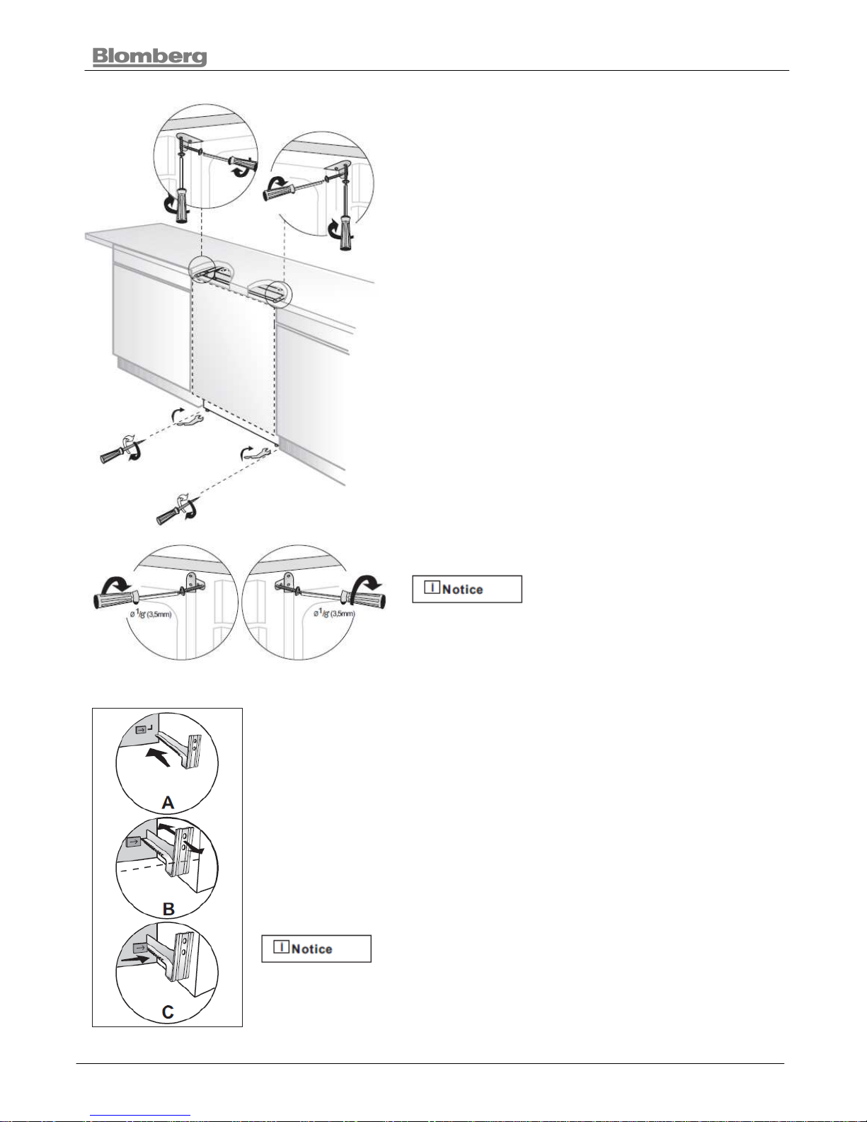
5.17. Readjusting Foot Levels
Now that the dishwasher is in the cabinet you must
readjust the feet to bring the dishwasher up to the
required height and attach it underneath the
countertop.
1. Readjust the front foot levels with adjusting wrench
to balance the dishwasher and raise it up under the
countertop, make sure the unit is level.
2. Readjust the rear foot levels with a screwdriver to
balance the dishwasher and raise it to the required
height using the brackets supplied.
3. Attach the dishwasher underneath the countertop
with the four screws supplied (Ø 1/8” x 1/8” - Ø 3.5mm
x 14mm). Make sure you do not go through the top of
the countertop or damage granite.
For models, note that you
should keep the total height of
the dishwasher at 321/4” (819mm) max.
5.18. Adjusting The Movable Toe Kick
Now that you have successfully installed the dishwasher, you need to
attach the toe kick to the dishwasher. The two piece toe kick can be
adjusted to the height and depth needed for your kitchen. Be sure to use
the slotted toe kick in the front and the other behind it. They slide into
each other.
1. Insert the movable toe kick brackets into the channel (A).
2. Make sure that the plastic tab to the left of the “L” opening on the
dishwasher has not closed the channel you will push the bracket through.
Be sure to notice there is a left and a right bracket.
Adjust the toe kick brackets forward or backwards
so that they will align with the kitchen toe kick (B).

BUILT- UNDER DISHWASHER
30 2011
Lock the toe kick brackets as shown with the plastic tab in the
figure C by pushing the plastic tab on the dishwasher into the teeth
of the bracket (C).
3. Now attach the toe kick to the bracket with the two (Ø 3/16” x
1/4” - Ø 4mm x 6mm) screws and the caps provided as follows.
If the enclosure height is below 331/16” (840mm) use only “o”
labelled toe kick (toe kick without slots). Installation should be done
following the steps illustrated in the Figures A, B and C
respectively.
1. Bend tabs on toe kick (o) inwards (A).
2. Secure toe kick to brackets with screws (t) as shown in the
supply bags (B).
3. Attach caps (s) as shown in the supply bags (C).
If the enclosure height is above 331/16” (840mm) use “o” and “p”
labelled toe kicks together. Make sure the slotted toe kick “p” is on
the outside so you can adjust height of the toe kick. Installation
should be done following the steps illustrated in the figures A, B
and C respectively.
1. Align the toe kick (o) and (p) (A).
2. Secure toe kicks to brackets with screws (t) after adjusting the
height of the slotted toe kick (p) (B).
3. Attach caps (s) as shown in the supply bags (C).
If the enclosure height is above 341/4” (870mm) use “o” and “r”
labelled toe kicks together. Make sure the slotted toe kick “r” is on
the outside so you can adjust height of the toe kick. Installation
should be done following the steps illustrated in the figures A, B
and C respectively.
1. Align the toe kick (o) and (r) (A).
2. Secure toe kicks to brackets with screws (r) after adjusting the
height of the slotted toe kick (t) (B).
3. Attach caps (s) as shown in the supply bags (C).
5.19. Installing The Outer Door
Measure the height and width of the enclosure (Figure A)
and the toe kick. Determine how big the wooden door can
be. For example if the height is 337/8” (860mm) and if the
toe kick is 315/16” (100mm) the door can not be taller than
2915/16” (760mm).
1. Prepare the wooden door with the mounting brackets.
Height : Height of the wooden door 28” (711mm)
Width : 23 ¼” to 23 ½” (592mm - 595mm)
Thickness : ¾ “ (19mm)
 Loading...