

Page 1

MARK V
ELECTRIC CONVECTION OVEN
INSTALLATION OPERATION MAINTENANCE
BLODGETT OVEN COMPANY
www.blodgett.com
44 Lakeside Avenue, Burlington, Vermont 05401 USA Telephone: (802) 658-6600 Fax: (802)864-0183
PN 33101 Rev K (3/14)
© 2014 G.S. Blodgett Corporation
Page 2

Your Service Agency’s Address:
Model
Serial number
Oven installed by
Installation checked by
Page 3

IMPORTANT
TABLE OF CONTENTS
WARNING: Improper installation, adjustment, alternation,
service or maintenance can
cause property damage, injury or death. Read the instllation, operation and maintenance instructions thoroughly
before installing or servicing
this equipment.
FOR YOUR SAFETY
Do not store or use gasoline or
other ammable vapors or liquids in the vicinity of this or any
other appliance.
The information contained in this
manual is important for the proper installation, use, and maintenance of this oven. Adherence
to these procedures and instructions will result in satisfactory
baking results and long, trouble
free service. Please read this
manual carefully and retain it for
future reference.
ERRORS: Descriptive, typographic or pictorial errors are
subject to correction. Specications are subject to change without notice.
INSTALLATION
Oven Description and Specications ....................................... 2
Delivery and Location .................................................... 3
Utility Connections Standards and Codes .................................. 4
Electrical Connection ..................................................... 5
Oven Assembly and Startup ............................................... 6
OPERATION
IQ VVC-208 Control ...................................................... 8
Component Description ............................................... 8
Operational Test Procedure ........................................... 9
Recipe Review ....................................................... 9
View Temperature Setting ............................................. 9
Cool Down........................................................... 9
Setback ............................................................ 10
Programming ....................................................... 10
Changing the Menu Strip ............................................. 10
Recipe Programming (1724) ......................................... 11
System Programming (6647) ......................................... 16
Product or Alarm Name Library (6647) ................................ 19
SCK Address (6647) ................................................. 21
Blodgett IQ™ Phase IV Control ........................................... 22
Component Description .............................................. 22
Oven Operation Startup: ............................................. 23
Programming Single Stage Recipes ................................... 25
Programming Multiple Stage Recipes ................................. 27
2ND Level Programming ............................................. 30
Programming the Offset .............................................. 31
Replacing the Recipe Card ........................................... 31
MAINTENANCE
Cleaning and Preventative Maintenance .................................. 32
Page 4

Installation
Oven Description and Specications
Cooking in a convection oven differs from cooking in a
conventional deck or range oven since heated air is constantly recirculated over the product by a fan in an enclosed chamber. The moving air continually strips away
the layer of cool air surrounding the product, quickly allowing the heat to penetrate. The result is a high qual-
ity product, cooked at a lower temperature in a shorter
amount of time.
ELECTRICAL RATINGS PER SECTION
VOLTAGE
U.S. and Canadian installations
208 60 11.0 1 51 — 51 — 6 AWG
208 60 11.0 3 31 29 29 — 8 AWG
220-240 60 11.0 1 44 — 44 — 6 AWG
220-240 60 11.0 3 26 24 24 — 8 AWG
440 60 11.0 3 15 14 14 — 12 AWG
480 60 11.0 3 14 13 13 — 12 AWG
General Export installations
208 50 11.0 3 18 18 18 4 Size per local code
220-240 50 11.0 1 48 — — 48 Size per local code
220/380 50 11.0 3 18 16 16 2 Size per local code
240/415 50 11.0 3 18 14 14 4 Size per local code
230/400 50 11.0 3 18 15 15 3 Size per local code
HZ
KW
PHASE
L1 L2 L3 N
Blodgett convection ovens represent the latest advancement in energy efciency, reliability, and ease of operation. Heat normally lost, is recirculated within the cooking
chamber before being vented from the oven: resulting in
substantial reductions in energy consumption and enhanced oven performance.
MAX LOAD (AMPS)
MOTOR
NOTE: Electrical connection wiring is sized for 90°C copper wire at 125% of rated input.
2
Page 5

Installation
Delivery and Location
DELIVERY AND INSPECTION
All Blodgett ovens are shipped in containers to prevent
damage. Upon delivery of your new oven:
• Inspect the shipping container for external damage.
Any evidence of damage should be noted on the
delivery receipt which must be signed by the driver.
• Uncrate the oven and check for internal damage.
Carriers will accept claims for concealed damage if
notied within fteen days of delivery and the shipping container is retained for inspection.
The Blodgett Oven Company cannot assume responsibility for loss or damage suffered in transit. The carrier assumed full responsibility for delivery in good order when
the shipment was accepted. We are, however, prepared
to assist you if ling a claim is necessary.
OVEN LOCATION
The well planned and proper placement of your oven will
result in long term operator convenience and satisfactory
performance.
The following clearances must be maintained between
the oven and any combustible or non-combustible construction.
• Oven body right side 1/2” (1.3cm)
It is essential that an adequate air supply to the oven be
maintained to provide a sufcient ow of combustion and
ventilation air.
• Place the oven in an area that is free of drafts.
• Keep the oven area free and clear of all combus-
tibles such as paper, cardboard, and ammable
liquids and solvents.
• Do not place the oven on a curb base or seal to
a wall. This will restrict the ow of air and prevent
proper ventilation. Tripping of the blower motor’s
thermal overload device is caused by an excessive
ambient temperature at the back of the oven. This
condition must be corrected to prevent permanent
damage to the oven.
• The location must provide adequate clearance for
the air opening into the combustion chamber.
Before making any utility connections to this oven, check
the rating plate to be sure the oven specications are
compatible with the gas and electrical services supplied
for the oven.
1. Pull out control panel. The rating plate attached to the
inside of the control compartment.
• Oven body left side 1/2” (1.3cm)
• Oven body back 1/2” (1.3cm)
• Oven body bottom 1/2” (1.3cm)
The following clearances must be available for servicing.
• Oven body sides 12” (30cm)
• Oven body back 12” (30cm)
3
Page 6

Installation
Utility Connections Standards and Codes
THE INSTALLATION INSTRUCTIONS CONTAINED
HEREIN ARE FOR THE USE OF QUALIFIED INSTALLATION AND SERVICE PERSONNEL ONLY. INSTALLATION OR SERVICE BY OTHER THAN QUALIFIED
PERSONNEL MAY RESULT IN DAMAGE TO THE OVEN
AND/OR INJURY TO THE OPERATOR.
Qualied installation personnel are individuals, a rm,
a corporation, or a company which either in person or
through a representative are engaged in, and responsible
for:
• the installation of electrical wiring from the electric
meter, main control box or service outlet to the electric appliance.
Qualied installation personnel must be experienced in
such work, familiar with all precautions required, and have
complied with all requirements of state or local authorities
having jurisdiction.
U.S. and Canadian installations
All ovens, when installed, must be electrically grounded
in accordance with local codes, or in the absence of local codes, with the National Electrical code, ANSI/NFPA
7o-Latest Edition and/or canadian National Electric code
c22.2 as applicable.
The ventilation of this oven should be in accordance with
local codes. In the absence of local codes, refer to the
National ventilation code titled, “Standard for the Installa-
tion of Equipment for the Removal of Smoke and Grease
Laden Vapors from commercial cooking Equipment”, NF-
PA-96-Latest Edition.
General export installations
Installation must conform with Local and National instal-
lation standards. Local installation codes and/or requirements may vary. If you have any questions regarding the
proper installation and/or operation of your Blodgett oven,
please contact your local distributor. If you do not have a
local distributor, please call the Blodgett Oven Company
at 0011-802-860-3700.
4
Page 7
Ovens are supplied for operation on several different voltages with single or three phase grounded circuits. The
electric motor (single or two speed), heating elements,
oven lights, indicator lights and related switches are connected by one power supply to the oven. Before making
any electrical connections to this unit, check the oven
rating plate located on the underside of the upper ledge
above the right hand door. Be sure the proper electrical
supply is connected to the oven.
All ovens, when installed, must be electrically grounded
in accordance with local codes or in the absence of local codes, with the National Electrical Code, ANSI/NFPA
70-Latest Edition and/or Canadian Electrical Code CSA
C22.1 as applicable.
Wiring diagrams are located on the control compartment
cover and at the back of the oven.
WARNING!!
In order to prevent damage, there is no power
to the heating elements unless the blower is
operating.
U.S. and Canadian Installations
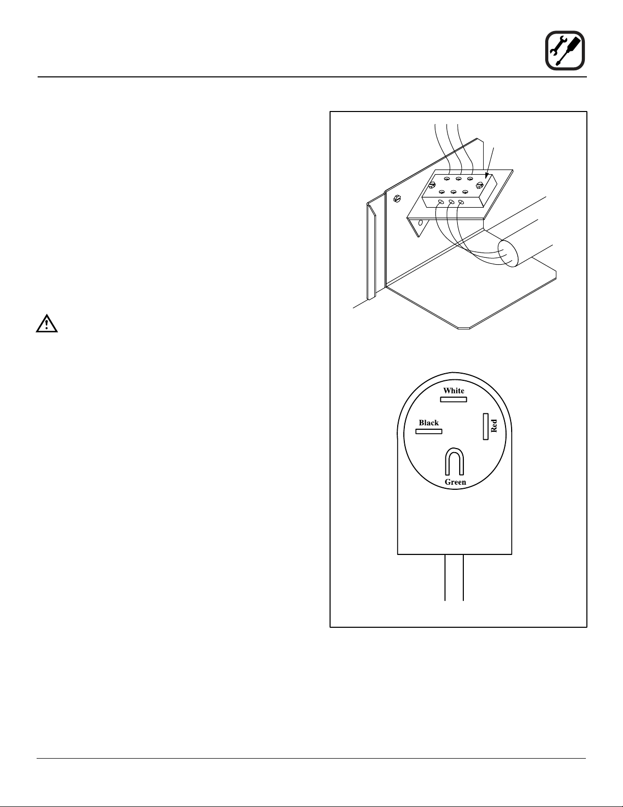
For Single Phase Installations:
1. Connect the supply conduit to the wire duct located
in the lower left hand corner as viewed from the rear
of the oven.
Installation
Electrical Connection
Terminal Block
Single Phase Installations
2. Run the supply wires through the wire duct to the
front of the oven. Connect the wires to the terminal
block located at the lower right front corner.
NOTE: Remove the bottom trim and control com-
partment covers to access the terminal
block. Slide the control module forward for
easy connections.
For Three Phase Installations:
These units are supplied with a power cord and a 15-50P
NEMA plug (4 prong grounding 50 amp 250 volt). It is intended for use with a 15-50R NEMA receptacle.
Export Installations
Export ovens are not supplied with a power cord. Size
the electrical connection in accordance with local and National installation standards.
Three Phase Installations
Figure 1
5
Page 8
Installation
Oven Assembly and Startup
Check that all of the components for your oven conguration were received. In addition to the oven itself, legs or
other accessories may be required.
NOTE: In MARK V series ovens the legs are packed in
the oven.
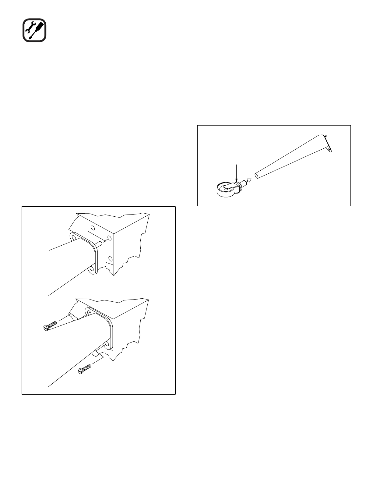
LEG AND CASTERS
1. With the oven lying on it’s back, align the threaded
stud in each leg with the nut located inside each bottom front corner of the oven frame. Turn the legs
clockwise and tighten to the nearest full turn.
2. Align the two leg plate holes in each leg with those
in the oven bottom and secure the leg using two 1/2”
bolts.
NOTE: For bolts on front and back edge of oven,
hand tighten only. They will need to be removed for shelf installation.
3. Slide the caster assemblies into the bottom of each
leg. Hand tighten the two set screws on the side of
each caster.
NOTE: Two casters with locking devices must be in-
stalled on the front of the oven. casters without locking devices must be installed at the
rear of the oven.
Adjustment Collar
Figure 3
4. Carefully tip the oven up on the newly installed legs
and casters.
Figure 2
5. Place a level on top of the oven. Loosen the set
screws on the side of each caster. Turn the adjustment collar clockwise to raise and counter clockwise
to lower the oven.
6. When the oven is level, tighten the casters by turning
the two set screws on the side of each caster assembly.
NOTE: When casters are used in conjunction with
a power supply cord for movable appli-
ances, a xed restraint should be provided.
This restraint should secure the oven to a
non-movable surface to eliminate stress on
the connector. If the oven is moved from its
regular location, the restraint must be reconnected when the oven is returned.
6
Page 9
Installation
Oven Assembly and Startup
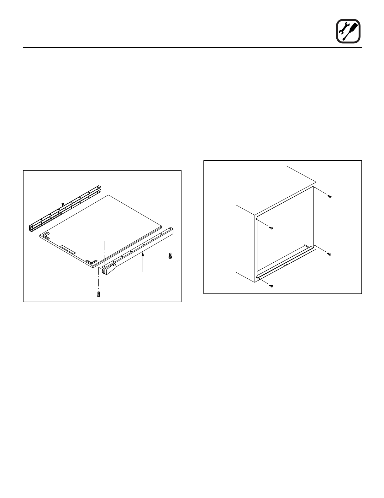
SHELF INSTALLATION
1. Remove the 4 leg mounting bolts from the front and
back edge of the oven.
2. Line the front and back holes of the right channel assembly with the leg mounting bolt holes on the right
side of the oven.
3. Secure using the leg mounting bolts.
4. Repeat steps 2-3 for the left channel assembly.
5. Slide the shelf into the track in the channel assemblies.
Left Channel
Assembly
Back of
Oven
Shelf Assembly
NSF BOLTS
These bolts are required by NSF to block any exposed
hole on the back of an oven. This includes:
• any unit, single or stacked, without a back panel.
• any holes in stacked units not used for mounting
stacking brackets.
1. Locate the 5/16” bolts that were shipped with the
oven.
2. Install the bolts as shown.
Front of
Oven
Figure 4
Right Channel
Assembly
Units without back panels
Figure 5
INITIAL STARTUP
Each oven, and its component parts, have been thoroughly tested and inspected prior to shipment. However, it is
often necessary to further test or adjust the oven as part
of a normal and proper installation. These adjustments
are the responsibility of the installer, or dealer. Because
these adjustments are not considered defects in material or workmanship, they are not covered by the Original
Equipment Warranty. They include, but are not limited to:
calibration of the thermostat, adjustment of the doors, leveling, and tightening of fasteners. No installation should
be considered complete without proper inspection, and if
necessary, adjustment by qualied installation or service
personnel.
7
Page 10
Operation
IQ VVC-208 Control
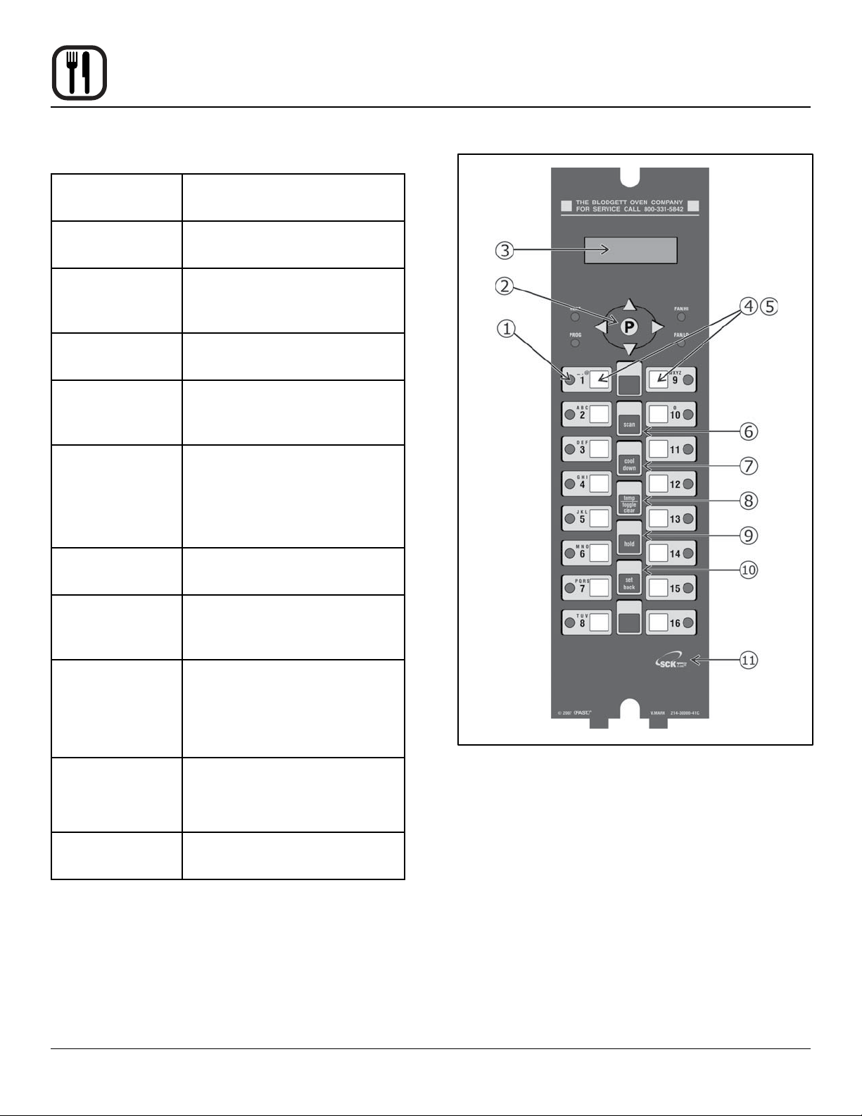
COMPONENT DESCRIPTION
1. Indicator
Lights
2. Programming
Buttons
3. VFD (Vacuum Fluorescent Display)
4. Slide-In
Menu Strips
5. Product
Buttons
6. SCAN key Used for recipe review during
7. COOL
DOWN key
Light up when product key is
activated
Used to access programming
mode and change parameters
Bright blue for easy viewing.
Displays programming and cook
cycle information
Menu items are printed directly
on easy-to-change menu strip
Used to activate cook cycles
and for certain programming
functions
idle.
Used to review time remaining
during multiple cooks (press &
hold)
Used to enter or exit cool down
mode
8. TEMP/
TOGGLE
CLEAR key
9. HOLD key Holds are not used for RFC
10. SETBACK
key
11. SCK LINK
logo
Used to check actual temperature; also used to clear value
when in programming mode
applications. Used to toggle
between upper and lower case
letters when programming
libraries
Used to enter or exit Setback
mode
Signies your control is communications capable
Figure 6
8
Page 11

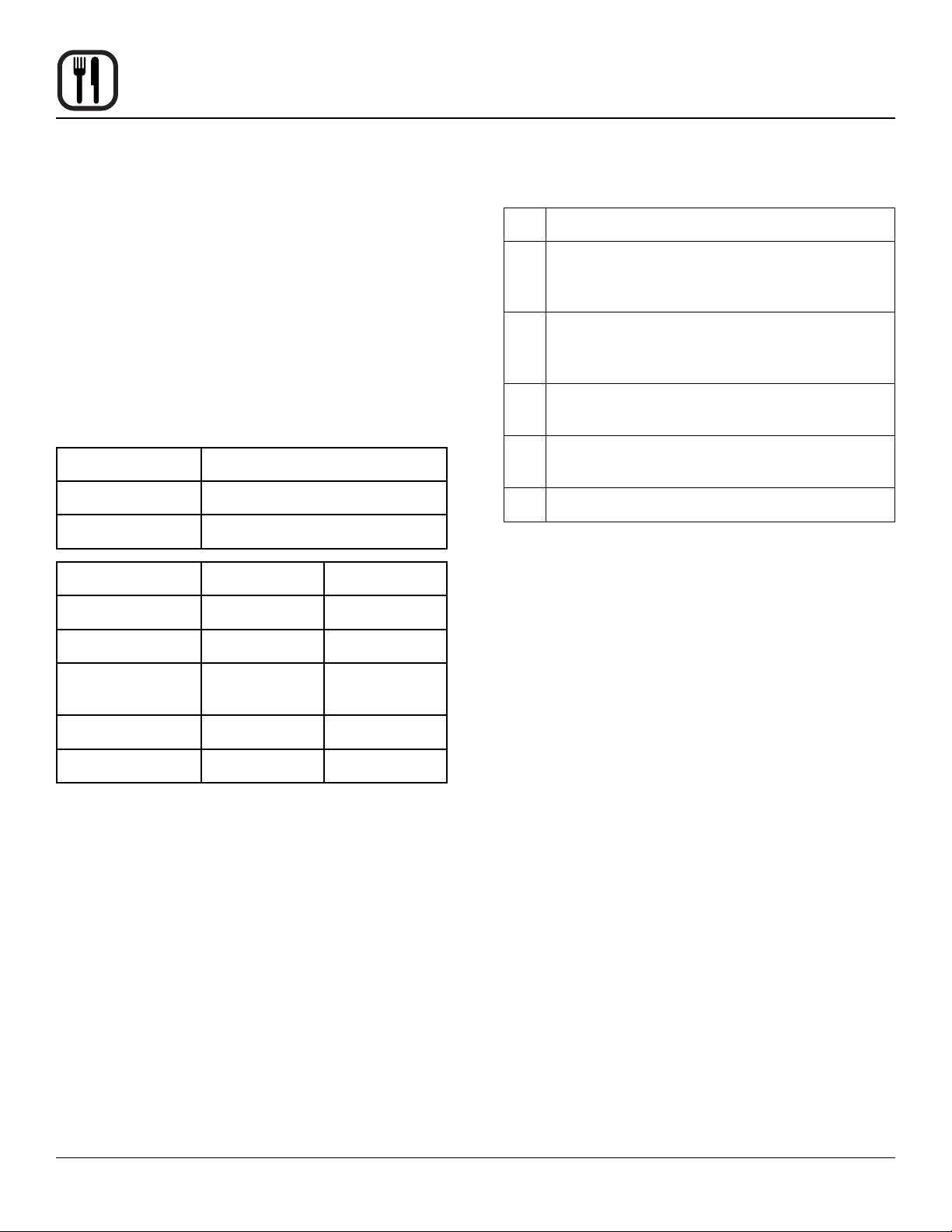
OPERATIONAL TEST PROCEDURE
Operation
IQ VVC-208 Control
1
2
3
4
5
6
RECIPE REVIEW
Quickly see what is programmed for each product key.
1. Press the SCAN key.
2. Select any product key previously programmed-LED
will be lit above the key.
3. Press the DOWN arrow key to scroll through the list.
4. Press SCAN to exit.
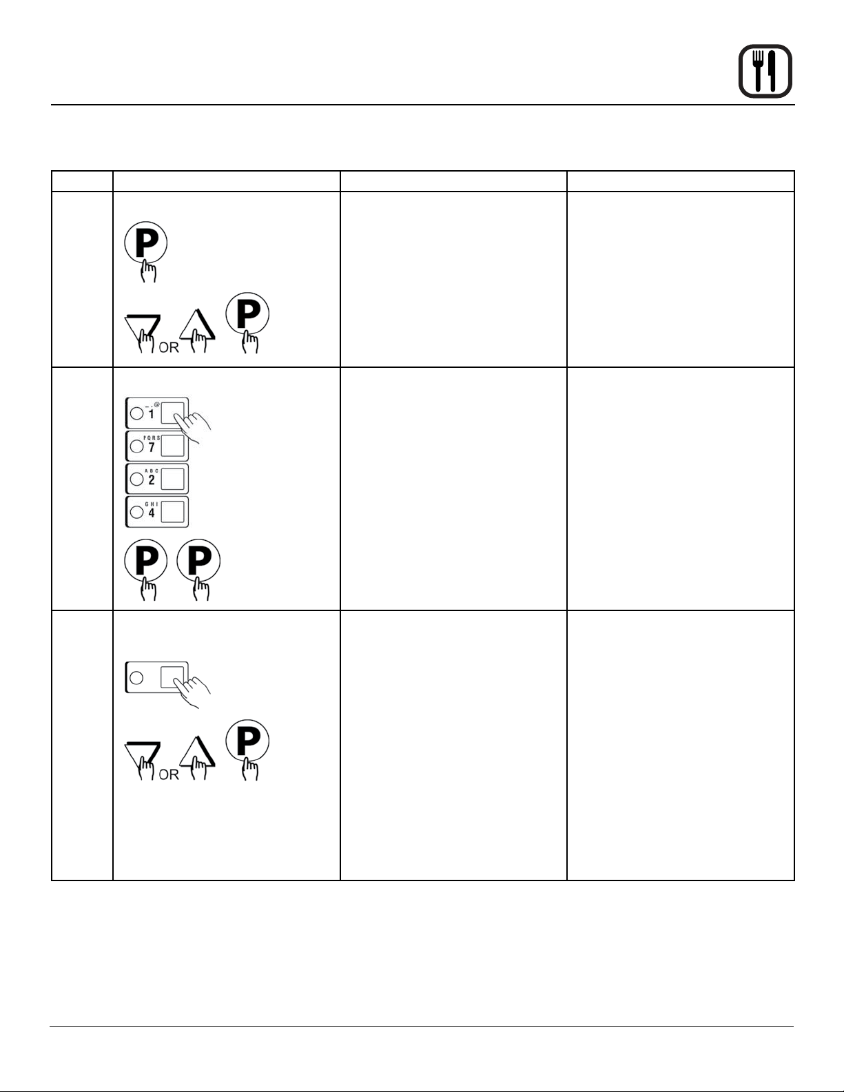
VIEW TEMPERATURE SETTING
1. Press the TEMP key ‘once’ to view Actual Temperature, or
Plug oven into electrical source
Turn the oven power switch on.
NOTE: AP and Mark V computer is unpowered if off.
NOTE: This scrolling can be bypassed by pressing ScAN.
The controller will scroll through the following:
a.) Appliance Type
b.) Software #
c.) Download #
d.) SCK Address
e.) “PREHEAT”
The oven will enter “PREHEAT” mode and begin to warm up. When the set temperature (default 325°F) is
reached, the Preheat timer will count down from 45 minutes to zero. When “LOAD” is displayed, the oven
is ready for use.
Press any illuminated product key.
The cook cycle will count down in the display.
COOL DOWN
1. To enter Cool Down, press the COOL DOWN key
while the oven door is closed. When the display reads
“COOL,” the door can then be opened.
WARNING!!
THE FAN IS STILL MOVING. DO NOT REACH
INTO THE OVEN. The fan will automatically
shut off when the actual temperature reaches
105°F.
2. To exit Cool Down, press the COOL DOWN key again.
The oven will come back up to set temperature.
2. Press the TEMP key ‘twice’ to view Set Temperature.
3. Press the TEMP key ‘three’ times to view Fan Speed
4. Press the TEMP key ‘four’ times to view Fan Direction
WARNING!!
ALWAYS TURN OFF MAIN POWER BEFORE
REMOVING BAFFLE OR PLACING HANDS
NEAR FAN.
9
Page 12
Operation
IQ VVC-208 Control
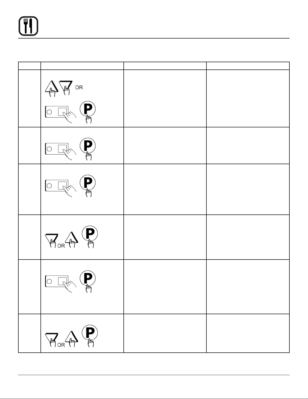
SETBACK
1. Used to manually reduce the set temperature tem-
porarily during times of infrequent cooking. Press the
SETBACK key once to reduce the set temperature to
the pre-programmed setback temperature.
2. Press the SETBACK key again to exit Setback and
warm back up to the operating temperature.
PROGRAMMING
1. Programming Mode for the Vision Controller is entered by pressing the “P” key for three (3) seconds.
The following programming mode is available on the
VVC-208 as follows:
Access Level Passcode
Employees 1724
Managers 6647
Program Area Employee Manager
System n/a X
CHANGING THE MENU STRIP
1
Turn off the oven power.
2
With a Phillips screwdriver, remove the two
screws that secure the bezel of the VVC-208 in
place. Remove the bezel.
3
Remove the existing menu strip(s) by lifting the
tab and pulling the menu strip out from the bottom of the controller.
4
Using the tab as a guide, slide the new menu
strip in.
5
Replace the bezel and screws that secure it to
the controller.
6
Turn on the oven power.
Recipe X n/a
Product Name
Library
Alarm Library X X
SCK Address X X
NOTE: Pressing the “P” key saves the previous param-
eter.
NOTE: If no key is pressed within 2 minutes while in Pro-
gramming mode, the controller will automatically
return to idle mode.
NOTE: All scrolling will loop back through allowed values.
X X
10
Page 13
RECIPE PROGRAMMING (1724)
KEY PRESS DISPLAY ACTION
Operation
IQ VVC-208 Control
1
2
Enter Program mode
Enter Pass Code
ENTER CODE
**** RECIPE
• To enter programming mode,
press and hold the “P” key for
3 seconds.
• Scroll down to “Programming”
• Press the “P” key to lock in
entry
• The display will prompt user
to enter a pass code
• Enter pass code 1 7 2 4
• Press the “P” key to lock in
your entry
• Display will show “Recipe.”
Press the “P” key
3
Choose a Product Key (Recipe)
SELECT PRODUCT TO
PROGRAM
Choices are: ALL, NAME, TIME,
TEMPERATURE, TIMING,
SENSITIVITY, FAN SPEED FAN
CYCLE, FAN PULSE ON, FAN
PULSE OFF, ALARM TIME,
ALARM NAME, ALARM DONE,
ALARM TONE, HOLD TIME,
HOLD TEMP, HOLD DONE,
HOLD FAN SPEED,
PRODUCTS HEADS, EXIT
• Press the product key to be
programmed. That key’s LED
will remain lit
• Scroll to the feature you want
changed and press the “P”
key
NOTE: Selecting “ALL” al-
lows you to review
and/or change all parameters for that key.
• To jump to a specic feature,
select one from the list and
follow the appropriate instructions to make the changes
11
Page 14
Operation
IQ VVC-208 Control
RECIPE PROGRAMMING (1724)
KEY PRESS DISPLAY ACTION
4
5
6
7
Choose a Product Name
Set Stage 1 Cook Time
Set Stage 1 Temperature
Set Stage 1 Timing
PRODUCT NAME • Press the UP or DOWN arrow
keys to scroll through product names, OR start spelling
the desired product name by
using the top row of lettered
product keys
• Press the “P” key to lock in
selection
STAGE 1 TIME
MM:SS
STAGE 1 TEMP
XXX F
STAGE 1 TIMING
(STRAIGHT, FLEX or
SENSITIVITY)
• Type in the time for Stage 1
• Range is from 00:00 to 99:59
• Press the “P” key to advance
to next stage or parameter
• Type in the Setpoint temperature for this stage. Range
is from 140 to 500F, or the
equivalent of Degrees C
• Press the “P” key to advance
to the next stage or parameter
• Press the LEFT or RIGHT
arrow keys to select the type
of timing to be used for this
stage
• Press the “P” key to advance
to next stage or parameter
7A
8
Set Sensitivity
Set Stage 1 Fan Speed
STAGE 1 SENS
(0 9)
STAGE 1 FAN SPEED
(HIGH, LOW)
12
• THIS ONLY APPEARS IF
SENSITIVITY IS SELECTED
ABOVE
• Type in Sensitivity setting of
0-9
• Press the “P” key to advance
to next stage or parameter
• Press the LEFT or RIGHT
arrow keys to select the fan
speed
• Press the “P” key to advance
to next stage or parameter
Page 15

RECIPE PROGRAMMING (1724)
KEY PRESS DISPLAY ACTION
Operation
IQ VVC-208 Control
9
9A
9B
10
Set Stage 1 Fan Cycle
Set Stage 1 Fan ON
Set Stage 1 Fan OFF
STAGE 1 FAN CYCLE
(FULL, HEAT, PULSE)
STAGE 1 FAN ON NOTE: THIS SECTION ONLY
STAGE 1 FAN OFF NOTE: THIS SECTION ONLY
If applicable, repeat steps 5-9 for additional stages.
A total of 9 stages can be programmed.
• Press the LEFT or RIGHT
• Press the “P” key to advance
• Type in desired fan ON time
• Press the “P” key to advance
• Type in desired fan OFF time
• Press the “P” key to advance
arrow keys to select the fan
cycle
to next stage or parameter
APPEARS IF “PULSE”
IS SELECTED FOR FAN
CYCLE.
to next stage or parameter
APPEARS IF “PULSE”
IS SELECTED FOR FAN
CYCLE.
to next stage or parameter
11
12
Set Alarm 1 Time (Selectable)
Set Alarm 1 Name (Selectable)
ALARM 1 TIME
MM:SS
ALARM 1 NAM
“ACTION”
13
• Type in Alarm Time for
activating the Action Alarm.
Skip Steps 11-14 if the Alarm
Time for this stage is zero
• Press the “P” key to advance
to the next stage or parameter
• Press the UP or DOWN arrow keys to scroll through
the Alarm Names, OR start
spelling the desired action
alarm name by pressing the
appropriate product keys
• Press “P” key to lock in the
selection
Page 16

Operation
IQ VVC-208 Control
RECIPE PROGRAMMING (1724)
KEY PRESS DISPLAY ACTION
13
14
15
16
17
Set Alarm #1
Done Mode (selectable)
Setting Alarm 1 Tone
Select Hold Time
Set Hold Temp
ALARM 1 DONE
(AUTOMATIC, MANUAL)
ALARM 1 TONE SHORT,
MEDIUM, LONG, DOUBLE,
LONG/ SHORT, NONE
If applicable, repeat Steps 10-13 for additional Action Alarms.
A total of three (3) Action Alarms can be programmed.
HOLD TIME
00:00
HOLD TEMP
XXXF
• Press the LEFT or RIGHT
arrow keys to select how the
Action Alarm is to be canceled
• Press the “P” key to advance
to next stage or parameter
• Press the LEFT or RIGHT arrow keys to select Alarm Tone
• Press the “P” key to advance
to next stage or parameter
• Type in the length of hold
time required. The value is in
the range of 00:00 to 99:59
• Press the “P” key to advance
to the next step or parameter
• Type in desired Hold temperature
• Press the “P” key to advance
to the next step or parameter
18
19
Set Hold Done
Set Hold Fan Speed
HOLD DONE
(AUTOMATIC, MANUAL)
HOLD FAN SPEED
(HIGH, LOW)
14
• Press the LEFT or RIGHT
arrow keys to select how the
hold alarm is to be cancelled
• Press the “P” key to advance
to the next step or parameter
• Press the LEFT or RIGHT
arrow keys to select the hold
fan speed
• Press the “P” key to advance
to the next step or parameter
Page 17

RECIPE PROGRAMMING (1724)
KEY PRESS DISPLAY ACTION
Operation
IQ VVC-208 Control
20
21
Set Product Heads
Select Another Product Key SELECT PRODUCT TO
PRODUCT HEADS
XX
PROGRAM
• Type in the proper count
value
• The range is 0-99 pieces
• Press the “P” key to advance
• Repeat from step #3 in this
section, or press the “P” key
and scroll to Exit
• Press the “P” key to exit programming
15
Page 18

Operation
IQ VVC-208 Control
SYSTEM PROGRAMMING (6647)
KEY PRESS DISPLAY ACTION
1
2
Enter Program mode
Enter pass code
ENTER CODE
****
• To enter programming mode,
press and hold the “P” key for
3 seconds
• Scroll down to Programming
• Press the “P” key to lock in
your entry
• The display will prompt user
to enter a pass code
• Enter pass code 6 6 4 7
• Press the “P” key when “Sys-
tem” is displayed
• Press the “P” key again to enter System Programming
3
4
Conrm or Select Appliance Type
Select Language
APPLIANCE TYPE
(ELECTRIC HALF,
ELECTRIC FULL)
HALF = AP
FULL = MARK V
SELECT LANGUAGE
(English, Other)
• Press the LEFT or RIGHT
arrow keys to select from a
pre-programmed list of appliances
NOTE: Changing appliance
type clears all current
recipe programs.
• Press the “P” key to lock in
your entry
• Press the LEFT or RIGHT arrow key to select language
• Press the “P” key to lock in
your entry
NOTE: ‘Other’ is download-
able.
16
Page 19

SYSTEM PROGRAMMING (6647)
KEY PRESS DISPLAY ACTION
Operation
IQ VVC-208 Control
5
6
7
Set Tone Level
Set Temperature Mode
Program Setback Time
TONE LEVEL
(None, 1, 2, 3, 4)
TEMPERATURE
F = FAHRENHEIT or
C = CELSIUS
SETBACK TIME
HH:MM
• Press the LEFT or RIGHT
arrow keys to select a tone
level. At each level the controller will continuously sound
the selected tone
• Press the “P” key to lock in
your entry
• Press the LEFT or RIGHT arrow keys to select the method
that all temperatures will be
displayed in
• Press the “P” key to lock in
your entry
• Press the numbered product
keys to select the time in
HH:MM format for activating
Setback mode
NOTE: 0:00 is default to dis-
able Setback.
• Press the “P” key to lock in
your entry
8
9
10
Program Setback Temperature
Set Hold Time
Set Hold Temperature
SETBACK TEMP
XXX
HOLD TIME
HH:MM
HOLD TEMP
XXX
• Press the numbered product
keys to select the Setback
temperature in the range of
140-300°F
• Press the “P” key to lock in
your entry
• Type in the length of hold
time required. The value is in
the range of 00:00 to 99:59
• Press the “P” key to advance
to the next stage or parameter
• Type in the desired Hold temperature. Hold Temperature
Range is 140-210°F
• Press the “P” key to advance
to the next stage or parameter
17
Page 20

Operation
IQ VVC-208 Control
SYSTEM PROGRAMMING (6647)
KEY PRESS DISPLAY ACTION
11
Set Hold Done
HOLD DONE
(AUTOMATIC, MANUAL)
• Press the LEFT or RIGHT arrow keys to select Hold Done
• Press the “P” key to advance
to the next stage or parameter
12
13
14
15
Set Hold Fan Speed
Set Preheat Time
Exit Program Mode
HOLD FAN SPEED
(HIGH, LOW)
PREHEAT TIME
MM:SS
EXIT • Press the UP or DOWN arrow
• Press the LEFT or RIGHT
arrow keys to select Hold Fan
Speed
• Press the “P” key to advance
to the next stage or parameter
• Type in the desired Preheat
Time
• Press the “P” key to advance
to the next stage or parameter
keys to scroll to “Exit”
• Press the “P” key to return to
idle mode
18
Page 21

PRODUCT OR ALARM NAME LIBRARIES (6647)
KEY PRESS DISPLAY ACTION
Operation
IQ VVC-208 Control
1
2
3
Enter Program mode
Enter Pass Code
SYSTEM PROGRAMMING
****
PROD NAME LIB or
ALARM LIB
• To enter programming mode,
press and hold the “P” key for
3 seconds
• Scroll Down to Programming
• Press the “P” key to lock in
your entry
• Enter pass code 6 6 4 7
• Press the “P” key to lock in
your entry
• Scroll to “Prod Name Lib” or
“Alarm Lib”
• Press the “P” key to advance
4
4A
4B
From this point, you can either MODIFY an Existing Name, or ADD a New Name.
MODIFY or ADD an Existing Product or Alarm Name
Prod Name Lib xxxxxxxx
OR
Alarm Name Lib xxxx
19
• Start spelling the name (predictive method) using keys
1-10, OR
• Use the UP and DOWN arrow keys to scroll through the
library (traditional method)
• Once name is located, press
the SCAN key to toggle from
predictive text input to traditional text input
Page 22

Operation
IQ VVC-208 Control
PRODUCT OR ALARM NAME LIBRARY (6647)
KEY PRESS DISPLAY ACTION
4C
4D
SAVE LIBRARY
MODIFY, ADD, CANCEL
• Use the LEFT and RIGHT arrow keys to move the cursor
• Press “HOLD” to toggle between Upper and Lower case
• “TEMP/TOGGLE CLEAR”
can be used to clear the
existing product name
• Press the “P” key to complete
• Press the LEFT or RIGHT
arrow keys to select “Modify”
or “Add”
• Press the “P” key
4E
NOTE: Selecting “cancel”
allows you to exit
without making any
changes.
Exit Program Mode EXIT • Press the UP or DOWN arrow
keys to scroll to “Exit”
20
Page 23

SCK ADDRESS (6647)
Operation
IQ VVC-208 Control
KEY PRESS DISPLAY ACTION
1
2
Enter Program Mode
Enter Pass Code
ENTER CODE
****
• To enter programming mode,
press and hold the “P” key for
3 seconds
• Scroll to Programming
• Press the “P” key
• The display will prompt user
to enter a pass code
• Enter pass code 6 6 4 7
• Press the “P” key to lock in
your entry
• Scroll to SCK Address
• Press “P” to advance
3
4
5
Set SCK Address
Set SCK Node NETWORK NODES
Exit SCK Programming
SCK ADDRESS
XX
XX XX XX XX XX
EXIT • Scroll to Exit
• Press the LEFT or RIGHT ar-
• Press the “P” key to lock in
• The display will scroll in
• Press the “P” key to advance
• Press the “P” key to return to
row keys to scroll through the
SCK address to be used for
this controller. The range is
from 1 to 31, or “Auto Assign”
your selection
marquee-style all SCK Nodes
currently in the system.
Scrolling will constantly be
updated
idle
21
Page 24

Operation
Blodgett IQ™ Phase IV Control
COMPONENT DESCRIPTION
NOTE: Phase IV controls have two squares at the bottom
of the control.
1. OVEN POWER SWITCH controls power to the oven.
2. FUSES Provide oven circuit protection.
3. TOP DISPLAY displays temperature and other controller related information.
4. PROG LED when lit indicates the controller is in the
programming mode.
5. FAN HI LED when lit indicates the fans are running at
high speed.
6. BOTTOM DISPLAY displays cook time and other
controller related information.
7. HEAT LED when lit indicates the control is calling for
heat.
8. FAN LO LED when lit indicates the fans are running
at low speed.
Figure 7
9. COOL DOWN KEY press to enter the cool down
mode.
10. PROG KEY press to enter the programming mode.
11. TOGGLE/CLEAR KEY press during programming to
toggle options.
12. ACT TEMP KEY press to display the actual oven temperature.
13. SET TEMP KEY press to display the programmed
cook temperature for the current stage of the product
key.
14. ENTER KEY press to enter new values into product
key programming. Also used to view recovery time.
15. SCAN KEY completes the programming for the current parameter and advances the controller to the
next parameter. Press to view time remaining on multiple cook cycles.
16. PRODUCT LEDS when lit indicate which product
keys are currently in use or programmed for the current oven temperature and fan speed.
17. PRODUCT KEYS assigns a key to a programmed
recipe and begins a programmed cooking process.
22
Page 25

Operation
Blodgett IQ™ Phase IV Control
OVEN OPERATION
Oven Startup:
1. Toggle the POWER SWITCH (1) to ON. The oven
preheats to the lowest programmed rst stage temperature. The LEDS (16) for all products with the
same rst stage temperature light.
While the unit preheats the TOP DISPLAY (3) gives
the actual temperature. The BOTTOM DISPLAY (6)
reads Lo if the oven is more than 10° below setpoint.
When the oven reaches ±10° of the preheat temperature an alarm sounds and the bottom display reads
LoAd.
Single Product Cooking Procedure:
NOTE: If the led next to the desired product key is lit skip
step 1.
1. Press the desired PRODUCT KEY (17). The oven
preheats to the rst stage temperature for the selected product. When the oven reaches ±10° of the
preheat temperature an alarm sounds and the bottom
display reads LoAd.
2. Load the product into the oven. Press the selected
PRODUCT KEY (17) to start the cook cycle. The LED
(16) next to the selected product key ashes. The top
display reads ----. The bottom display counts down
the cook time in minutes:seconds.
NOTE: If the selected product has a cook time of
greater than 59:59 the top display reads
Hr-- for the total number of hours. The bottom display counts down the cook time in
minutes:seconds.
NOTE: If the selected product is a single stage reci-
pe the LEDS for all single stage products with
the same cook temperature and fan speed
will light. If the selected product is a multiple
stage recipe no other product LEDS will light.
NOTE: Press and hold the selected product key for
three seconds to cancel the cook cycle.
3. When the cook time expires an alarm sounds and the
top display reads donE.
4. Press the selected product key to silence the alarm.
Remove the product.
Multiple Batch Cooking Procedure:
This procedure is for single stage recipes with the same
cook temperature and fan speed only.
NOTE: If the led next to the rst desired product key is lit
skip step 1.
1. Press the rst desired PRODUCT KEY (17). The
LEDS for all recipes with the same cook temperature
and fan speed will light.
The oven preheats to the cook temperature for the
selected product. When the oven reaches ±10° of the
preheat temperature an alarm sounds and the bottom
display reads LoAd.
2. Load the rst product into the oven. Press the selected PRODUCT KEY (17) to start the cook cycle. The
LED (16) next to the selected product key ashes.
The top display reads ----. The bottom display counts
down the cook time in minutes:seconds.
3. Load the second product. Press the appropriate
PRODUCT KEY (17).
NOTE: Only products with lighted LEDS may be se-
lected.
4. The led for the product with the least time remaining
ashes faster than the led for the other product. The
TOP DISPLAY (3) reads ----. The BOTTOM DISPLAY
(6) counts down the cook time for the product with the
least time remaining.
NOTE: To view the remaining cook time for the other
product press and hold the SCAN KEY (15).
The bottom display cycles through the remaining cook times for each product. Only
the led for the product with the cook time displayed will be lit.
5. When a cook time expires an alarm sounds. The top
display reads donE. The led for the nished product
lights. All other LEDS are dark.
6. Press the PRODUCT KEY (17) for the nished product to silence the alarm. Remove the product. Close
the oven door. The TOP DISPLAY (3) reads ----. The
BOTTOM DISPLAY (6) counts down the cook time for
the other product.
7. When the cook time expires an alarm sounds and the
top display reads donE.
8. Press the PRODUCT KEY (17) to silence the alarm.
Remove the product.
23
Page 26

Operation
Blodgett IQ™ Phase IV Control
Using PreAlarms:
1. The top display reads AX_ _ .
NOTE: A indicates the alarm function. X is the pre-
alarm number. _ _ is the alarm time.
The LED for the active product key ashes. All other
LEDS are off. The function keys are disabled.
2. If a manual PreAlarm is activated, press the product
key to silence the alarm.
If an automatic PreAlarm is activated the alarm
sounds for approximately 5 seconds then stops automatically. Press the product key to silence automatic
PreAlarms.
Using Head Count:
Use the following instructions to display the current head
count for an individual product key.
1. Press the SCAN KEY (15) and the desired product
key simultaneously. The top display reads HOXX.
NOTE: HO indicates the head count function. XX in-
dicates product 1 to 16.
The bottom display gives the total number of heads
cooked from 1 to 9999. The product key LED remains
lit.
2. Press the TOGGLE/CLEAR KEY (11) to reset the
counter if desired.
Oven Cool Down:
1. Close the oven door. Press the COOL DOWN KEY
(9).
NOTE: Cool down cannot be activated with the oven
door open. Once the cool down cycle has begun the doors may be opened to speed the
cooling process.
3. Press the SCAN KEY (15) to exit.
Use the following instructions to display the total head
count.
1. Press the SCAN KEY (15) and the ENTER KEY (14)
simultaneously. The top display reads HEAd. The bottom display gives the total number of heads cooked
from 1 to 9999. All product LEDS remain lit
2. Press the TOGGLE/CLEAR KEY (11) to reset the
counter if desired.
NOTE: Clearing the total head count also clears in-
dividual product head counts.
3. Press the SCAN KEY (15) to exit.
24
Page 27

Operation
Blodgett IQ™ Phase IV Control
PROGRAMMING SINGLE STAGE RECIPES
NOTE: Refer to the KFC Standards Library for actual
recipes.
Entering the Programming Mode:
1. Press the PROG KEY (10). The top display reads
codE.
2. Use the product keys to enter the programming access code: 3 1 2 4. Press the ENTER KEY (14). The
top display reads Prod.
3. Press the desired product key followed by the ENTER KEY (14).
Programming the Cook Time:
NOTE: If the product has a cook time of greater than
59:59 the top display reads Px-- for the product,
stage and hours. The bottom display counts down
the cook time in minutes:seconds.
1. The top display reads P1:_ _. The bottom display
gives the current programmed cook time for stage
1 in minutes:seconds. Press the TOGGLE/CLEAR
KEY (11). Use the product keys to enter the new cook
time. Press the ENTER KEY (14) to save the new
cook time.
2. The top display reads P2_ _. The control is asking
for the cook time for stage 2 of this recipe. Press the
TOGGLE/CLEAR KEY (11) to enter a time of 0:00:00
for P2:.
NOTE: This tells the controller that there are no more
stages for this recipe. Once a single stage
recipe has been established the control will
only allow entries for one stage on all further
parameters for this product.
3. Press the ENTER KEY (14) again. The top display
reads P1:. The bottom display shows the cook time.
Programming the Fan Speed:
1. The top display reads SPd1. The bottom display gives
the current fan speed. Press the TOGGLE/CLEAR
KEY (11). The bottom display toggles between HI and
Lo.
2. Press the SCAN KEY (15) to advance the programming mode to the fan cycle time.
Programming the Fan Cycle Time:
There are 3 options for fan cycle time: Pulse, Heat and
Full. Pulse allows the fan to turn on and off as programmed. Heat allows the fan to operate with heat only.
Full provides continuous fan operation.
1. The top display reads cYc1. The bottom display gives
the current fan cycle. Press theTOGGLE/CLEAR
KEY (11). The bottom display toggles between PULS,
HEAt and FULL.
2. If heat or full are selected press the SCAN KEY (15) to
save the new fan cycle and advance to timing mode.
If pulse is selected press the SCAN KEY (15) and
continue with Steps 3-4 to program the pulse cycle.
3. The top display reads on-1. The bottom display gives
the current pulse on time. Use the product keys to enter the desired pulse on time from 10 to 60 seconds.
Press the SCAN KEY (15).
4. The top display reads of-1. The bottom display gives
the current pulse off time. Use the product keys to enter the desired pulse off time from 10 to 60 seconds.
Press the SCAN KEY (15) to advance the programming mode to timing mode.
4. Press the SCAN KEY (15) to advance the programming mode to cook temperature.
Programming the Cook Temperature:
1. The top display reads ct-1. The bottom display gives
the current cook temperature. Use the product keys
to enter the desired cook temperature.
2. Press the SCAN KEY (15) to advance the programming mode to fan speed
25
Page 28

Operation
Blodgett IQ™ Phase IV Control
Programming the Timing Mode:
There are 3 options for timing mode: Straight, Flex and
Sensitivity.
1. The top display reads tc-1. The bottom display gives
the current timing mode. Press the TOGGLE/CLEAR
KEY (11) to toggle between St, FL and SEns.
2. If straight or ex are selected press the SCAN KEY
(15) to advance the programming mode to PreAlarms.
3. If sensitivity is selected press the SCAN KEY (15) and
continue with Steps 4-5.
NOTE: Sensitivity adjusts the cook time to compen-
sate for any difference between the setpoint
and actual temperature. The lower the sensitivity value the shorter the time adjustment.
4. The top display reads SE-1. Use the product keys to
enter the desired sensitivity from 0-9.
5. Press the SCAN KEY (15) to advance the programming mode to PreAlarms.
Programming the PreAlarms:
A PreAlarm is an alarm that sounds during the cook cycle.
PreAlarms can be used to alert the operator that the product needs to be turned or stirred, etc. Up to three PreAlarms can be programmed for each product.
1. The top display reads A1_ . (The _ indicates the product key) The bottom display gives the alarm time. Use
the product keys to enter the desired time for the rst
alarm. Press the ENTER KEY (14) to enter the PreAlarm time.
4. The top display reads A2_. Repeat steps 1-3 for the
second and third PreAlarm. When all PreAlarms have
been entered the control advances to programming
the head count.
Programming the Head Count:
1. The top display reads HEAd. The bottom display
gives the current number of heads programmed for
this product key. Use the product keys to enter the
desired number of heads from 1-99.
2. Press the SCAN KEY (15). The programming for this
recipe is now complete.
Exiting the programming mode:
1. The top display reads Prod. Press the PROG KEY
(10). The control returns to operating mode.
NOTE: PreAlarm times are measured from the end
of the total cook time. For example if the total
cook time is 30:00 and a PreAlarm of 5:00 is
entered, the alarm will sound 25 minutes into
the cook cycle. If a PreAlarm of 0:00 is entered, no additional PreAlarms may be programmed for the selected product key.
2. Press the SCAN KEY (15).
3. The top display reads AUTo. The bottom display
reads either YES or no. Press the TOGGLE/CLEAR
KEY (11) to toggle between YES and no. Press the
SCAN KEY (15) to enter the PreAlarm type.
NOTE: An auto PreAlarm sounds for approximately
5 seconds, then shuts off automatically. For
manual PreAlarms the operator must press
the product key to silence the alarm.
26
Page 29

Operation
Blodgett IQ™ Phase IV Control
PROGRAMMING MULTIPLE STAGE RECIPES
NOTE: Refer to the KFC Standards Library for actual
recipes.
Entering the Programming Mode:
1. Press the PROG KEY (10). The top display reads
codE.
2. Use the product keys to enter the programming access code: 3 1 2 4. Press the ENTER KEY (14). The
top display reads Prod.
3. Press the desired product key followed by the ENTER KEY (14).
Programming the Cook Time:
NOTE: If any stage of the product has a cook time of
greater than 59:59 the top display reads Px- - for
the product, stage and hours. The bottom display
counts down the cook time in minutes:seconds.
1. The top display reads P1:_ _. The bottom display
gives the current programmed cook time for stage
1 in minutes:seconds. Press the TOGGLE/CLEAR
KEY (11). Use the product keys to enter the new cook
time. Press the ENTER KEY (14) to save the new
cook time.
2. The top display reads P2:_ _. The control is asking
for the cook time for the second stage of this recipe.
Repeat Step 1 for each additional stage.
3. When the cook times for all stages are programmed,
press the TOGGLE/CLEAR KEY (11) to clear the bottom display.
Programming the Cook Temperature:
1. The top display reads ct-1. The bottom display gives
the current cook temperature for stage 1 of this recipe. Use the product keys to enter the desired cook
temperature.
2. Press the ENTER KEY 14 to save the new cook temperature for stage 1. The top display reads Ct-2.
NOTE: Repeat Steps 1-2 to program the cook
temperature for additional stages. When the
cook temperature for the nal stage has been
entered the top display reads ct-1.
3. Press the SCAN KEY (15) to advance the programming mode to fan speed
Programming the Fan Speed:
1. The top display reads SPd1. The bottom display gives
the current fan speed for stage 1. Press the TOGGLE/CLEAR KEY (11). The bottom display toggles
between HI and Lo.
2. Press the ENTER KEY 14 to save the new fan speed
for stage 1. The top display reads SPd2.
NOTE: Repeat Steps 1-2 to program the fan speed
for additional stages. When the fan speed for
the nal stage has been entered the top display reads SPd1.
3. Press the SCAN KEY (15) to advance the programming mode to the fan cycle time.
NOTE: This tells the controller that there are no
more stages for this recipe. Once the number
of stages has been established the control
will only allow entries for these stages on all
further parameters for this product.
4. Press the ENTER KEY (14) again. The display reads
P1:. The bottom display shows the cook time.
5. Press the SCAN KEY (15) to advance the programming mode to cook temperature.
27
Page 30

Operation
Blodgett IQ™ Phase IV Control
Programming the Fan Cycle Time:
There are 3 options for fan cycle time: Pulse, Heat and
Full. Pulse allows the fan to turn on and off as programmed. Heat allows the fan to operate with heat only.
Full provides continuous fan operation.
1. The top display reads CYC1. The bottom display
gives the current fan cycle for stage 1. Press the
TOGGLE/CLEAR KEY (11). The bottom display toggles between PULS, HEAT and FULL.
2. Press the ENTER KEY 14 to save the new fan cycle
for stage 1. The top display reads CYC2.
NOTE: Repeat Steps 1-2 to program the fan cycle for
additional stages.
3. When the fan cycle for the nal stage has been entered press the SCAN KEY (15).
If no pulse cycles are programmed the control advances to timing mode.
If pulse is used, the control returns to the rst stage
programmed for the pulse fan option. Follow Steps
4-5 to program the pulse on and off time.
4. The top display reads on-x. The bottom display gives
the current pulse on time for this stage. Use the product keys to enter the desired pulse on time from 10 to
60 seconds. Press the SCAN KEY (15).
5. The top display reads of-x. The bottom display gives
the current pulse off time. Use the product keys to enter the desired pulse off time from 10 to 60 seconds.
Press the SCAN KEY (15). The control advances to
the next stage programmed for the pulse fan option.
Programming the Timing Mode:
NOTE: It may be necessary to press the ENTER KEY 14
until the top display reads tc-1.
There are 3 options for timing mode: Straight, Flex and
Sensitivity.
1. The top display reads tc-1. The bottom display gives
the current timing mode. Press the TOGGLE/CLEAR
KEY (11) to toggle between St, FL and SEns.
2. Press the ENTER KEY 14 to save the new timing
mode for stage 1. The top display reads tc-2.
NOTE: Repeat Steps 1-2 to program the timing
mode for additional stages.
3. When the timing mode for the nal stage has been
entered press the SCAN KEY (15).
If no sensitivity cycles are selected the control advances to PreAlarms.
If sensitivity is used, the control returns to the rst
stage programmed with sensitivity. Follow Step 4 to
program the sensitivity level.
4. The top display reads SE-1. Use the product keys
to enter the desired sensitivity from 0-9. Press the
SCAN KEY (15). The control advances to the next
stage programmed for sensitivity.
NOTE: Repeat Step 4 to program sensitivity levels
for all applicable stages. When the nal sensitivity level has been entered the control advances to PreAlarms.
NOTE: Repeat Steps 4-5 to program cycle times for
all pulse fan stages. When the nal pulse off
time has been entered the control advances
to timing mode.
28
Page 31

Operation
Blodgett IQ™ Phase IV Control
Programming the PreAlarms:
A PreAlarm is an alarm that sounds during the cook cycle.
PreAlarms can be used to alert the operator that the product needs to be turned or stirred, etc. Up to three PreAlarms can be programmed for each product.
1. The top display reads A1_. (The _ indicates the product key) The bottom display gives the alarm time. Use
the product keys to enter the desired time for the rst
alarm. Press the ENTER KEY (14) to enter the PreAlarm time.
NOTE: PreAlarm times are measured from the end
of the total cook time. For example if the total
cook time is 30:00 and a PreAlarm of 5:00 is
entered, the alarm will sound 25 minutes into
the cook cycle. If a PreAlarm of 0:00 is entered, no additional PreAlarms may be programmed for the selected product key.
2. Press the SCAN KEY (15).
3. The top display reads AUTO. The bottom display
reads either YES or no. Press the TOGGLE/CLEAR
KEY (11) to toggle between YES and no. Press the
SCAN KEY (15) to enter the PreAlarm type.
Programming the Head Count:
1. The top display reads HEAd. The bottom display
gives the current number of heads programmed for
this product key. Use the product keys to enter the
desired number of heads from 1-99.
2. Press the SCAN KEY (15). The programming for this
recipe is now complete.
Exiting the programming mode:
1. The top display reads Prod. Press the PROG KEY
(10). The control returns to operating mode.
NOTE: An auto PreAlarm sounds for approximately
5 seconds, then shuts off automatically. For
manual PreAlarms the operator must press
the product key to silence the alarm.
4. The top display reads A2_. Repeat steps 1-3 for the
second and third PreAlarm. When all PreAlarms have
been entered the control advances to programming
the head count.
29
Page 32

Operation
Blodgett IQ™ Phase IV Control
2ND LEVEL PROGRAMMING
Entering the programming mode
1. Press the PROG KEY (10). The top display reads
codE.
2. Use the product keys to enter the programming access code: 4 5 1 2. Press the ENTER KEY (14). The
top display reads SYS.
Programming hold
Hold allows product to be kept warm in the oven at a
programmed time and temperature. There are two hold
modes available, auto and manual. If auto hold is enabled
the control will automatically place the oven into the hold
mode at the end of each cooking cycle. If manual hold is
enabled the unit can be placed into the hold mode at any
time.
1. Press the SCAN KEY (15). The top display reads
Hold. Press the TOGGLE/CLEAR KEY (11) to toggle
between YES and no. Press the SCAN KEY (15).
If no is chosen:
a. The controller advances to programming the set-
back mode.
If yes is chosen:
a. The top display reads AUTO. Press the TOG-
GLE/CLEAR KEY (11) to toggle between YES
and no. Press the SCAN KEY (15) to enter the
desired hold mode.
Programming the setback mode
The setback mode operates as a power saving feature.
After a period of non-use (the setback time) the oven
temperature automatically decreases to the setback temperature. The oven will maintain this temperature until a
product key is pressed.
1. The top display reads SEtb. The bottom display gives
the setback mode. To change the setback press the
TOGGLE/CLEAR KEY (11). The bottom display toggles between YES and no. Press the SCAN KEY (15).
If no is chosen:
a. The controller advances to programming the
temperature mode.
If yes is chosen:
a. The bottom display gives the current setback
time. Press the TOGGLE/CLEAR KEY (11). Use
the product keys to the enter the desired setback
time. Press the SCAN KEY (15) to enter the new
setback time.
NOTE: The minimum setback time is 20:00. The
maximum setback time is 59:59.
b. The bottom display gives the current setback
temperature. Press the TOGGLE/ CLEAR KEY
(11). Use the product keys to the enter a setback
temperature from 140°F-300°F. Press the SCAN
KEY (15) to enter the new setback and continue
with programming the temperature mode.
b. The top display reads HOLD. The bottom display
gives the current hold time. Press the TOGGLE/
CLEAR KEY (11). Use the product keys to enter
a hold time from 0 to 9 hours. Press the SCAN
KEY (15) to enter the new hold time.
c. The top display reads HOLD. The bottom dis-
play gives the current hold temperature. Press
the TOGGLE/CLEAR KEY (11). Use the product
keys to enter a hold temperature from 140°F210°F. Press the SCAN KEY (15) to enter the
new hold temperature.
d. The top display reads FAn. The bottom display
gives the current fan mode. To change the fan
mode press the TOGGLE/ CLEAR KEY (11). The
bottom display toggles between Hi and Lo. Press
the SCAN KEY (15) to enter the new fan mode
and continue with programming the setback
mode.
Programming the temperature mode (°F or °C)
1. The top display reads dEg. The bottom display gives
the units. To change the units press the TOGGLE/
CLEAR KEY (11). The bottom display toggles between F and C.
2. Press the SCAN KEY (15) to enter the new temperature units and continue programming the oven size.
30
Page 33

Operation
Blodgett IQ™ Phase IV Control
Programming the oven size
1. The top display reads APPL. The bottom display
reads either FULL or HALF. Press the TOGGLE/
CLEAR KEY (11) until the bottom display reads FULL
for the Mark V.
2. Press the SCAN KEY (15) to enter the oven size and
continue with exiting the programming mode.
Exiting the programming mode
1. The top display reads SYS. Press the PROG KEY
(10). The control returns to the operating standby
mode.
Parameter KFC Default
Hold mode NO
Setback NO
Temperature Units °F
Appliance Size FULL
PROGRAMMING THE OFFSET
Entering the offset programming mode
1. Press the PROG KEY (10). The top display reads
codE.
2. Use the product keys to enter the offset programming
access code: 4 5 2 3. Press the ENTER KEY (14).
The top display reads oFF. The bottom display reads
SEt.
Programming the temperature offset
1. Press the SCAN KEY (15). The top display reads
oFST. The bottom display reads either xxF or -xxF.
2. Press the TOGGLE/CLEAR KEY (11) to toggle between positive and negative. Use the product keys to
the enter the desired temperature offset.
3. Press the SCAN KEY (15) to enter the new temperature offset.
Exiting the offset programming mode
1. Press the PROG KEY (10). The control returns to the
operating standby mode.
ERROR CODES AND ALARMS
NOTE: The error codes will appear in the top display.
All error codes are accompanied by an audible
alarm.
Hi Oven temperature is more than 40°F
above the highest setpoint.
Prob Probe failure.
HEAT ERR From a cool start (below 130°F), the oven
takes more than 6 minutes to climb from
150-300°F. Press the TOGGLE/CLEAR
KEY (11) to clear the prompt. This code
indicates a problem with the system. Contact a service technician.
FAN ERR Indicates a fan failure during a call for
heat. Press the TOGGLE/CLEAR KEY
(11) to clear the alarm. The FAN ERR display remains active. Press the TOGGLE/
CLEAR KEY (11) again to clear the message and return the system to normal operation. If condition persists turn off the
oven and contact a service technician.
FANC ERR Indicates a contact failure has occurred in
the fan control circuit. Press the TOGGLE/
CLEAR KEY (11) to clear the alarm. The
FANC ERR display remains active. Press
the TOGGLE/CLEAR KEY (11) again to
clear the message and return the system
to normal operation. If condition persists
turn off the oven and contact a service
technician.
DOOR OPEN The controller senses the door is open.
Close the door. If the door is closed contact a service technician.
REPLACING THE RECIPE CARD
1. Remove the two screws from the top and bottom of
the control panel cover. Remove the cover.
2. Pull back the control decal.
3. Remove the old recipe card.
4. Insert the new recipe card.
5. Replace the control decal.
6. Replace the control cover.
7. Reinstall the screws.
31
Page 34

Maintenance
Cleaning and Preventative Maintenance
CLEANING THE OVEN
Refer to KFC Equipment Standards Library Volume 2
Mark V for proper cleaning procedures.
PREVENTATIVE MAINTENANCE
The best preventative maintenance measures are, the
proper installation of the equipment and a program for
routinely cleaning the ovens. This oven requires no lubri-
cation, however, the venting system should be checked
annually for possible deterioration resulting from moisture
and corrosive ue products. If maintenance or repairs are
required, they should only be performed by qualied ser-
vice personnel.
WARNING!!
Always disconnect the appliance from the
power supply before servicing or cleaning.
32
Page 35

END-USER LICENSE AGREEMENT FOR SCK® COMMUNICATION LINK SOFTWARE
IMPORTANT READ CAREFULLY: This is a legal agreement between the end user (“YOU”), and Food Automation Service Techniques, Inc. (“FAST”), the
supplier of the SCK® Communication Link Software (the “SCK® Link Software”) which is embedded within the controller of this appliance purchased from
the BLODGETT OVEN COMPANY (“COMPANY”). The SCK® Link Software includes computer software, the associated media, operational instructions,
and any printed materials. The SCK® Link Software is used to establish communication to and from a terminal, computer, server or another controller.
By using the SCK® Link Software you agree to be bound by the terms of this End-User License Agreement (“EULA”). If you do not agree to the terms of
this EULA, promptly contact the COMPANY or FAST, and a controller that does not contain the SCK® Link Software will be provided as a replacement.
Software Product License
The SCK® Link Software is copyrighted and is protected by United States copyright laws and international treaty provisions. The SCK® Link Software is
licensed, not sold. Title, ownership rights, and intellectual property rights in the SCK® Link Software remains with FAST. You may not remove any copyright
notice of the SCK® Link Software as well as the identication mark “SCK® Communication Link” located on the front panel and communication port of the
controller.
1. License: FAST grants to you a non-transferable, nonexclusive license to:
• use the SCK® Link Software embedded within the controller only if such controller is temporarily connected to a single terminal or computer
for the exclusive purpose of conguring the operating parameters and testing of this appliance. The SCK® Link Software may only be used
with the controller.
You may not, unless under a separately purchased SCK® Network License from FAST:
• use the SCK® Link Software for peer-to-peer networking or networking of multiple FAST controllers;
• use the SCK® Link Software for the purpose of permanently connecting the FAST controller to a terminal, a computer, server or another
controller.
This requirement stands whether you purchased a server from FAST, third party application software or develop an application yourself.
2. Copyright: You agree that the SCK® Link Software is the property of FAST and is proprietary to them. You agree to use your best efforts to prevent
and protect, the contents of the SCK® Link Software, or any part of, from unauthorized use or disclosure.
3. License Fee: The SCK® Link Software license is granted in consideration for the license fee which has been paid by the COMPANY. The license fee
may have been charged separately when you purchased your controller or included in the total purchase price of the controller.
4. Description of Other Rights and Limitations: You may not:
• modify, network, rent, loan, distribute, sublicense or create derivative works based upon the SCK® Link Software in whole or in part or electronically transmit the SCK® Link Software over a network.
• disassemble, reverse compile, translate or decipher the software or protocols of the SCK® Link Software, in whole or in part, for any purpose.
No license under any existing or future patents to which FAST has rights, interest or title thereto is granted by FAST to you except that which is necessary
for the limited use of the SCK® Link Software in the form provided to you and as authorized herein.
The SCK® Link Software contains copyrighted material, trade secrets and other proprietary material and in order to protect them you may not decompile,
reverse engineer, disassemble or otherwise reduce the SCK® Link Software to a human-perceivable form.
All your rights under the EULA are transferred with the controller, and the recipient agrees to abide by the terms of the EULA. Once you have transferred
the controller all your rights under this EULA are terminated.
5. Termination: Without prejudice to any other rights, FAST may terminate this EULA without refund if you fail to comply with the terms and conditions
of this EULA.
6. Limited Warranty: FAST WARRANTS THAT THE SCK® LINK SOFTWARE WILL, UNDER NORMAL AND ANTICIPATED USE, AND WHEN USED
IN THE SPECIFIED OPERATING CONDITIONS, BE FREE FROM MATERIAL OPERATING DEFECTS FOR TWO (2) YEARS FROM THE DATE
OF PURCHASE. IF ANY CLAIM IS MADE THAT THE SCK® LINK SOFTWARE INFRINGES THIRD PARTY INTELLECTUAL PROPERTY, FAST’S
OBLIGATIONS SHALL BE EXCLUSIVELY SET FORTH IN 2-312(3) AND 2-607 OF THE CONNECTICUT UCC. FAST WILL BE OBLIGATED ON
ANY CLAIM ONLY IF (1) YOU HAVE PROVIDED US WITH PROMPT NOTICE OF ANY SUCH CLAIM; AND (2) ANY SUCH CLAIM IS NOT BASED
UPON YOUR FAILURE TO INSTALL AND OPERATE THE GOODS IN ACCORDANCE WITH OUR SPECIFICATIONS AND DIRECTIONS; AND (3)
ANY SUCH CLAIM IS NOT ATTRIBUTABLE TO EQUIPMENT OR OTHER DEVICES SUPPLIED BY ANYONE BUT FAST; AND (4) YOU ALLOW US
TO CONTROL THE DEFENSE AGAINST OR OTHER OPPOSITION TO SUCH CLAIM, INCLUDING THE SETTLEMENT OF SUCH CLAIM AND
ANY RELATED PROCEEDINGS.
7. No Other Warranties: EXCEPT AS SET FORTH ABOVE, FAST DISCLAIMS ALL OTHER WARRANTIES, EXPRESS OR IMPLIED, INCLUDING
WITHOUT LIMITATION, ANY WARRANTIES AS TO THE SUITABILITY, MERCHANTABILITY OR FITNESS WITH REGARD TO THE SCK® LINK
SOFTWARE.
8. No Liability for Consequential Damages: IN NO EVENT SHALL FAST BE LIABLE FOR ANY LOST OR ANTICIPATED PROFITS, OR ANY INCIDENTAL, EXEMPLARY, SPECIAL, OR CONSEQUENTIAL DAMAGES ARISING OUT OF THE USE OF OR INABILITY TO USE THE SCK® LINK
SOFTWARE, REGARDLESS OF WHETHER FAST WAS ADVISED OF THE POSSIBILITY OF SUCH DAMAGES. SOME JURISDICTIONS DO NOT
ALLOW THE LIMITATION OR EXCLUSION OF LIABILITY FOR INCIDENTAL OR CONSEQUENTIAL DAMAGES SO THE ABOVE LIMITATION OR
EXCLUSION MAY NOT APPLY TO YOU. IN NO EVENT SHALL FAST’S TOTAL LIABILITY TO YOU FOR ALL DAMAGES, LOSSES AND CAUSES
OF ACTION, WHETHER IN CONTRACT, TORT, NEGLIGENCE OR OTHERWISE, EXCEED THE AMOUNT PAID BY YOU FOR THE SCK® LINK
SOFTWARE.
9. U.S. Government Restricted Rights: The SCK® Link Software is provided with “Restricted Rights.” Use, duplication or disclosure by the govern-
ment is subject to restrictions as set forth in FAR52.227-19 and DFAR252.227-7013 et seq. or its successor. Use of the SCK® Link Software by the
Government constitutes acknowledgment of FAST’s proprietary rights in them. Manufacturer is Food Automation Service Techniques, Inc. Stratford
Connecticut.
THIS SOFTWARE LICENSE AGREEMENT AND WARRANTY ARE GOVERNED BY THE LAWS OF THE STATE OF CONNECTICUT, U.S.A.
APPENDIX 33
Page 36

DOUBLE STACKING
WARNING!!
Due to the height of the top racks of the upper
unit, KFC has determined double stacked ovens
to be unsafe. If a double stacked unit is desired
use the following directions for leg attachment
and stacking.
LEG AND CASTER ATTACHMENT
1. With the oven lying on it’s back, align the threaded stud
in each leg with the nut located inside each bottom front
corner of the oven frame. Turn the legs clockwise and
tighten to the nearest full turn.
NOTE: Short legs may be replaced by caster bracket
assemblies.
2. Align the two leg plate holes in each leg with those in
the oven bottom. Secure using two 1/2” bolts.
NOTE: For bolts on front and back edge of oven, hand
tighten only. They will need to be removed for
shelf installation.
3. Tip the oven up on the newly installed legs.
4. Level the oven by screwing the adjustable leg feet in or
out as necessary.
NOTE: If casters are used in conjunction with a power sup-
ply cord for movable appliances, a xed restraint
should be provided. This restraint should secure the
oven to a non-movable surface to eliminate stress
on the connector. If the oven is moved from its regular location, the restraint must be reconnected when
the oven is returned.
STACKING INSTRUCTIONS
1. Secure short legs to the bottom section as described.
2. Place the upper section in position on top of the lower
oven.
3. Place clips over the back edge of the oven frames. Secure the clips with the 3/8” bolts and nuts provided.
4. Attach the two-piece ue connector.
Restraint Cable
APPENDIX 34
Page 37

SINGLE STAGE PROGRAMMING & RECIPES
PROGRAMMING
Press the
buttons
below
1
2
3
4
5
6
7
8
9
10
11
PROG CODE —
3, 1, 2, 4
ENTER
Press button
you want to
program “3”
ENTER P1: Current cook
20:00
ENTER
SCAN Ct-1 Current cook
325
ENTER
SCAN SPD-1 Current fan
HI ENTER SPD-1 HI
SCAN CYC-1 Current cycle
TOGGLE/
CLEAR
Top display
reads
PROD —
PROD 3
P1: 20:00
Ct-1 325F
CYC-1 FULL
display reads
Bottom
time
temp
speed
time
RECIPES
Stage Temp Time
Biscuits Keys 1 & 2
1 325°F 16:00 HI FULL FL
Pot Pie Keys 3 & 4
1 325°F 22:00 HI FULL FL
Mac & Cheese Key #5
1 325°F 60:00
frozen
Mac & Cheese Key #6
1 325°F 37:00
thaw
RECIPES (Rev A 11/4/1996)
Stage Temp Time
Biscuits Keys 1 & 2
1 325°F 16:00 HI FULL FL
Mac & Cheese (Thawed) Key #5
1 325°F 37:00
thaw
Fan
HI FULL FL
HI FULL FL
Fan
HI FULL FL
Fan
Cycle Timing
Fan
Cycle Timing
12
13
14
APPENDIX 35
ENTER SHLF Current shelf
ID
TOGGLE/
CLEAR
SCAN PROD —
SHLF NO
Page 38

MULTI STAGE PROGRAMMING & RECIPES
PROGRAMMING
1
2
3
4
5
6
7
8
9
10
Press the
buttons
below
PROG CODE —
3, 1, 2, 4
ENTER
Press button
you want to
program “10”
ENTER P1: Current
1:00
ENTER
9:00
ENTER
25:00
ENTER
4:00
ENTER
TOGGLE/
CLEAR
SCAN Ct-1 Current
Top display
reads
PROD —
PROD 10
P2: Current
P3: Current
P4: Current
P5: Current
P5: 0
display reads
Bottom
cook time
cook time
cook time
cook time
cook time
cook temp
19
20
21
22
23
24
25
26
27
28
Press the
buttons
below
TOGGLE/
CLEAR
ENTER CYC-2 Current
TOGGLE/
CLEAR
ENTER CYC-3 Current
TOGGLE/
CLEAR
ENTER CYC-4 Current
TOGGLE/
CLEAR
ENTER TC Current
TOGGLE/
CLEAR
SCAN PROD —
Top display
reads
CYC-1 FULL
CYC-2 FULL
CYC-3 FULL
CYC-4 FULL
TC FL
display reads
cycle time
cycle time
cycle time
time comp
Bottom
11
12
13
14
15
16
17
18
APPENDIX 36
325
ENTER
375
ENTER
350
ENTER
325
ENTER
HI
ENTER
HI
ENTER
LO
ENTER
LO
ENTER
Ct-2 Current
cook temp
Ct-3 Current
cook temp
Ct-4 Current
cook temp
SPD-1 Current
fan speed
SPD-2 Current
fan speed
SPD-3 Current
fan speed
SPD-4 Current
fan speed
CYC-1 Current
cycle time
RECIPES
Stage Temp Time
Tender Roast Keys 9 & 10
1 325°F 1:00 HI FULL FL
2 375°F 9:00 HI FULL FL
3 350°F 25:00 LO FULL FL
4 325°F 4:00 LO FULL FL
Fan
Fan
Cycle Timing
Page 39

MENU CARD
APPENDIX 37
Page 40

MULTI STAGE PROGRAMMING & RECIPES OPTIMIZED SPRINKLE
PROGRAMMING
1
2
3
4
5
6
7
8
9
10
Press the
buttons
below
PROG CODE —
3, 1, 2, 4
ENTER
Press button
you want to
program. “10”
ENTER P1: Current
5:00
ENTER
5:00
ENTER
20:00
ENTER
4:00
ENTER
TOGGLE/
CLEAR
SCAN Ct-1 Current
Top display
reads
PROD —
PROD 10
P2: Current
P3: Current
P4: Current
P5: Current
P5: 0
display reads
Bottom
cook time
cook time
cook time
cook time
cook time
cook temp
19
20
21
22
23
24
25
26
27
28
Press the
buttons
below
TOGGLE/
CLEAR
ENTER CYC-2 Current
TOGGLE/
CLEAR
ENTER CYC-3 Current
TOGGLE/
CLEAR
ENTER CYC-4 Current
TOGGLE/
CLEAR
ENTER TC Current
TOGGLE/
CLEAR
SCAN PROD —
Top display
reads
CYC-1 FULL
CYC-2 FULL
CYC-3 FULL
CYC-4 FULL
TC FL
display reads
cycle time
cycle time
cycle time
time comp
Bottom
11
12
13
14
15
16
17
18
APPENDIX 38
325
ENTER
350
ENTER
350
ENTER
325
ENTER
LO
ENTER
LO
ENTER
HI
ENTER
HI
ENTER
Ct-2 Current
cook temp
Ct-3 Current
cook temp
Ct-4 Current
cook temp
SPD-1 Current
fan speed
SPD-2 Current
fan speed
SPD-3 Current
fan speed
SPD-4 Current
fan speed
CYC-1 Current
cycle time
RECIPES
Stage Temp Time
Tender Roast Keys 9
1 325°F 1:00 HI FULL FL
2 375°F 9:00 HI FULL FL
3 350°F 25:00 LO FULL FL
4 325°F 4:00 LO FULL FL
5
6
Fan
Fan
Cycle Timing
Page 41

RECIPES
Stage Temp Time
Pot Pie Keys 3 & 4
1 325°F 2:00 LO FULL FL
2 325°F 20:00 HI FULL FL
Tender Roast 2-4 head Key #9
1 325°F 0:01 LO FULL FL
2 280°F 5:00 LO FULL FL
3 300°F 5:00 LO FULL FL
4 335°F 7:00 HI FULL FL
5 350°F 17:00 HI FULL FL
6 325°F 4:00 HI FULL FL
Fan
Fan
Cycle Timing
MENU CARD OPTIMIZED SPRINKLE
Stage Temp Time
Tender Roast 6-12 head Key #10
1 325 5:00 LO FULL FL
2 350 5:00 LO FULL FL
3 350 20:00 HI FULL FL
4 325 4:00 HI FULL FL
Test Program Key #15
1 326 00:20 HI FULL FL
2 326 00:20 LO FULL FL
3 365 00:20 HI FULL FL
Fan
Fan
Cycle Timing
APPENDIX 39
Page 42

SYSTEM PROGRAMMING
Function Option Default
Hold Yes or No NO
Auto Hold
If yes, Hold Time
If yes, Hold Temp
Fan Hi or Lo _____________
Set Back
If yes, Set Back Time
If yes, Set Back Temp
Degree F or C F
Appliance Full or Half Full
Yes or No NO
____________ (in minutes :01-59)
____________ (in °F 140-210)
Yes or No NO
____________ (in minutes :01-59)
____________ (in °F 140-210)
PRODUCT PROGRAMMING
Function Option Default
Time See Matrix
Temperature See Matrix
Fan Speed Hi or Lo See Matrix
Fan Cycle Time
If pulse: On Time
If pulse: Off Time
Timing Mode
If Sens
Heat, Full or Pulse See Matrix
____________ (in minutes :01-59)
____________ (in minutes :01-59)
Straight, Flex or Sens
0-9
See Matrix
_____________
APPENDIX 40
Page 43

MARK V PROGRAMMING FOR CANADA
TO ENTER THE PROGRAM MODE
1. Press the PROG KEY. The top display reads CodE.
2. Use the product keys to enter the programming access code: 3 1 2 4. Press the ENTER KEY. The top
display reads Prod.
PRODUCT KEY #9 (2-8 HEAD)
1. Press product key #9 followed by the ENTER KEY.
Programming the Cook Time:
1. The top display reads P1:. The bottom display reads
0:00:01. Press the ENTER KEY.
2. The top display reads P2:. The bottom display reads
0:05:00. This is the current cook time for stage 2.
Press the TOGGLE/CLEAR KEY. Use the product
keys to enter a new cook time of 0:01:00. Press the
ENTER KEY.
3. Repeat step 2 using the following data for stages 3-5.
Stage Current Time New Time
1 0:00:01 0:00:01
2 0:05:00 0:01:00
3 0:05:00 0:09:00
3. Repeat step 2 using the following data for stages 3-5.
Stage Current Temp New Temp
1 325°F 325°F
2 280°F 325°F
3 300°F 375°F
4 350°F 350°F
5 350°F 325°F
4. When the cook temperature for stage 5 has been
programmed the top display reads Ct-1:. The bottom
display reads 325.
5. Press the SCAN KEY to advance the programming
mode to fan speed.
Programming the Fan Speed:
1. The top display reads SPd1. The bottom display
reads HI. Press the ENTER KEY.
2. The top display reads SPd2. The bottom display
reads LO. This is the current fan speed for stage 2.
Press the TOGGLE/CLEAR KEY. The bottom display
toggles to HI. Press the ENTER KEY.
4 0:15:00 0:25:00
5 0:10:00 0:04:00
4. Press the ENTER KEY. The top display reads P1:.
The bottom display reads 0:00:01.
5. Press the SCAN KEY to advance the programming
mode to cook temperature.
Programming the Cook Temperature:
1. The top display reads Ct-1. The bottom display reads
325. Press the ENTER KEY.
2. The top display reads Ct-2. The bottom display reads
280. This is the current cook temperature for stage
2. Press the TOGGLE/CLEAR KEY. Use the product
keys to enter a new cook temperature of 325. Press
the ENTER KEY.
3. Repeat step 2 using the following data for stages 3-5.
Stage Current Fan New Fan
1 HI HI
2 LO HI
3 LO HI
4 HI LO
5 LO LO
4. When the fan speed for stage 5 has been programmed the top display reads SPd1. The bottom
display reads HI.
5. Press the SCAN KEY to advance the control to the
fan cycle time.
Programming the Fan Cycle Time:
1. The top display reads CYC1. The bottom display
reads FULL. DO NOT change the current fan cycle
for any of the stages. Press the SCAN KEY to advance the control to timing mode.
APPENDIX 41
Programming the Timing Mode:
1. The top display reads tC-1. The bottom display reads
FL. DO NOT change the current timing mode for any
of the stages. Press the SCAN KEY.
Page 44

MARK V PROGRAMMING FOR CANADA OPTIMIZED SPRINKLE
PRODUCT KEY #10 (10-12 HEAD)
1. Press product key #10 followed by the ENTER KEY.
Programming the Cook Time:
1. The top display reads P1:. The bottom display reads
0:00:01. Press the ENTER KEY.
2. The top display reads P2:. The bottom display reads
0:05:00. This is the current cook time for stage 2.
Press the TOGGLE/CLEAR KEY. Use the product
keys to enter a new cook time of 0:08:00. Press the
ENTER KEY.
3. Repeat step 2 using the following data for stages 3-5.
Stage Current Time New Time
1 0:00:01 0:00:01
2 0:05:00 0:08:00
3 0:05:00 0:20:00
4 0:15:00 0:09:00
5 0:12:00 0:00:00
4. When the cook temperature for stage 4 has been
programmed the top display reads Ct-1:. The bottom
display reads 325.
5. Press the SCAN KEY to advance the programming
mode to fan speed.
Programming the Fan Speed:
1. The top display reads SPd1. The bottom display
reads HI. Press the ENTER KEY
2. The top display reads SPd2. The bottom display
reads LO. This is the current fan speed for stage 2.
Press the TOGGLE/CLEAR KEY. The bottom display
toggles to HI. Press the ENTER KEY.
3. Repeat step 2 using the following data for stages 3-4.
Stage Current Fan New Fan
1 HI HI
2 LO HI
3 HI LO
4 HI LO
NOTE: When a time of 0:00:00 is entered for stage
5 the product becomes a 4 stage recipe. The control
will only allow entries for 4 stages on all further parameters of this key.
4. Press the ENTER KEY. The top display reads P1:.
The bottom display reads 0:00:01.
5. Press the SCAN KEY to advance the programming
mode to cook temperature.
Programming the Cook Temperature:
1. The top display reads Ct-1. The bottom display reads
325. Press the ENTER KEY.
2. The top display reads Ct-2. The bottom display reads
280. This is the current cook temperature for stage
2. Press the TOGGLE/CLEAR KEY. Use the product
keys to enter a new cook temperature of 370. Press
the ENTER KEY.
3. Repeat step 2 using the following data for stages 3-4.
Stage Current Temp New Temp
1 325°F 325°F
4. When the fan speed for stage 4 has been programmed the top display reads SPd1. The bottom
display reads HI.
5. Press the SCAN KEY to advance the control to the
fan cycle time.
Programming the Fan Cycle Time:
1. The top display reads CYC1. The bottom display
reads FULL. DO NOT change the current fan cycle
for any of the stages. Press the SCAN KEY to advance the control to timing mode.
Programming the Timing Mode:
1. The top display reads tC-1. The bottom display reads
FL. DO NOT change the current timing mode for any
of the stages. Press the SCAN KEY.
2 280°F 370°F
3 300°F 355°F
4 350°F 325°F
APPENDIX 42
Page 45

PRODUCT KEY #11 (14-16 HEAD)
1. Press product key #11 followed by the ENTER KEY.
Programming the Cook Time:
1. The top display reads P1:. The bottom display reads
0:00:01. Press the ENTER KEY.
2. The top display reads P2:. The bottom display reads
0:05:00. This is the current cook time for stage 2.
Press the TOGGLE/CLEAR KEY. Use the product
keys to enter a new cook time of 0:08:00. Press the
ENTER KEY.
3. Repeat step 2 using the following data for stages 3-5.
4. When the cook temperature for stage 4 has been
programmed the top display reads Ct-1:. The bottom
display reads 325.
5. Press the SCAN KEY to advance the programming
mode to fan speed.
Programming the Fan Speed:
1. The top display reads SPd1. The bottom display
reads HI. Press the ENTER KEY.
2. The top display reads SPd2. The bottom display
reads LO. This is the current fan speed for stage 2.
Press the TOGGLE/CLEAR KEY. The bottom display
toggles to HI. Press the ENTER KEY.
Stage Current Time New Time
1 0:00:01 0:00:01
2 0:05:00 0:08:00
3 0:05:00 0:20:00
4 0:05:00 0:07:00
5 0:12:00 0:00:00
NOTE: When a time of 0:00:00 is entered for stage
5, the product becomes a 4 stage recipe. The
control will only allow entries for 4 stages on
all further parameters of this key.
4. Press the ENTER KEY. The top display reads P1:.
The bottom display reads 0:00:01.
5. Press the SCAN KEY to advance the programming
mode to cook temperature.
Programming the Cook Temperature:
1. The top display reads Ct-1. The bottom display reads
325. Press the ENTER KEY.
2. The top display reads Ct-2. The bottom display reads
260. This is the current cook temperature for stage
2. Press the TOGGLE/CLEAR KEY. Use the product
keys to enter a new cook temperature of 370. Press
the ENTER KEY.
3. Repeat step 2 using the following data for stages 3-4.
Stage Current Fan New Fan
1 HI HI
2 LO HI
3 HI LO
4 HI LO
4. When the fan speed for stage 4 has been programmed the top display reads SPd1. The bottom
display reads HI.
5. Press the SCAN KEY to advance the control to the
fan cycle time.
Programming the Fan Cycle Time:
1. The top display reads CYC1. The bottom display
reads FULL. DO NOT change the current fan cycle
for any of the stages. Press the SCAN KEY to advance the control to timing mode.
Programming the Timing Mode:
1. The top display reads tC-1. The bottom display reads
FL. DO NOT change the current timing mode for any
of the stages. Press the SCAN KEY.
3. Repeat step 2 using the following data for stages 3-4.
Stage Current Temp New Temp
1 325°F 325°F
2 260°F 370°F
3 300°F 360°F
4 335°F 325°F
APPENDIX 43
TO EXIT THE PROGRAM MODE:
1. The top display reads PrCd. Press the PROG KEY.
The control returns to operating mode.
 Loading...