

Page 1
OSAKA
Heat Pump Air to Water
Monobloc Type
Instruction Manual
Page 2

2
1. Responsibility and recommendations
www.blaupunkt.com
INDEX
1. Responsibility and recommendations ................ 3
2. Specifications ................................................................. 8
3. Installation ....................................................................... 9
3.1 Notice for safety installation
3.2 Positioning and securing
3.3 Main components
3.4 Pressures and quantity available at heat pump outlet
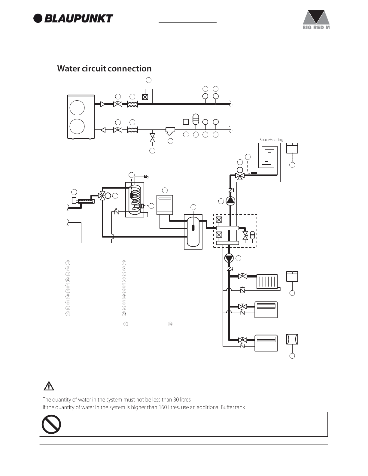
3.5 Water circuit connection
3.6 Electrical connections
3.7 Remote controller
4. Remote controller ........................................................ 26
4.1 Buttons
4.2 Display panel
5. Operation and functions
of the Remote controller .......................................... 28
5.1 System ON/OFF
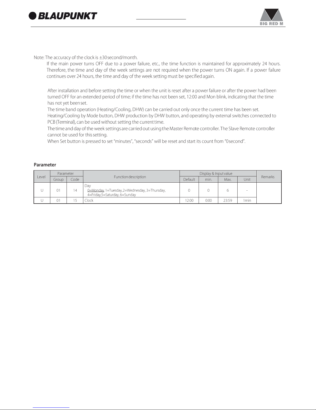
5.2 Setting the day and time
5.3 Selecting the operating mode
5.4 Domestic Hot Water production
5.5 Setting the time bands for Heating/Cooling
5.6 Setting the time bands for DHW, Low tariff and Night mode
5.7 Procedure for accessing the Parameter setting menu
6. Electrical connections ............................................... 49
6.1 PCB(Terminal)
6.2 PCB(Terminal) Input/Output
6.3 Parameters Input/Output
7. Unit Management........................................................ 53
7.1 Operating modes
7.1.1 Select mode from user interface
7.1.2 Select mode by remote contact
7.2 Water temperature set point
7.2.1 Fixed set point
7.2.2 Climatic curve
7.2.2.1 Heating Climatic curves
7.2.2.2 Cooling Climatic curves
7.2.3 Additional Outdoor air temperature probe for Climatic
curves
7.2.4 Buffer tank temperature probe
7.2.5 HP unit control
7.2.5.1 HP unit controlled based on Outgoing water temperature
7.2.5.2 HP unit controlled based on Outgoing water temperature
and Room air temperature
7.2.5.3 HP unit controlled based on Buffer tank temperature
7.2.5.4 HP unit controlled based on Buffer tank temperature
and Room air temperature
7.2.5.5 HP unit controlled based on DHW tank temperature
7.3 Water pump management
7.3.1 Main water pump
7.3.1.1 Continuous operation “Always ON”
7.3.1.2 Sniffing operation “Sniffing cycle”
7.3.1.3 Unlock pump function
7.3.1.4 Pump output adjustment function
7.4 Frost protection
7.4.1 Frost protection based on Room air temperature
7.4.2 Frost protection based on Outdoor air temperature
7.4.3 Frost protection based on Outgoing water temperature
7.4.4 DHW tank frost protection
7.4.5 Secondary system circuit frost protection
7.5 Input/Output contact
7.5.1 Heating/Cooling mode remote contact
7.5.2 ON/OFF DHW production remote contact
7.5.3 ON/OFF remote contact
7.5.4 EHS Alarm
7.5.5 Flow switch
7.5.6 Dual set point control
7.5.7 Additional water pump
7.5.7.1 Additional water pump1
7.5.7.2 Additional water pump2
7.5.8 Heating/Cooling mode output
7.5.9 Configurable contact (Alarm)
7.5.9.1 Alarm
7.5.9.2 Ambient temperature reached
7.5.10 Night mode
7.5.11 Low tariff
7.5.12 Dehumidifier management
7.5.13 Space Heating management
8. Domestic Hot Water Production .......................... 98
8.1 DHW 3way valve management
8.1.1 Max time for DHW request
8.1.2 DHW 3way valve change over time
8.2 DHW production mode
8.2.1 Heat pump only
8.2.2 DHW Electric heater only
8.2.3 Heat pump + DHW heater
8.2.4 Legionella prevention function
8.3 Backup heater
8.3.1 Backup heater in Replacement mode
8.3.2 Backup heater in Supplementary mode
8.3.3 Freeze protection function
8.4 EHS (External heat source)
8.4.1 EHS in Replacement mode
8.4.2 EHS in Supplementary mode
9. Parameter List ............................................................. 124
9.1 Access limitation
9.2 Parameter table
10. Installation check and Test operation ............ 138
10.1 Installation check
10.2 Test operation
11. Service and Maintenance .................................... 140
11.1 1 Error code display
11.2 2 Error history display
11.3 3 Method of reset error code display
11.4 List of Error codes
11.5 Check and troubleshooting
11.6 6 Monitor display function
11.7 7 Maintenance
Page 3
3
1. Responsibility and recommendations
www.blaupunkt.com
1. RESPONSIBILITY AND RECOMMENDATIONS
Page 4
1. Responsibility and recommendations
4
www.blaupunkt.com
Page 5
1. Responsibility and recommendations
5
www.blaupunkt.com
Proh
CAUTION
Page 6
1. Responsibility and recommendations
6
www.blaupunkt.com
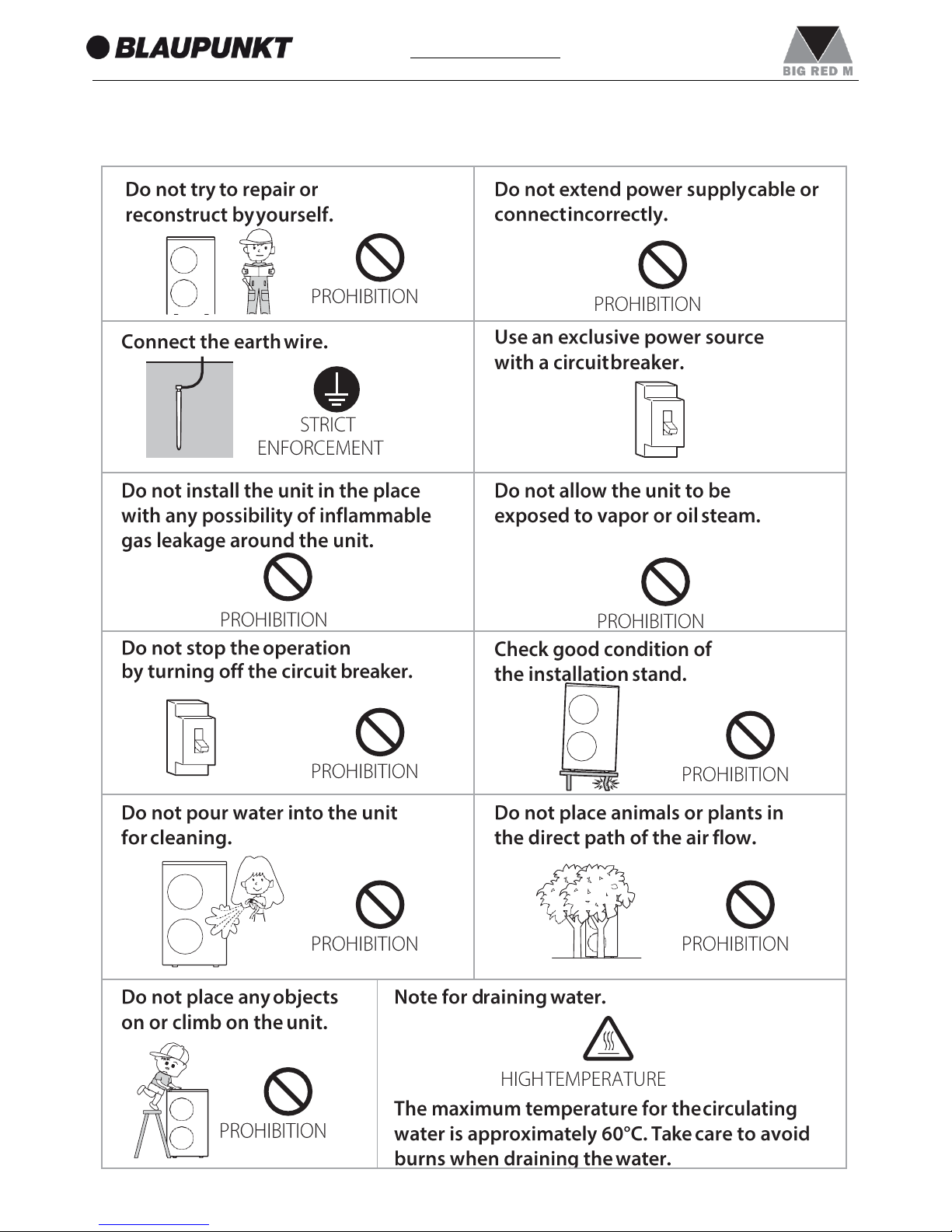
Hight temperature
Page 7
1. Responsibility and recommendations
7
www.blaupunkt.com
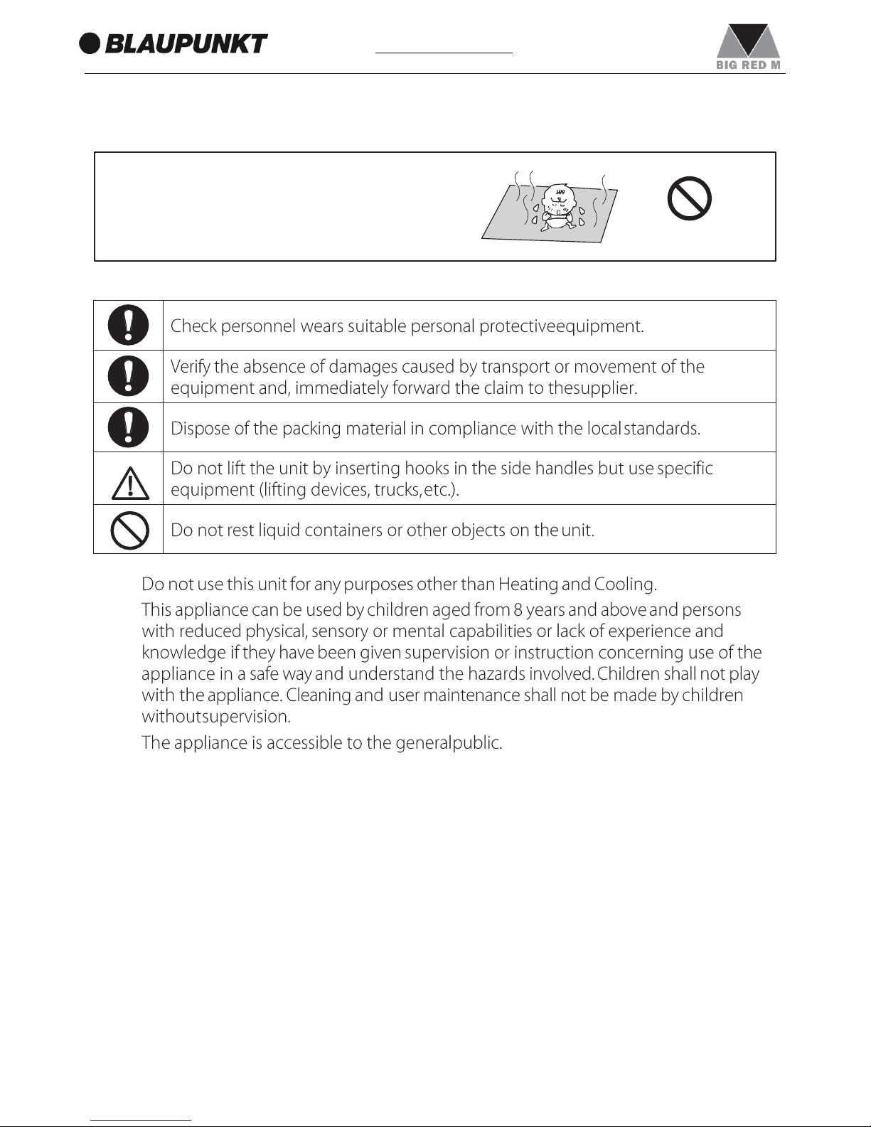
If the same part of the body is
exposed to the floor heating for
a long time, it could cause low
temperature scalding.
PROHIBITION
Page 8
1. Responsibility and recommendations
8
www.blaupunkt.com
1.
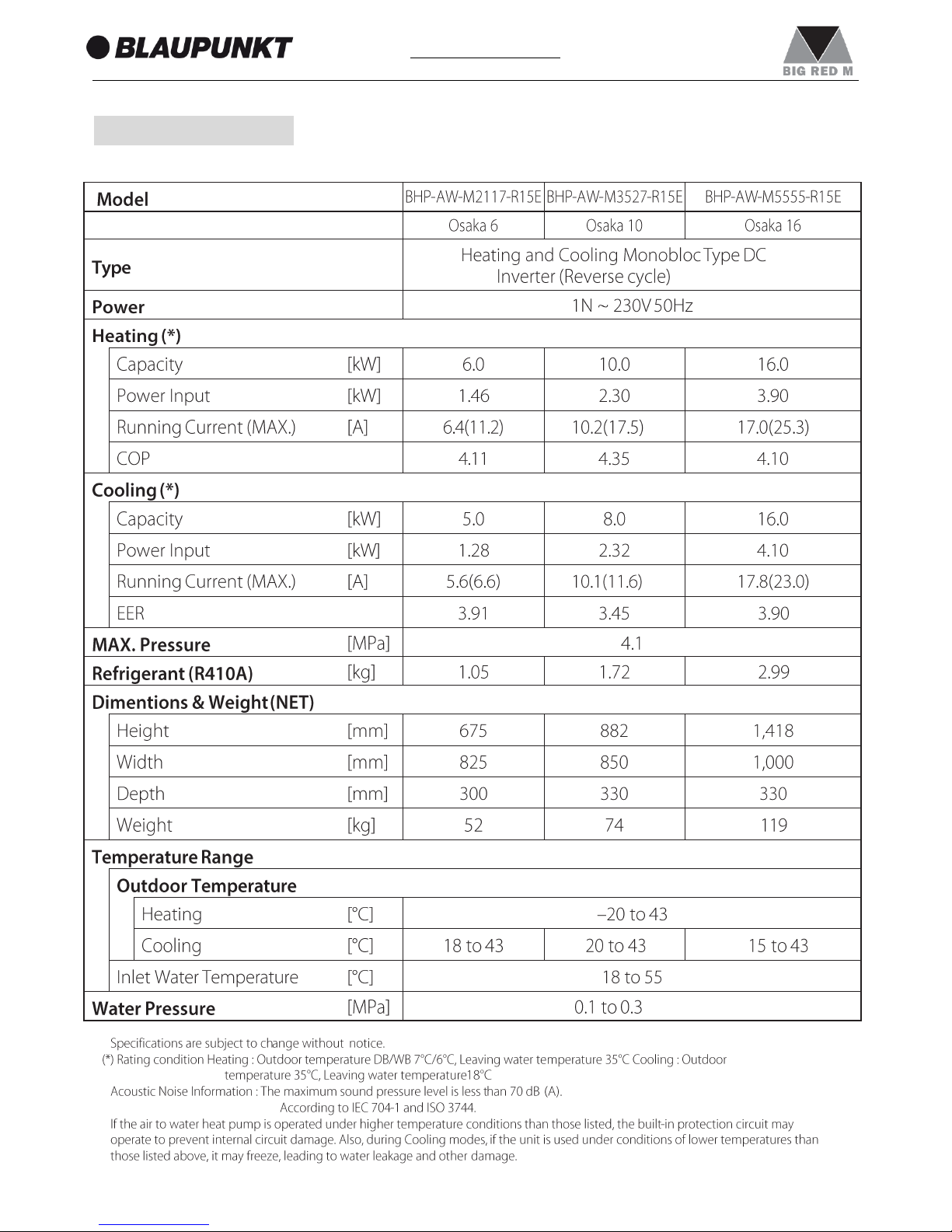
2. SPECIFICATIONS
•
•
•
Page 9
1. Responsibility and recommendations
9
www.blaupunkt.com
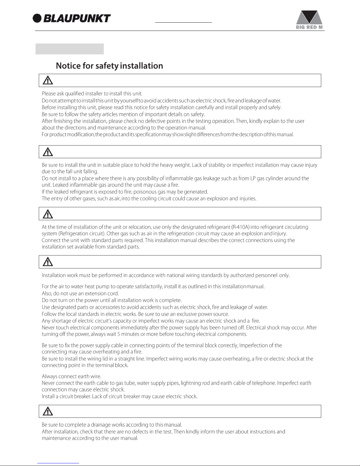
3. INSTALLATION
3.1
•
•
•
•
•
•
•
•
•
•
•
•
•
•
•
•
•
•
•
•
•
•
•
•
•
•
CAUTION
DANGER
WARNING
DANGER
CAUTION
Page 10
10
1. Responsibility and recommendations
www.blaupunkt.com
R3/4(20A)
R1(25A)
R1(25A)
R1 1/4(32A)
R1 1/4(32A)
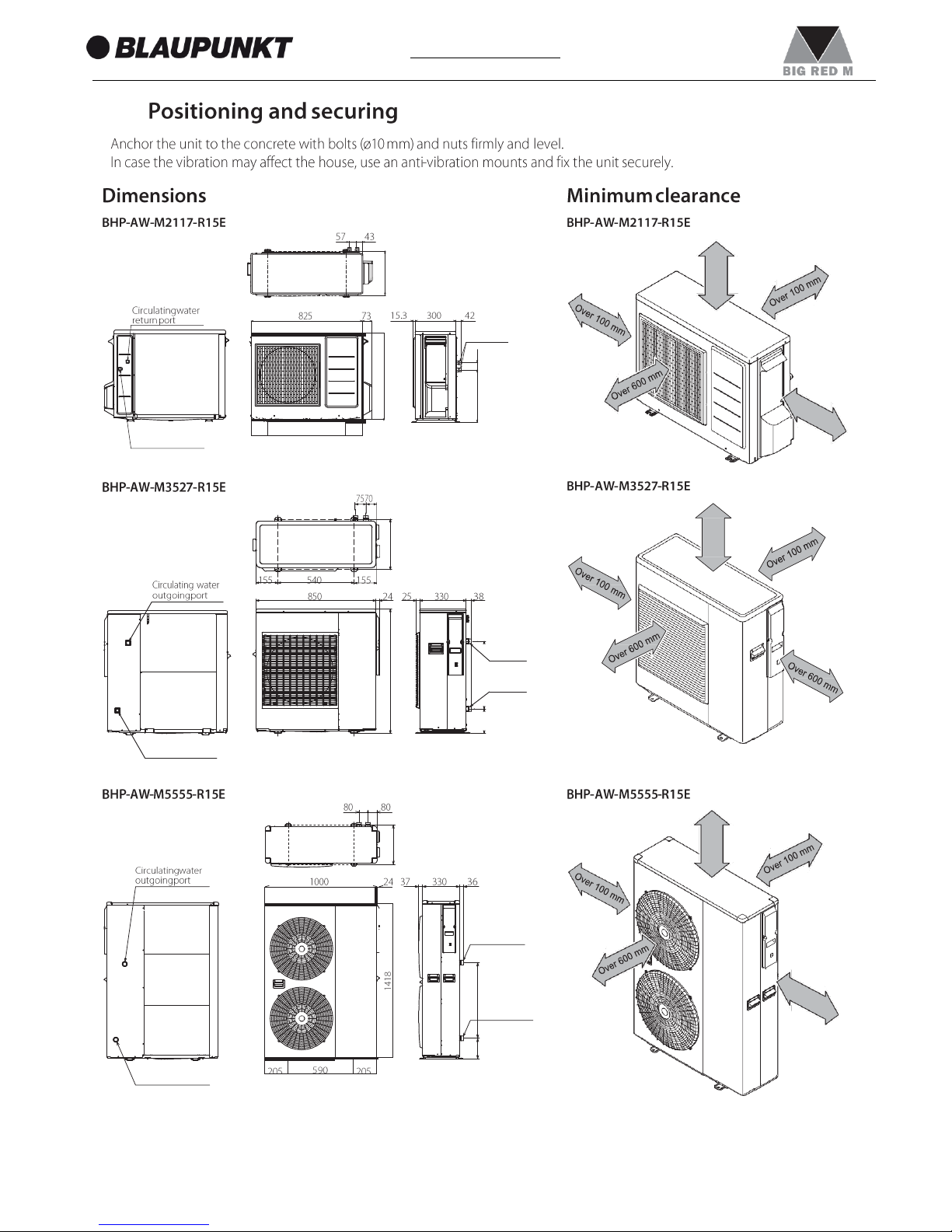
3.2
•
•
Circulating water
return port
Circulating water
outgoing port
Circulating water
return port
327
882
357
357
388
54
173
480
O
v
er
300
mm
O
v
er
300
mm
O
v
er
300
mm
675
Page 11
11
1. Responsibility and recommendations
www.blaupunkt.com
•
•
•
•
•
•
•
•
(1)
(2)
(3)
(4)
(5)
(6)
(7)
•
•
CAUTION
DANGER
Page 12
12
1. Responsibility and recommendations
www.blaupunkt.com
Wiring lid
Air outlet
Screw
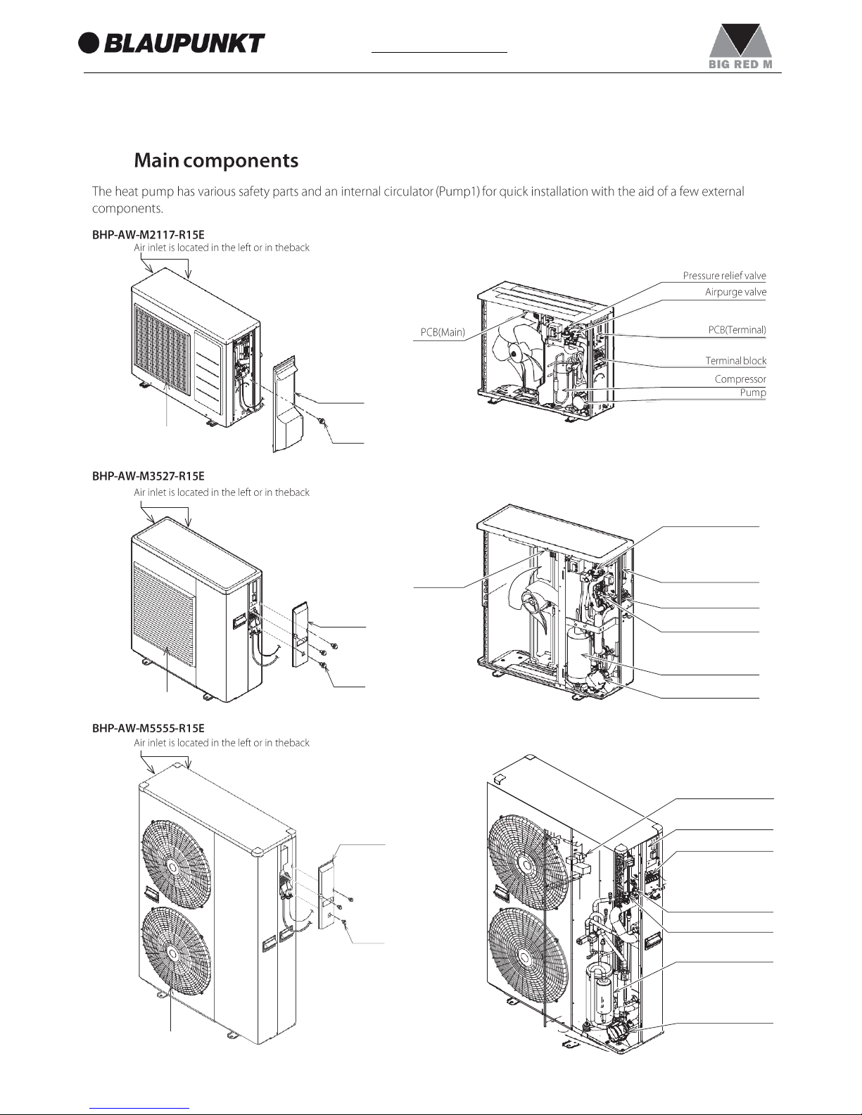
3.3
PCB (Main)
PCB (Terminal)
Terminal block
Pressure relief valve
Airpurge valve
Compressor
Pump
Wiring lid
Screw
Air outlet
Airpurge valve
PCB(Main)
PCB(Terminal)
Terminal block
Pressure relief valve
Compressor
Pump
Wiring lid
Screw
Air outlet
Page 13
13
1. Responsibility and recommendations
www.blaupunkt.com
Level3
Level2
Level1
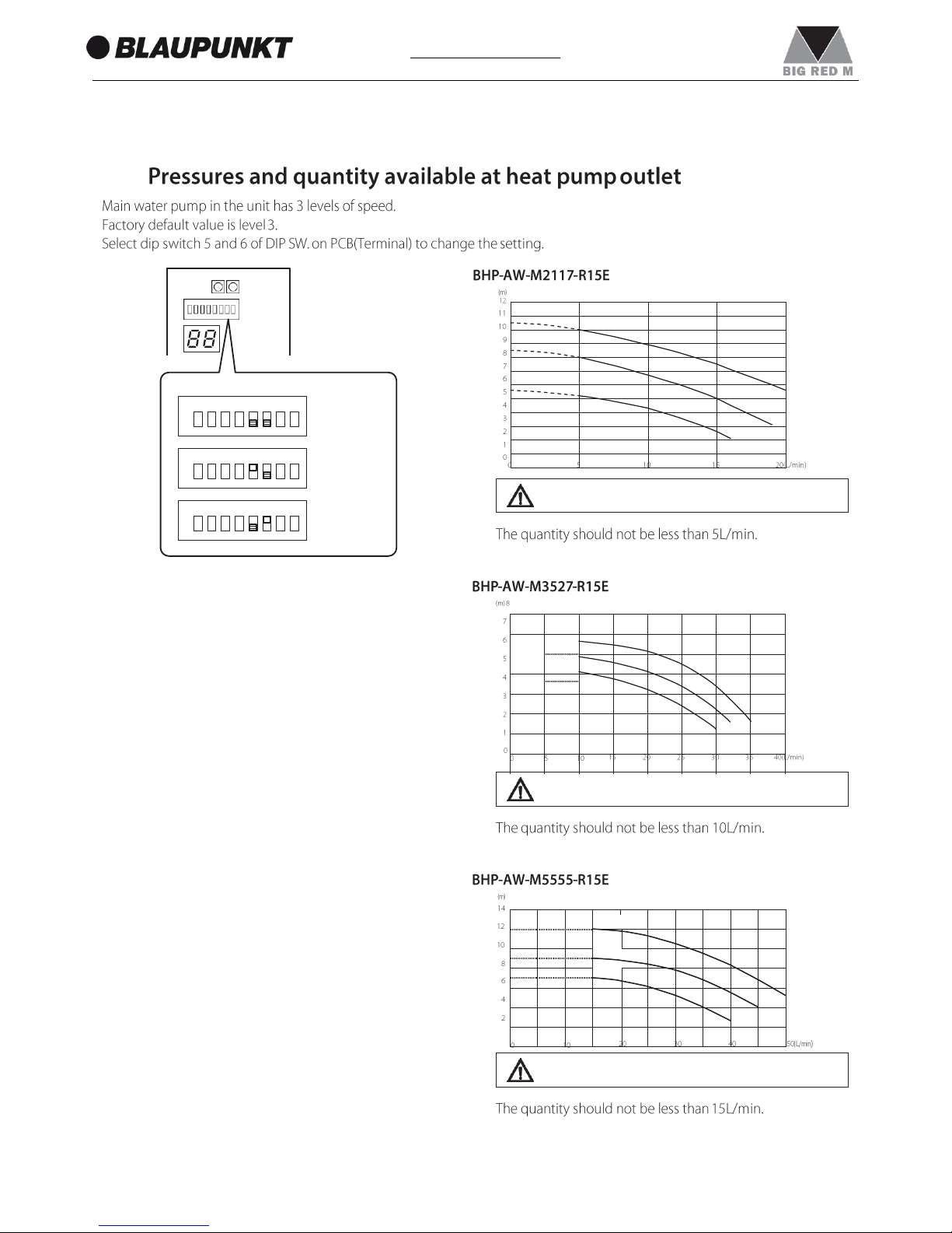
3.4
CAUTION
CAUTION
CAUTION
DIP SW.
5
Level 3
(Maximum)
5
Level 2
(Medium)
5
Level 1
(Minimum)
Level3
Level2
Level1
Level3
Level2
Level1
Level3
Level2
Level1
ON 1 2 3 4
6
7 8
OFF
ON 1 2 3 4
6
7 8
OFF
ON 1 2 3 4
6
7 8
OFF
Page 14
14
1. Responsibility and recommendations
www.blaupunkt.com
Outlet
1
2
8 9
P T
Inlet
1
2
F P T
7 8 9
HP unit
5
4
3.5
•
•
Do not use the heat pump to treat industrial process water, swimming pool water or domestic water.
Set-up an intermediate heat exchanger for all the above cases.
CAUTION
18
17
M
12
10
14
M
11
16
13
15
DHW tank
Mani fold
Buffer tank
16
Shut-off valve
Vibration damper joint
Air bleed valve
Fill/drain valve
Water line filter
Flow switch
Expansion vessel
Pressure gauge
Thermometer
Backup heater*
DHW 3way valve
DHW tank temperature probe
DHW Electric heater
EHS*
Buffer tank temperature probe
Additional water pump
Mixing valve
Mix water temperature probe
Remote controller
Humidity sensor
Radiant panel
Fan convector
* Backup heater and EHS
cannot be used at same time.
Dehumidifier
6 3
19
19
20
Page 15
15
1. Responsibility and recommendations
www.blaupunkt.com
1.
2.
3.
4.
5.
6.
7.
8.
9.
Page 16
16
1. Responsibility and recommendations
www.blaupunkt.com
•
•
•
•
•
•
•
•
•
•
•
•
•
•
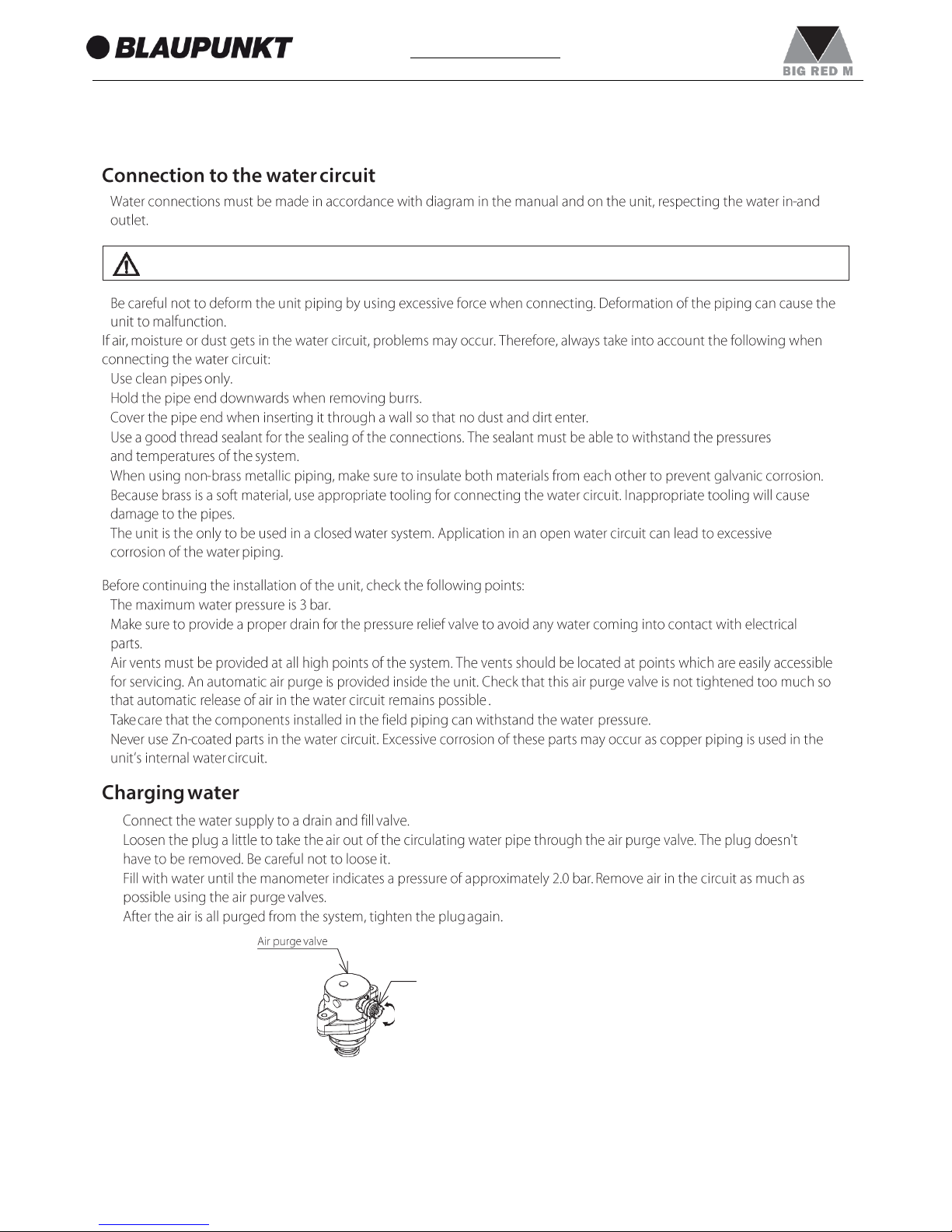
1)
2)
3)
4)
Plug
loosen
tighten
CAUTION
Page 17
17
1. Responsibility and recommendations
www.blaupunkt.com
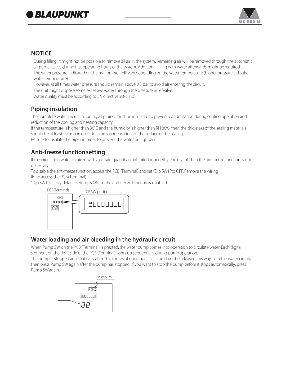
ON 1 2 3 4 5 6 7 8
OFF
•
•
•
•
Display
Page 18
18
1. Responsibility and recommendations
www.blaupunkt.com
Hose
•
•
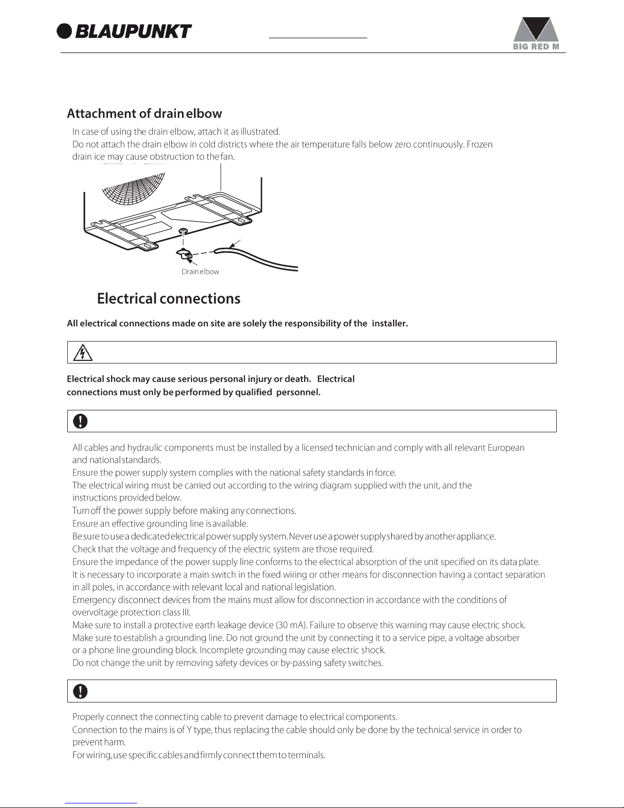
3.6
•
•
•
•
•
•
•
•
•
•
•
•
•
•
•
•
ATTENTION
DANGER
DANGER
Page 19
19
1. Responsibility and recommendations
www.blaupunkt.com
•
•
•
•
•
•
•
•
•
•
•
•
CAUTION
WARNING
CAUTION
Page 20
20
1. Responsibility and recommendations
www.blaupunkt.com
Sleeve
Sleeve
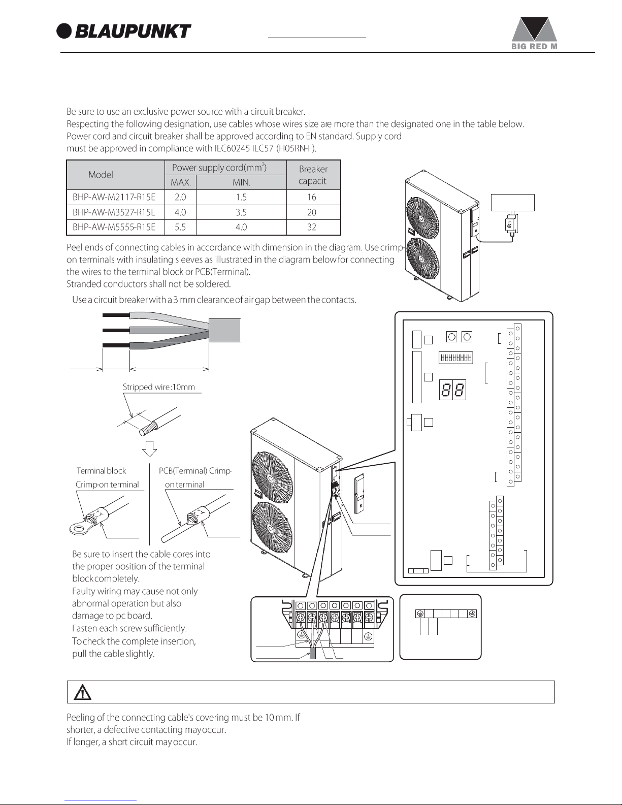
•
•
•
•
•
CAUTION
10 mm
30 mm
POW
ER
Terminal block
Cable clamp
N
Earth wire
Power supply cord
(L) (N)
2
Reset Pump
SW. SW.
17
Remote 1
Humidity
Sensor
4
Controller
18 COM
2
DHW Remote
ON
OFF
GND 3
24VAC 4
COM 5
3
3-way
mixing
valve
Control 6
DHW 7
T.probe 8
OUTDOOR 9
T.probe
10
BUFFER 11
T.probe
12
Mix water
13
T.probe
14
Contact
20
ON/OFF
or
21
EHS Alarm
22
Dual Set
Point
23 Control
24
Heating
Cooling
25 mode
26 Flow
27 switch
28 Night
29 mode
30
Low
tariff
PCB
(TERMINAL)
+
15
RS485
-
16
31
32
RS485
GND
45 Dehumidifier
Neutral N
41
42
46
Electric heater
EHS
Heating
r
47
Alarm
48 Pump1
Cooling 43
1
3-way
valve
output 44
Phase 51
mode
Signal 52
49 Pump2
50 Neutral
N.C.
Connection diagrams
Unit side terminal
Earth
(L) (N)
Power supply
Distribution
board
Circuit
breaker
3
2 1 L
L N 1
2
3
Page 21
21
1. Responsibility and recommendations
www.blaupunkt.com
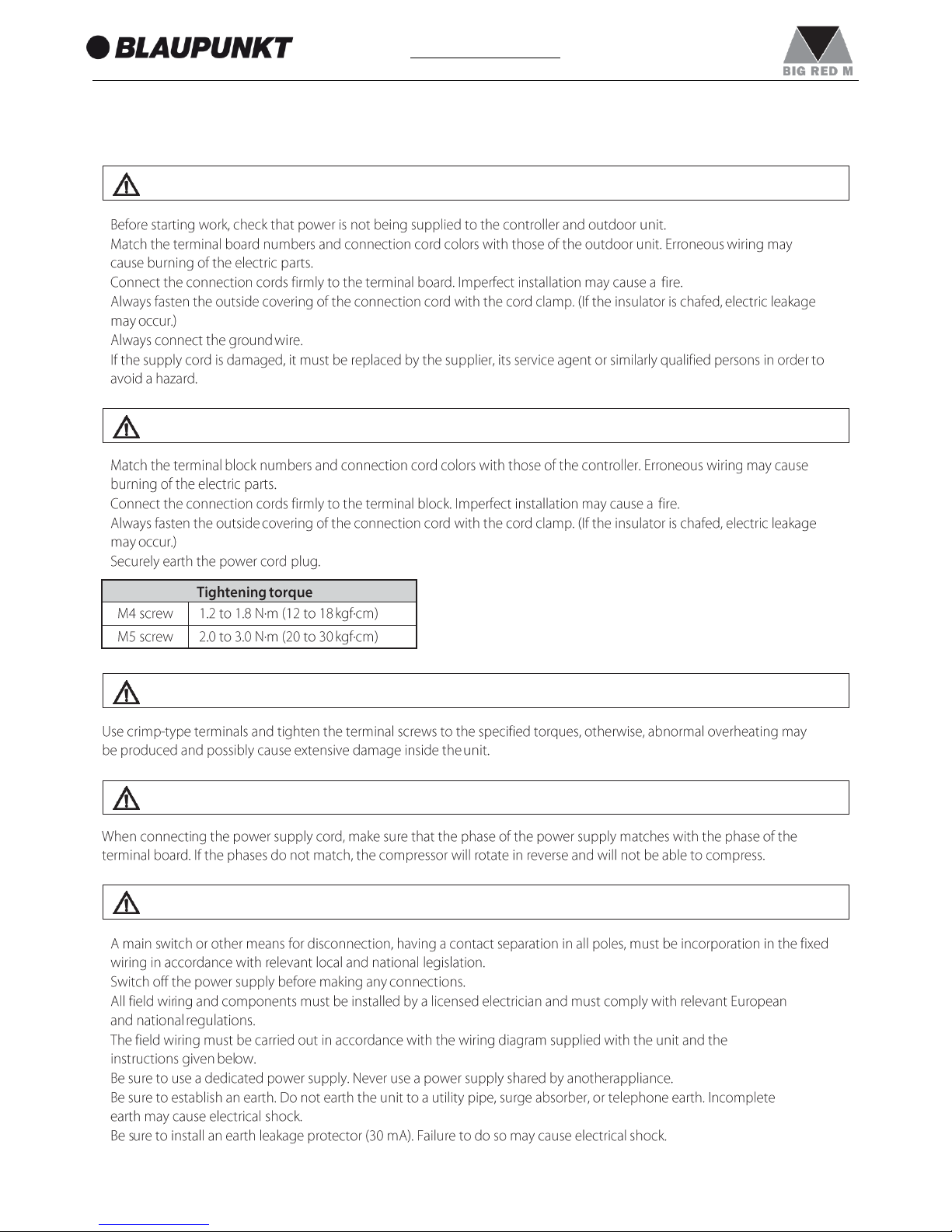
•
•
•
•
•
•
•
•
•
•
•
•
•
•
•
•
•
WARNING
CAUTION
WARNING
CAUTION
WARNING
Page 22
22
1. Responsibility and recommendations
www.blaupunkt.com
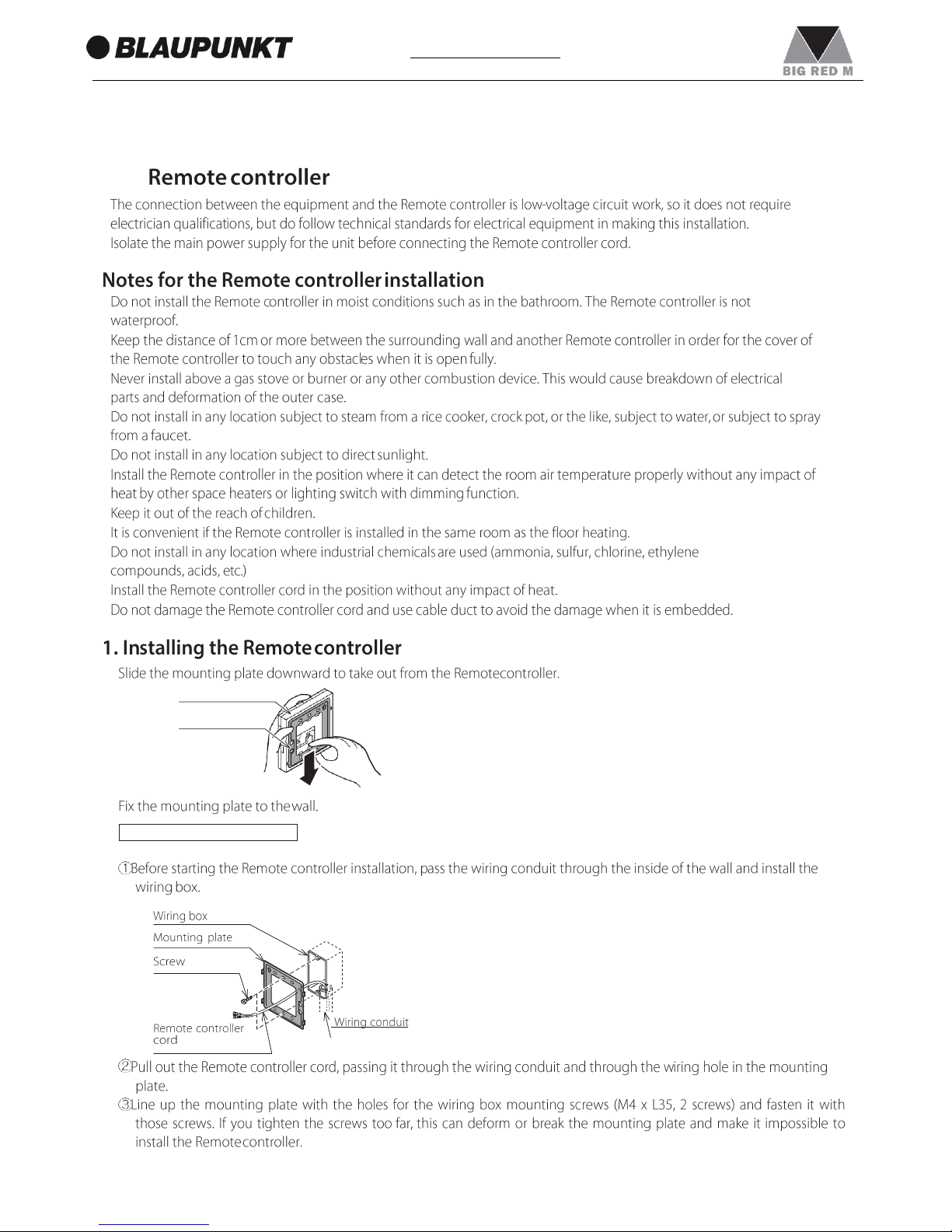
3.7
•
•
•
•
•
•
•
•
•
•
•
•
•
1.
2.
When the wiring is embedded
Remote controller
Mounting plate
Page 23
23
1. Responsibility and recommendations
www.blaupunkt.com
•
3.
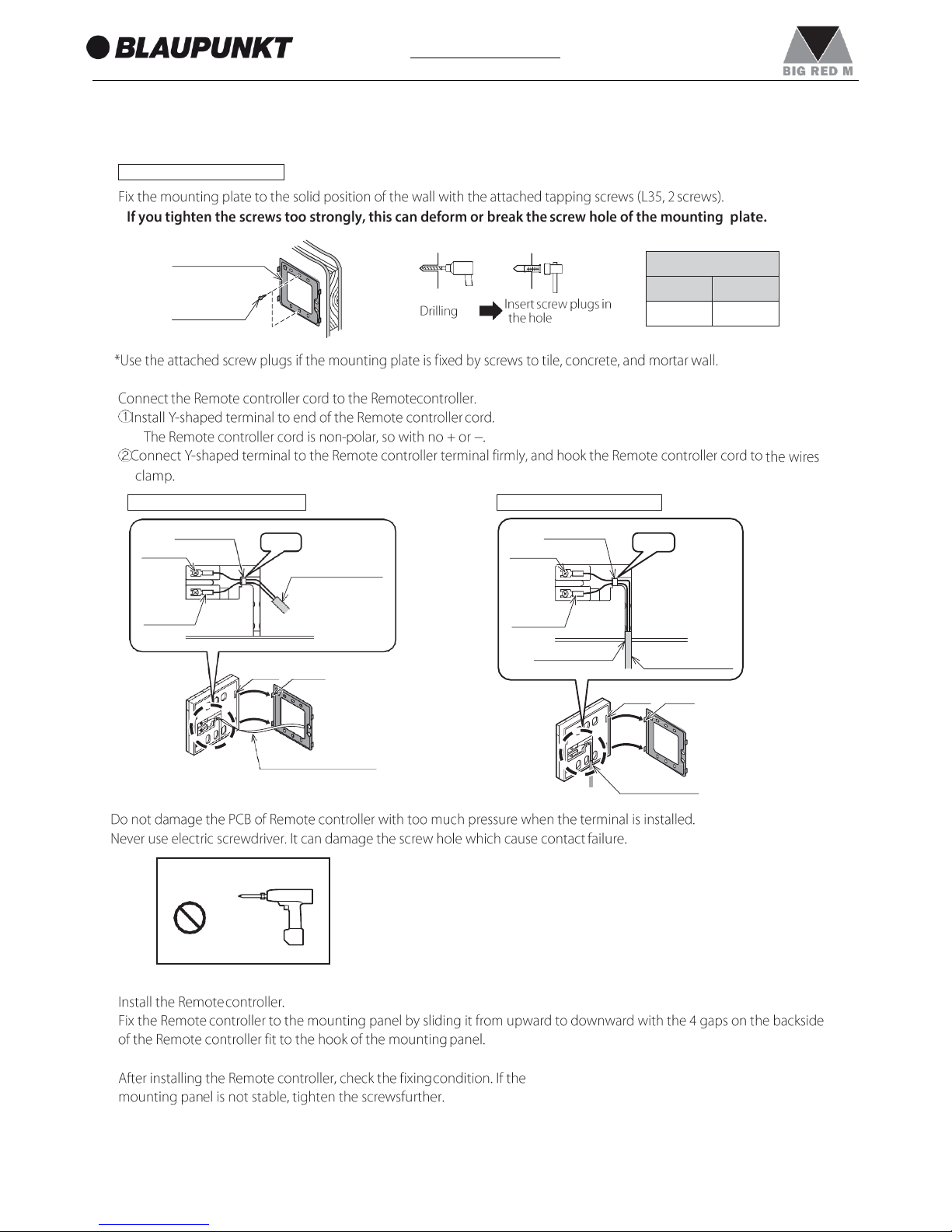
•
•
•
4.
5.
Never use electric driver
wires clamp
terminal
Hook
Y-shaped
terminal
knock out hole
Remote controller
cord
gaps
hooks
knock out hole
wires clamp
terminal
Hook
Remote controller
cord
Y-shaped
terminal
gaps
hooks
Remote controller cord
When the wiring is exposed
When the wiring is embedded
When the wiring is exposed
Mounting plate
Screw
Pilot hole
diameter
depth
6mm
30mm
Page 24
24
1. Responsibility and recommendations
www.blaupunkt.com
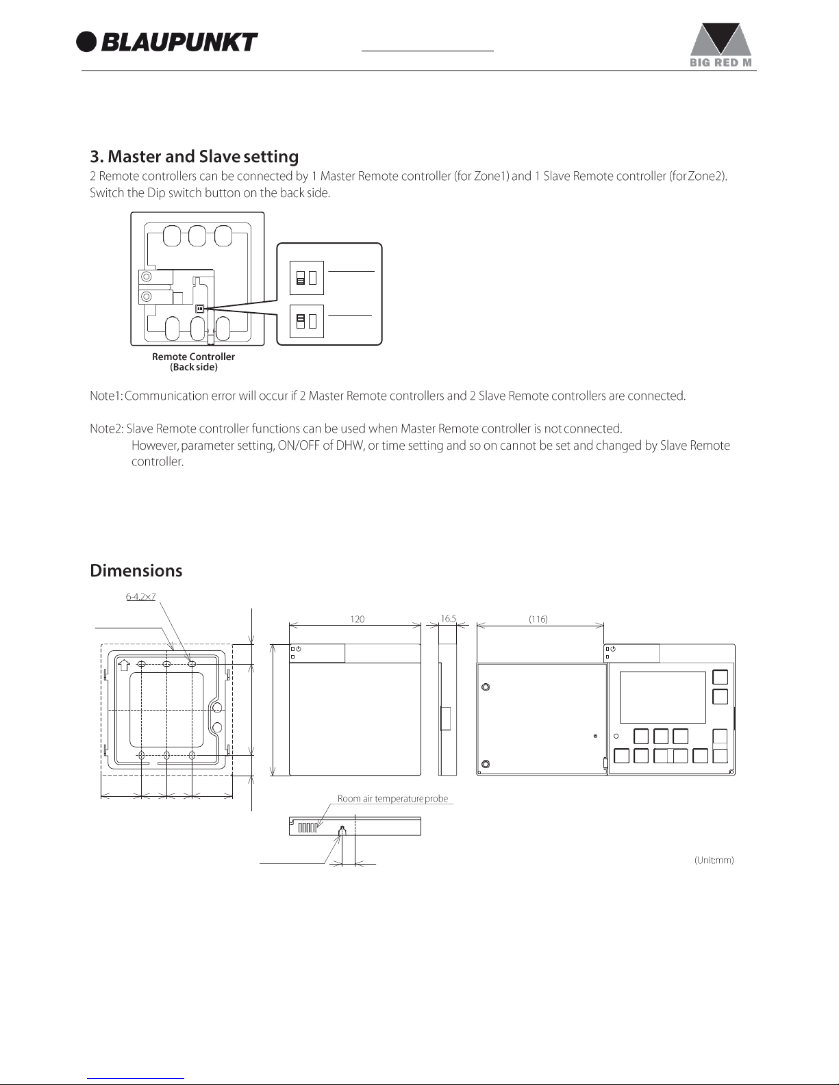
1.
2.
3.
4.
5.
•
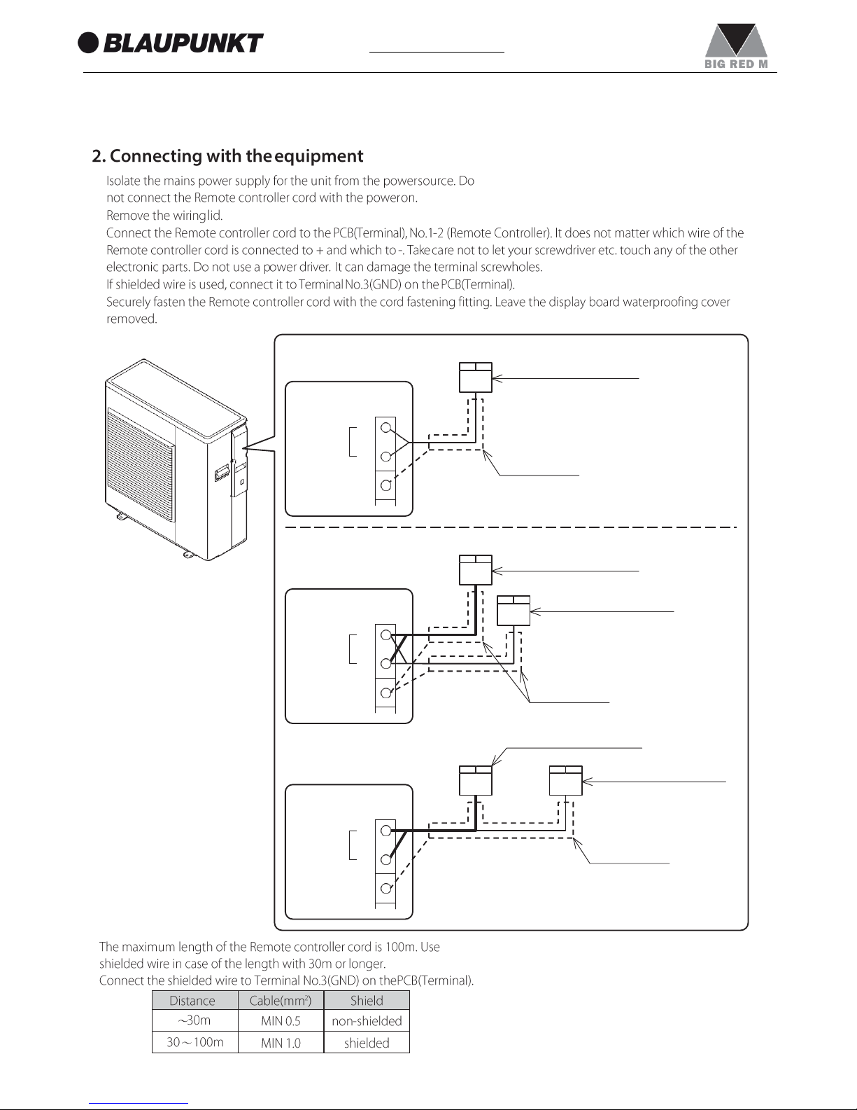
1 Remote controller
Master Remote controller
PCB(Terminal)
Remote
1
Controller
2
Shielded cable
GND 3
2 Remote controller
Master Remote controller
PCB(Terminal)
Slave Remote controller
Remote
Controller
1
2
GND 3
Shielded cable
Master Remote controller
Slave Remote controller
PCB(Terminal)
Remote
Controller
1
2
Shielded cable
GND 3
Page 25
25
1. Responsibility and recommendations
www.blaupunkt.com
Mounting plate
37
23 23
37
DIP SW
SW1=OFF
Master
for Zone1
SW1=ON
Slave
for Zone2
ON
1 2
ON
1 2
Knock out hole
12
18.25
83.5
18.25
120
Page 26
26
1. Responsibility and recommendations
www.blaupunkt.com
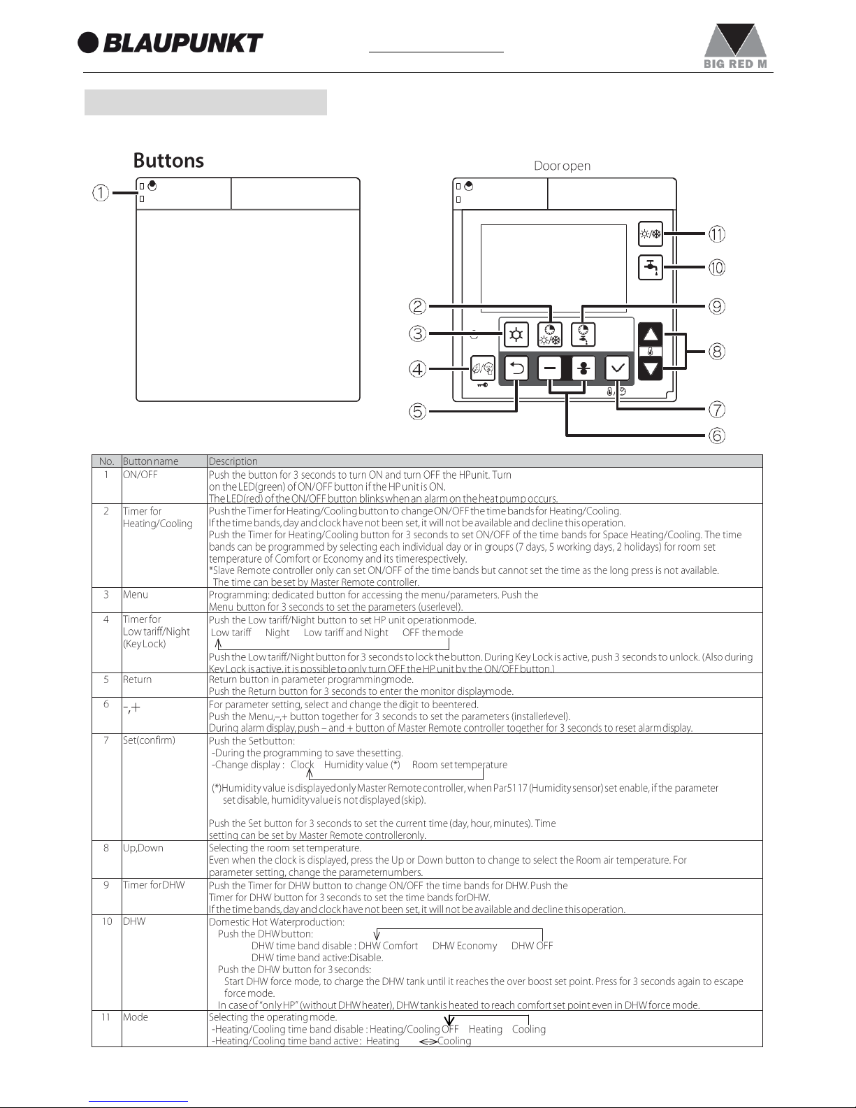
4. REMOTE CONTROLLER
4.1
→ → →
→ →
-
→ →
-
→ →
Page 27
27
1. Responsibility and recommendations
www.blaupunkt.com
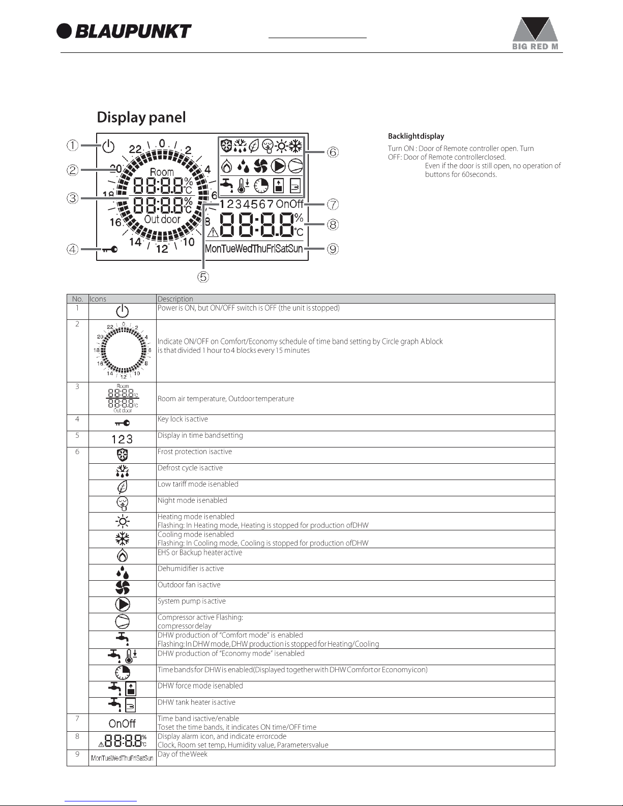
4.2
•
Page 28
28
1. Responsibility and recommendations
www.blaupunkt.com
5. OPERATION AND FUNCTIONS OF THE REMOTE CONTROLLER
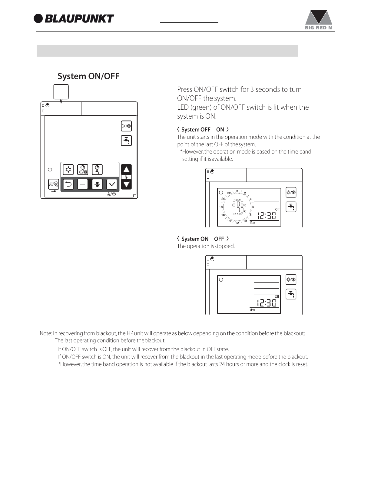
5.1
→
→
•
•
1
3 seconds
1
Page 29
29
1. Responsibility and recommendations
www.blaupunkt.com
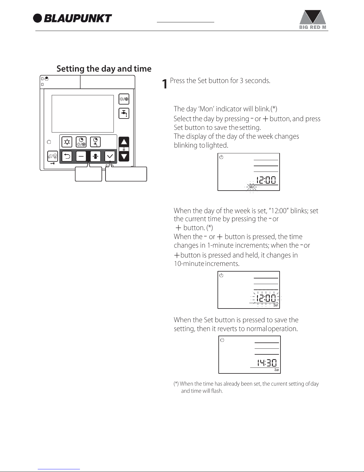
5.2
2・3 1・2・3
2 3
Page 30
30
1. Responsibility and recommendations
www.blaupunkt.com
•
•
•
•
Page 31

31
1. Responsibility and recommendations
www.blaupunkt.com
5.3
→ →
1
1
Page 32

32
1. Responsibility and recommendations
www.blaupunkt.com
1)
2)
3)
2
2
Page 33

33
1. Responsibility and recommendations
www.blaupunkt.com
5.4
→ →
→
→
→
1
2
1 2 3
Page 34

34
1. Responsibility and recommendations
www.blaupunkt.com
5.5
1
1
Page 35

35
1. Responsibility and recommendations
www.blaupunkt.com
→ →
3 seconds
1
2・3 2・3
1 2 3
Page 36

36
1. Responsibility and recommendations
www.blaupunkt.com
4 4
4
Page 37

37
1. Responsibility and recommendations
www.blaupunkt.com
5・6 5・6
5
6
Page 38

38
1. Responsibility and recommendations
www.blaupunkt.com
7
7 8 9
Page 39

39
1. Responsibility and recommendations
www.blaupunkt.com
Comfort:20℃
Economy:18℃
Page 40

40
1. Responsibility and recommendations
www.blaupunkt.com
5.6
3 seconds
1
2
1・2
1
2
Page 41

41
1. Responsibility and recommendations
www.blaupunkt.com
3 3
3
Page 42

42
1. Responsibility and recommendations
www.blaupunkt.com
4・5 4・5・6
4 5 6
Page 43

43
1. Responsibility and recommendations
www.blaupunkt.com
7 8
Page 44

44
1. Responsibility and recommendations
www.blaupunkt.com
1st
2nd
3rd
1st
1st
2nd
DHW set temperature
50°C
40°C
DHW time band Comfort 50°C
Economy 40°C
ON
OFF
ON OFF
ON
OFF
2nd
ON
50°C
OFF
ON OFF
Low tariff time band
Night mode time band
ON
OFF
ON
OFF
Page 45

45
1. Responsibility and recommendations
www.blaupunkt.com
5.7
3 seconds
1
2 2
2
Page 46

46
1. Responsibility and recommendations
www.blaupunkt.com
3
3
3
Page 47

47
1. Responsibility and recommendations
www.blaupunkt.com
3 seconds
6
4 5
4・5
4 5 6
Page 48

48
1. Responsibility and recommendations
www.blaupunkt.com
3 seconds
1・4
1・4
2 2
2 3 4
Page 49

49
1. Responsibility and recommendations
www.blaupunkt.com
Reset Pump
SW. SW.
17
Remote
4
Controller
1
2
Humidity
Sensor
18 COM
DHW Remote
ON
OFF
GND 3
24VAC 4
3-way
mixing
COM 5
3
valve
Control 6
DHW 7
T.probe 8
Contact
20
ON/OFF
or
21
EHS Alarm
22
Dual Set
Point
23 Control
24
Heating
Cooling
25 mode
2
OUTDOOR 9
T.probe 10
BUFFER 11
26 Flow T.probe
12
Mix water 13
T.probe
14
27
switch
28
Night
29
mode
Low
PCB
(TERMINAL)
RS485
+
15
-
16
31
32
tariff
RS485
GND
45 Dehumidifier
Neutral N
46
Electric heater
41
EHS
42
Heating
47
Alarm
48 Pump1
Cooling 43
mode
49 Pump2
50 Neutral
1
3-way
valve
output 44
Phase 51
Signal 52
N.C.
6. ELECTRICAL CONNECTIONS
6.1
Page 50

50
1. Responsibility and recommendations
www.blaupunkt.com
6.2
-
-
Page 51

51
1. Responsibility and recommendations
www.blaupunkt.com
6.3
→
→
Page 52

52
1. Responsibility and recommendations
www.blaupunkt.com
Page 53

53
1. Responsibility and recommendations
www.blaupunkt.com
7. UNIT MANAGEMENT
7.1
7.1.1
7.1.2
PCB(Terminal)
24 Heating
Cooling
25
mode
Page 54

54
1. Responsibility and recommendations
www.blaupunkt.com
7.2
7.2.1
Page 55

55
1. Responsibility and recommendations
www.blaupunkt.com
(Selected by Par5109)
7.2.2
7.2.2.1
Page 56

56
1. Responsibility and recommendations
www.blaupunkt.com
(Selected by Par5109)
7.2.2.2
Page 57

57
1. Responsibility and recommendations
www.blaupunkt.com
N
N-W
7.2.3
8.4.1
8.4.2
Distance
Cable(mm2)
30m
MIN 0.5
30 100m
MIN 1.0
Additional probe
Outdoor air temperature
PCB(Terminal)
On board probe
Outdoor air temperature
OUTDOOR
9
10
T.probe
H
1/2H
min2.5m
Page 58

58
1. Responsibility and recommendations
www.blaupunkt.com
7.2.4
→
→
→
→
PCB(Terminal)
BUFFER
11
Buffer tank temperature probe
T.probe 12
Buffer tank
Page 59

59
1. Responsibility and recommendations
www.blaupunkt.com
7.2.5
1)
2)
3)
4)
5)
-
-
→
→
Page 60

60
1. Responsibility and recommendations
www.blaupunkt.com
7.2.5.1
→
7.2.5.2
→
→
Page 61

61
1. Responsibility and recommendations
www.blaupunkt.com
7.2.5.3
→
Page 62

62
1. Responsibility and recommendations
www.blaupunkt.com
7.2.5.4
→
→
Page 63

63
1. Responsibility and recommendations
www.blaupunkt.com
7.2.5.5
→
Page 64

64
1. Responsibility and recommendations
www.blaupunkt.com
Heat pump ON
OFF
Maximum
Compressor (Hz)
minimum
OFF
set temp. + 1
Water set temp. (°C)
set temp. - 1
set temp. - Hysteresis
Heating ON
Water temperature is stable
Comp. OFF Comp. OFF → ON
set point + 1°C
× 3min
Heat pump ON
OFF
Maximum
Compressor (Hz)
minimum
OFF
set temp. + Hysteresis
set temp. +1
Water set temp. (°C)
set temp. -1
Cooling ON
Water temperature is stable
Comp. OFF Comp. OFF → ON
set point - 1°C
× 3min
Page 65

65
1. Responsibility and recommendations
www.blaupunkt.com
7.3
7.3.1
→
→
7.3.1.1
7.3.1.2
Page 66

66
1. Responsibility and recommendations
www.blaupunkt.com
→
→
7.3.1.3
(5sec)
Water temp. detect
(3min)
(5min)
(3min)
Page 67

67
1. Responsibility and recommendations
www.blaupunkt.com
Level3
Level2
Level1
7.3.1.4
CAUTION
CAUTION
CAUTION
Level3
Level2
Level1
DIP SW.
Level 3
(Maximum)
Level 2
(Medium)
Level 1
(Minimum)
Level3
Level2
Level1
Level3
Level2
Level1
ON 1 2 3 4 5 6 7 8
OFF
ON 1 2 3 4 5 6 7 8
OFF
ON 1 2 3 4 5 6 7 8
OFF
Page 68

68
1. Responsibility and recommendations
www.blaupunkt.com
7.4
7.4.1
(1.0°C)
Water pump deactivation
hysteresis
Page 69

69
1. Responsibility and recommendations
www.blaupunkt.com
7.4.2
(3.0°C)
Water pump deactivation
hysteresis
(3.0°C)
Backup heater
hysteresis
Page 70

70
1. Responsibility and recommendations
www.blaupunkt.com
7.4.3
(3.0°C)
Water pump deactivation
hysteresis
(3.0°C)
Backup heater
hysteresis
Page 71

71
1. Responsibility and recommendations
www.blaupunkt.com
7.4.4
7.4.5
(3.0°C)
DHW Electric heater
hysteresis
Page 72

72
1. Responsibility and recommendations
www.blaupunkt.com
7.5
7.5.1
PCB(Terminal)
24 Heating
Cooling
25
mode
Page 73

73
1. Responsibility and recommendations
www.blaupunkt.com
7.5.2
PCB(Terminal)
18 COM
DHW Remote
Contact
Page 74

74
1. Responsibility and recommendations
www.blaupunkt.com
→
→
→
→
→
→
→
→
→
→
→
→→→
→
→
Page 75

75
1. Responsibility and recommendations
www.blaupunkt.com
7.5.3
→→→
→
→
→
PCB(Terminal)
20
ON/OFF
or
21
EHS Alarm
Page 76

76
1. Responsibility and recommendations
www.blaupunkt.com
→ →
DHW has priority than
Heating/Cooling
Heating
DHW
Heating
DHW
Page 77

77
1. Responsibility and recommendations
www.blaupunkt.com
7.5.4
PCB(Terminal)
20
ON/OFF
or
21
EHS Alarm
Page 78

78
1. Responsibility and recommendations
www.blaupunkt.com
7.5.5
PCB(Terminal)
26
Flow
27
switch
Page 79

79
1. Responsibility and recommendations
www.blaupunkt.com
7.5.6
PCB(Terminal)
22 Dual Set
Point
23
Control
Page 80

80
1. Responsibility and recommendations
www.blaupunkt.com
7.5.7
-
-
7.5.7.1
PCB(Terminal)
230V 50Hz
45 Dehumidifier
Neutral N
41
EHS
46
Electric
heater
47
Alarm
42
48 Pump1
Additional water pump1
Heating
Cooling
mode
output
43
P
49
Pump2
44
Page 81

81
1. Responsibility and recommendations
www.blaupunkt.com
HP unit
Space Heating
M 3way valve
Buffer tank
Pump 1
HP unit
Space Heating
M 3way valve
Pump 1
Page 82

82
1. Responsibility and recommendations
www.blaupunkt.com
7.5.7.2
PCB(Terminal)
230V 50Hz
45 Dehumidifier
Neutral N
41
EHS
46
Electric
heater
47
Alarm
42
48 Pump1
Additional water pump2
Heating
Cooling
mode
output
43
P
49
Pump2
44
Page 83

83
1. Responsibility and recommendations
www.blaupunkt.com
HP unit
Space Heating
M 3way valve
Buffer tank
M
Pump1
Pump2
Fan coil
HP unit
Space Heating
M 3way valve
Space Heating
Pump1
Pump2
Page 84

84
1. Responsibility and recommendations
www.blaupunkt.com
7.5.8
230V 50Hz
PCB(Terminal)
Heating
43
Cooling
output 44
mode
Page 85

85
1. Responsibility and recommendations
www.blaupunkt.com
7.5.9
7.5.9.1
PCB(Terminal)
45 Dehumidifier
Neutral N
Visual or audible signal device
41 EHS
46
Electric
heater
47
Alarm
42 48 Pump1
Heating
Cooling
mode
output
43
49
Pump2
44
PCB(Terminal)
230V 50Hz
45 Dehumidifier
Neutral N
41
EHS
46
Electric
heater
47
Alarm
42
48 Pump1
Visual or audible signal device
Heating
Cooling
mode
output
43
49
Pump2
44
Page 86

86
1. Responsibility and recommendations
www.blaupunkt.com
7.5.9.2
→→→
→
→→→
→
PCB(Terminal)
Fan coil unit
45 Dehumidifier
Neutral N
41
EHS
46
Electric
heater
47
Alarm
42
48 Pump1
Heating
Cooling
mode
output
43
49
Pump2
44
Page 87

87
1. Responsibility and recommendations
www.blaupunkt.com
7.5.10
PCB(Terminal)
28
Night
29
mode
Page 88

88
1. Responsibility and recommendations
www.blaupunkt.com
7.5.11
PCB(Terminal)
30
Low
31
tariff
Page 89

89
1. Responsibility and recommendations
www.blaupunkt.com
7.5.12
PCB(Terminal)
Humidity sensor
17
Humidity
Sensor
18 COM
230V 50Hz
45 Dehumidifier
Neutral N
41
EHS
46
Electric
heater
47
Alarm
Dehumidifier
42
48 Pump1
Heating
Cooling
mode
output
43
49
Pump2
44
Page 90

90
1. Responsibility and recommendations
www.blaupunkt.com
(10%)
hysteresis
Page 91

91
1. Responsibility and recommendations
www.blaupunkt.com
Page 92

92
1. Responsibility and recommendations
www.blaupunkt.com
7.5.13
DHW tank
HP unit
3way valve
EHS
Master
Remote controller
M
Buffer tank
Mixing
valve
M
Pump1
Pump2
Salve
Remote controller
Zone1
Zone2
Page 93

93
1. Responsibility and recommendations
www.blaupunkt.com
1)
S1
HP unit
T1
Page 94

94
1. Responsibility and recommendations
www.blaupunkt.com
2)
S1
HP unit
T2
T1
Page 95

95
1. Responsibility and recommendations
www.blaupunkt.com
3)
S1
S2 Zone1
HP unit
M
T1
Page 96

96
1. Responsibility and recommendations
www.blaupunkt.com
4)
→
→
S1
S4
S2
Zone1
HP unit
M
Buffer tank
S3
Mixing
valve
M
Pump1
Zone2
Pump2
T1
T2
Page 97

97
1. Responsibility and recommendations
www.blaupunkt.com
8. DOMESTIC HOT WATER PRODUCTION
8.1
PCB(Terminal)
DHW tank temperature probe
7
DHW
T.probe 8
mode
44
output
50 Neutral
3-way
valve
Phase
51
N.C.
DHW 3way valve
Signal
52
M
HP unit
DHW tank temperature probe
Space Heating
M
Page 98

98
1. Responsibility and recommendations
www.blaupunkt.com
8.1.1
8.1.2
(3min*)
Minimum compressor OFF-ON time
time
(30sec)
Delay time pump OFF
(60sec)
3way valve changeover time
(30sec)
Delay time compressor ON
Max. time for DHW request
Page 99

99
1. Responsibility and recommendations
www.blaupunkt.com
8.2
PCB(Terminal)
18 COM
DHW Remote
Contact
Page 100

100
1. Responsibility and recommendations
www.blaupunkt.com
HP unit
DHW tank temperature probe
Space Heating
M
 Loading...