

Page 1

Operating and installation instructions
Electonic Crossover
Mobile Electronic
Crossover VEX-01
Page 2

DEUTSCH
Inhaltsverzeichnis
Kontrollen, Anzeigen und Anschlüsse ...... 4
Sicherheitshinweise/Merkmale................. 6
Letzte Systemprüfung .............................. 7
Fehlersuche............................................. 8
Technische Daten .................................. 10
Einbau (Anschlüsse) .............................. 60
NEDERLANDS
Inhoud
Regelaars, indicators en aansluitingen ... 32
Adviezen voor de veiligheid/Kenmerken...
Laatste controle van het systeem........... 35
Opsporen van fouten ............................. 36
Specificaties .......................................... 38
Installatie (Aansluiting) ........................... 60
34
ENGLISH
Table of contents
Controls, Indicators and Terminals ......... 11
Safety instructions/Features................... 13
Final System Check ............................... 14
Troublie Shooting Guide ........................ 15
Specifications......................................... 17
Installation (Connection) ........................ 60
FRANÇAIS
Table des matières
Commandes, indicateurs et connecteurs .
Consignes de sécurité/Fonctions ........... 20
Contrôle du système final....................... 21
Dépistage des défauts ........................... 22
Spécifications......................................... 24
Installation (Branchement) ..................... 60
18
ITALIANO
Contenuto
Controlli, indicazioni e allacciamenti ....... 25
Note di sicurezza/Caratteristiche............ 27
Ultimo controllo di sistema ..................... 28
Ricerca di errori ..................................... 29
Specificazioni......................................... 31
Installazione (Allacciamento).................. 60
SVENSKA
Innehåll
Kontroller, indikeringar och anslutningar...
Skyddsanvisningar/Egenskaper ............. 41
Senaste systemkontrollen ...................... 42
Felsökning ............................................. 43
Specifikationer ....................................... 45
Installation (Anslutning).......................... 60
39
ESPAÑOL
Contenido
Controles, indicaciones y conexiones..... 46
Normas de seguridad/Características .... 48
Última prueba del sistema...................... 49
Averías y soluciones .............................. 50
Datos técnicos ....................................... 52
Instalación (Conexión) ........................... 60
PORTUGUÊS
Índice
Reguladores, luzes avisadoras e terminais
Instruções de segurança/Características .
Último teste do sistema.......................... 56
Diagnóstico............................................ 57
Especificações....................................... 59
Instalação (Ligação)............................... 60
53
55
Seriennummer/Serial Number/Numéro de série/No. di serie/Serienummer/
Serienummer/Número de serie/Série nº: .........................................................................
Kaufdatum/Date of Purchase/Date d’achat/Data di acquisto/Aankoopdatum/
Inköpsdatum/Fecha de compra/Data de compra: ...........................................................
2
Page 3
DEUTSCH
ENGLISH
FRANÇAIS
;
9
5
4
6
7
:
8
<
=
123
@
A
B
C
D
E
?
>
F
ITALIANO
NEDERLANDS
SVENSKA
ESPAÑOL
PORTUGUÊS
3
Page 4

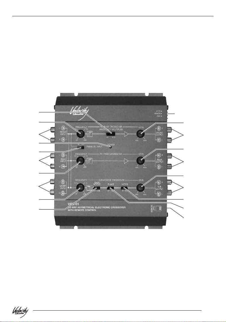
CONTROLS, INDICATORS, AND TERMINALS
1 POWER INPUT TERMINAL (RED)
To be connected to the positive terminal of your vehicle battery or other
constant +12V source.
2 REMOTE SWITCH-ON INPUT
TERMINAL (ORANGE)
To be connected to the remote control
cable or antenna lead of the source
unit for remote ON/OFF.
3 GROUND INPUT TERMINAL
(BLACK)
To be wired to the vehicle’s chassis
ground.
4 POWER INDICA T OR
This indicator lights up when the internal switching current supply is activated and the unit is operational.
5 LEFT/RIGHT FRONT CHANNEL
SIGNAL INPUTS
To be connected to the front channel
output of the source unit.
6 PARALLEL INPUT SWITCH
“IN”: When the parallel input is in the
“IN” position, the input signals coming
in through the front channel signal inputs are split and directed to the front
and rear channels simultaneously .
(This feature is to be engaged when
the source unit has no separate front,
rear or subwoofer channel outputs.)
“OUT”: If the source unit has inde-
pendent front and rear channel outputs, disengage the parallel input by
sliding the switch to the “OUT” position.
7 LEFT/RIGHT REAR CHANNEL
SIGNAL INPUTS
To be connected to the front and rear
channel output of the source unit, BUT
MAKE SURE THA T THE INPUT
SWITCH IS IN THE “OUT” POSITION.
8 LEFT/RIGHT MIXED IN/OUT
TERMINALS
As input terminal: to be connected to
the source unit.
As output terminal: to be connected to
the front channel input terminal of another electronic crossover in a multicrossover system.
9 FRONT CHANNEL HIGH-P ASS
FREQUENCY SELECTOR
For selection of front channel highpass crossover frequency between
32 Hz and 400 Hz (or 640 Hz and
8 kHz when its frequency multiplier is
in the “x20” position.)
: REAR CHANNEL HIGH-P ASS
FREQUENCY SELECTOR
For selection of front channel highpass crossover frequency between
32 Hz and 400 Hz.
; FRONT CHANNEL HIGH-PASS
FREQUENCY MULTIPLIER
Positioning this switch in the “x20” position changes the range of selectable
crossover frequencies for the front
channel high-pass from 32 Hz - 400
Hz to 640 Hz - 8 kHz.
< SUBWOOFER FREQUENCY
SELECTOR
For selection of the low-pass crossover frequency for the subwoofer channel between 32 Hz and 400 Hz.
= BASS BOOST SWITCH
When activated, this circuit provides a
single octave boost of 12 dB at 45 Hz
to compensate the woofer enclosure.
> PHASE INVERTER
Positioning the switch in the “180” Position shifts the subwoofer output signals 180 degrees out-of-phase relative to the front and rear output signals.
DEUTSCH
ENGLISH
FRANÇAIS
ITALIANO
NEDERLANDS
SVENSKA
ESPAÑOL
PORTUGUÊS
11
Page 5

CONTROLS, INDICATORS, AND TERMINALS
? SUBWOOFER STEREO/MONO
SWITCH
To select the stereo or mono mode of
the subwoofer output.
@ FRONT CHANNEL OUTPUT LEVEL
CONTROL
For adjusting the level of the front
channel output signal.
A LEFT/RIGHT FRONT CHANNEL
OUTPUT TERMINALS
To be connected to the left/right inputs
of the front channel amplifier.
B REAR CHANNEL OUTPUT LEVEL
CONTROL
For adjusting the level of the rear
channel output signal.
C LEFT/RIGHT REAR CHANNEL OUT-
PUT TERMINALS
To be connected to the left/right inputs
of the rear channel amplifier.
D SUBWOOFER OUTPUT LEVEL
CONTROL
For adjusting the level of the
subwoofer channel output signal.
E LEFT/RIGHT SUBWOOFER OUT-
PUT TERMINALS
To be connected to the left/right inputs
of the subwoofer channel amplifier.
F REMOTE LEVEL CONTROL
(OPTION)
To adjust the low-pass level from the
front of your vehicle.
Safety instructions
When carrying out installation work and making connections please observe the following
safety instructions:
- Disconnect the negative terminal of the
battery! When doing so, please observe
the vehicle manufacturer’s safety instructions.
- Make sure you do not damage vehicle
components when drilling any holes.
- The cross sections of the positive and
negative cables must not be less than
0.75 mm
- Depending on the model, your vehicle
may differ from the description provided
here. We accept no responsibility for any
damages due to incorrect installation or
connection or for any consequential
damages.
If the information provided here is not
suitable for your specific installation requirements, please contact your
Blaupunkt dealer, your vehicle manufacturer or our telephone hotline.
2
.
Features
EXCLUSIVE COMPACT CROSSOVER
DESIGN
ASYMMETRICAL ELECTRONIC
12
Page 6

SAFETY INSTRUCTIONS FEATURES
CROSSOVER DESIGN
BASS BOOST CIRCUITRY WITH QUA-
SI-PARAMETRIC EQUALIZATION
A sealed enclosure ensures a woofer’s frequency response will roll off at a rate of 12 dB
per octave below the enclosure’s resonant frequency. The quasi-parametric equalization of
our BASS BOOST circuitry provides a single
octave boost of 12 dB at 45 Hz to ensure
smooth and accurate bass response.
DC/DC REGULATED SWITCHING
POWER SUPPLY
This power supply design provides constant
voltage to the crossover regardless of the
battery’s voltage to ensure consistent output
performance at all times. This design also
eliminates switching noise due to voltage fluctuation.
FREQUENCY MULTIPLIER
The front high-pass section is equipped with
a frequency multiplier switch that can be used
to multiply the crossover frequency points.
With the additional selectable crossover
points, setting the system becomes a very
precise procedure.
PARALLEL I NPUT SWITCH
In order that a source unit has a single pair of
signal outputs, an adapter is needed to split
the front and rear inputs. With the electronic
crossover, by engaging the parallel input feature, an external adapter is no longer necessary.
FRONT/REAR INPUTS WITH
FRONT/REAR/SUBWOOFER OUTPUTS
The mobile electronic crossover has front and
rear preamp inputs and front and rear outputs, as well as a constant subwoofer output
that is independent of the front/rear fader position on the source unit.
ADJUSTABLE OUTPUT LEVEL
STEREO/MONO SUBWOOFER
GOLD PLATED RCA CONNECTORS
REMOTE LEVEL CONTROL (Option)
This remote device permits adjustment of the
low-pass level from the front of your vehicle.
Final system check
1. Pre-setting
a. Preset front, rear and subwoofer amplifier
input gain to half of their maximum.
b. Preset the crossover frequencies and out-
put levels as follows:
Bi-Amp System
Front Frequency
Selector: 160 Hz
Frequency Multiplier : x1
Rear Frequency
Selector: 160 Hz
Subwoofer
Frequency Selector: 160 Hz
Front Output Level: 10 o’clock position
Rear Output Level: 10 o’clock position
Subwoofer
Output Level: 12 o’clock position
Tri-Amp System
Front Frequency
Selector: 200 Hz
Frequency Multiplier: x20
Rear Frequency
Selector: 120 Hz
Subwoofer
Frequency Selector: 120 Hz
Front Output Level: 10 o’clock position
DEUTSCH
ENGLISH
FRANÇAIS
ITALIANO
NEDERLANDS
SVENSKA
ESPAÑOL
PORTUGUÊS
13
Page 7

FINAL SYSTEM CHECK
Rear Output Level: 10 o’clock position
Subwoofer
Output Level: 12 o’clock position
Note:
c. Preset the volume of the source unit to
its minimum (otherwise, when the source
unit is turned on, the sudden surge of
high power from the amplifiers might
cause damage to the audio components)
2. Turn the source unit on and
slowly increase the source unit
volume:
a. No Sound At All
•Turn the system off immediately .
• Check if connections have been made
properly (refer to section entitled Con-
nections for details).
• Use a Volt/Ohm meter to make sure a
good chassis ground is established for
each component that needs to be
grounded.
• Check the power input of all systems
• Check if the remote on/off terminals of all
system components are properly connected to a positive 12-volt source.
• If everything is in order, turn the power
on again. If the problem persists, refer to
the section entitled TROUBLE SHOOT-
ING GUIDE for assistance.
b. Obvious Distortion
Turn the system off and refer to the section entitled TROUBLE SHOOTING
GUIDE for assistance.
c. Out-of-Phase Problem (i.e. Abnormal
Bass)
Turn the system off and refer to the section entitled TROUBLE SHOOTING
GUIDE for assistance.
3. Noise check
Before mounting the mobile electronic crossover and the other audio components permanently, please carry out the following noise
check:
1. Start the engine and turn on the power of
the source unit.
2. Rev the engine whilst it is idling and vary
the audio volume to check for emitted engine noise or a tick-tick noise, refer to the
TROUBLE SHOOTING GUIDE for assistance. If the problem persists, consult
your local dealer directly .
3. If no unwanted noise is detected, double
check all the wiring and cables to ensure
they are secure. Then securely tighten
the mounting screws of all the audio
components.
14
Page 8

FINAL SYSTEM CHECK
TROUBLE SHOOTING GUIDE
TROUBLE SHOOTING GUIDE
SYMPTOM PROBALE CAUSE
DEUTSCH
ENGLISH
FRANÇAIS
1. No power
2. “Flickering”: The electronic crossover
power indicator switches on and off repeatedly when the audio system is on.
3. The electronic crossover heats up
quickly even when the audio system is
at moderate volume.
• Check all the ground, B+ and remote
control terminals for tight connection.
• Check all fuses.
• Use a Volt/Ohm meter to check all current carrying cables to see if the system is receiving +12V .
• Check whether the electronic crossover
B+ power input is connected directly to
the battery .
• Check the battery voltage: if low, recharge or replace it.
• Check whether the electronic crossover
has a good ground connection
(i.e.whether the ground wire is making
good contact with a bare spot of the vehicle chassis.).
• Check that all ground connections of
the entire system are making good
contact with bare metal.
• Check for speaker short: circuit disconnect speaker cable from amplifier. Test
speaker with a Volt/Ohm meter. If there
is a short circuit in the speaker wiring,
ITALIANO
NEDERLANDS
SVENSKA
ESPAÑOL
PORTUGUÊS
15
Page 9

TROUBLE SHOOTING GUIDE
SYMPTOM PROBALE CAUSE
replace the entire speaker cable or reinsulate any exposed wire with electrical tape.
4. When the engine is running, the audio
system emits a radiating noise that remains unchanged or disappears when
the volume is increased.
5. When the engine is running, the audio
system emits a radiating noise that increases or decreases with the volume of
all program sources (for radio, tape or
CD).
6. When the engine is running, the audio
system emits a whining noise that increase or decreases ONLY with the volume.
7. Obvious distortion at low volume.
• Check all the +power cables to see if
they are connected correctly .
• Check all the ground connections of
the entire system for good contact with
bare metal of the vehicle chassis.
• Check whether the source unit and the
electronic crossover are connected to
the vehicle ground at the same reference point.
• Install a 10 amp in-line filter on the red
power cable of the mobile electronic
crossover.
• If the noise persists, check the threephase current diodes and the voltage
regulator.
• This is commonly known as “radiated”
noise. It is NOT caused by the mobile
electronic crossover and thus is beyond the scope of this manual. Please
contact your local retailer/installer for
assistance.
• Output level of various channels is not
compatible, refer to section entitled
FINAL SYSTEM CHECK.
8. Overall sound effect is good, but bass is
abnormal (more bass at the two extreme
settings of the balance control than at
the center setting).
16
• The subwoofers are “out-to-phase” with
each other, thus canceling the bass
when the balance control is at the
center position. Check the wiring from
the amplifier to the subwoofers (positive “+” to positive “+” and negative “-” to
negative “-”)
Page 10

Specifications
Power source: 14.4 volts DC
negative ground
Input current: 0.5 amp. max.
Distortion: 0.01% THD at 1 V
output level
Frequency
response: 10 Hz - 30 kHz
- 3 dB
S/N ratio (A weighted): >95 dB
Separation: 60 dB
Crossover frequencies
(continuously variable)
Front high-pass:
x1: 32 - 400 Hz
x20: 640 - 8 kHz
Rear high-pass: 32 - 400 Hz
Subwoofer: 32 - 400 Hz
Crossover slope rate:
Low-pass: 18 dB per
octave 3rd
order Butterworth
High-pass: 12 dB per
octave 2nd
order Butterworth
Subwoofer boost: Single octave
0 dB to 12 dB
(variable) at 45 Hz
Input impedance: 20 kOhms
Output impedance: 100 Ohms
Output gain: 1:2 (+6 dB)
Output voltage level: 5 volts max.
Dimensions: (140 x 190 x
43 mm)
SPECIFICATIONS
DEUTSCH
ENGLISH
FRANÇAIS
ITALIANO
NEDERLANDS
SVENSKA
ESPAÑOL
PORTUGUÊS
FEATURES AND SPECIFICA TIONS
SUBJESCT TO CHANGE AND/OR IMPROVEMENT WITHOUT NOTICS
17
Page 11
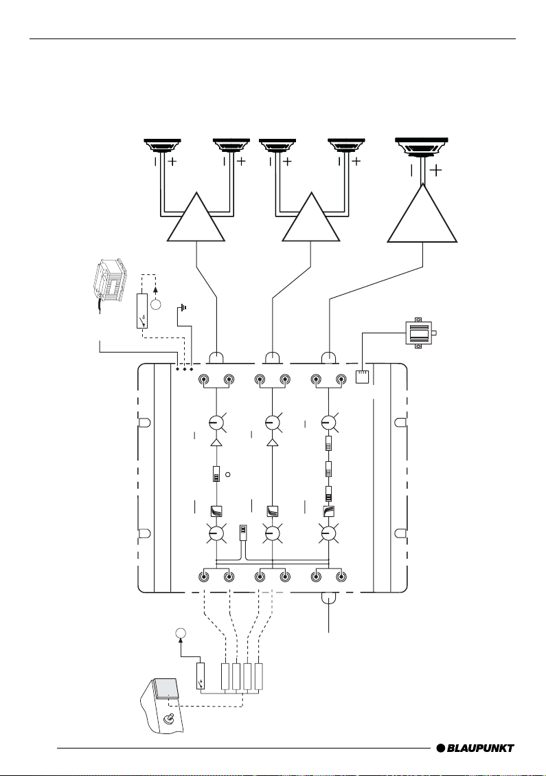
Einbau (Anschlüsse) / Installation (Connection) / Installation (Connecteurs) /
+12V
REMOTE
GND
REAR
OUTPUT
FREQUENCY MULTIPLIER
POWER
MIN
MAX
MIN
MAX
MIN
MAX
FREQUENCY
HI PASS CROSSOVER LEVEL
FREQUENCY
SUBWOOFER CROSSOVER LEVEL
FREQUENCY
HI PASS CROSSOVER LEVEL
40 70
32 400
40 70
32 400
40 70
32 400
REAR
INPUT
MIXED
INPUT
FRONT
OUTPUT
SUB
OUTPUT
MOBILE ELECTRONIC CROSSOVER
PARALLEL INPUT
IN OUT
REMOTE
LEVEL
PHASE
MODE
BASS
BOOST
0 +12dB
0° 180°
ST MO
8
12V
( FUSE )
R
L
L
R
x
FRONT
INPUT
REAR
INPUT
MIXED
INPUT
Amplifier
Amplifier
Amplifier
Front
INPUT
+12V
Subwoofer
RADIO
Remote Level Control (Woofer)
Line Out
LR
RR
LF
RF
x
+12V
FRONT
REAR
WOOFER
Installazione (Allacciamento) / Installatie (Aansluiting) / Installation
(Anslutning) / Instalación (Conexión) / Instalação (Ligação)
DEUTSCH
ENGLISH
FRANÇAIS
ITALIANO
NEDERLANDS
SVENSKA
ESPAÑOL
PORTUGUÊS
60
11
Page 12

Service-Nummern / Service numbers / Numéros du service aprèsvente / Numeri del servizio di assistenza / Servicenummers / Telefonnummer för service / Números de servicio / Número de serviço
Te l.: Fax:
Deutschland 0 18 05 00 02 25 0 51 21 49 40 02
Belgique / België 02.525. 54.44 02.525.54.48
France 014 010 70 07 014 010 73 20
Nederland 023 565 63 48 023 565 63 31
Great Britain 018 958 383 66 018 958 383 94
Ireland (01) 4149400 (01) 4598830
Danmark 44 89 83 60 44 89 86 44
Sverige 08 750 15 00 08 750 18 10
Norge 66 81 70 00 66 81 71 57
Suomi 094 359 91 094 359 92 36
Österreich 01 610 39 0 01 610 39 391
Greece 015 762 241 015 769 473
âeská republika 026 130 04 41 026 130 05 14
USA 800-266 25 28 708-681 71 88
Singapore 006 535 054 47 006 535 053 12
Slovensko 042 175 873 212 042 175 873 229
Blaupunkt GmbH
01/01 K7/VKD 8 622 402 808
 Loading...