

Page 1
KEY WEST CD169
Bosch Group
V
O
L
168 WATTS
KEY WEST CD169
PWR
MUTE
OPEN
T
U
N
/
T
R
K
SENS
SC/PS
AUD
XBASS
RPT
MIX
TS
High-Power FM/AM/CD Receiver with Detachable Face
288E8741
Robert Bosch Corporation
Sales Group —
Blaupunkt Division
2800 South 25th Avenue,
Broadview, Illinois 60153
Page 2
FCC WARNING
This equipment has been tested and found to comply with the
limits for a Class B device, pursuant to Part 15 of the FCC
Rules. These limits are designed to provide reasonable protection against harmful interference in a residential installation. This equipment generates, uses, and can radiate radio
frequency energy, and, if not installed and used in accordance with instructions, may cause harmful interference with
radio communications. However, there is no guarantee that
radio interference will not occur in particular installation. If this
equipment does cause harmful interference to radio or television reception, which can be determined by turning the equipment off and on, the user is encouraged to consult the dealer
or an experienced radio/TV technician for help.
You are cautioned that any changes or modifications not expressly approved in this manual could void your authority to
operate this equipment.
Precautions
• Avoid installing the unit where it would be subject to high
temperatures, such as in direct sunlight or a hot air stream
from the heater, or where it would be subject to dust, dirt, or
excessive vibration.
• Do not turn on the unit if the temperature inside the car is
very high. Always cool down the unit before usage. Parking
your car in direct sunlight will result in a temperature rise.
• If the unit does not turn on, check the connections first. Then
check whether the fuse at the back of the unit is blown.
• Carefully read this manual before using the unit. If you encounter any problems that are not covered in this manual,
please consult the dealer where you purchased the unit or
the dealer nearest to you.
• This unit has been designed specifically for playback of compact discs bearing the
played.
mark. Other discs cannot be
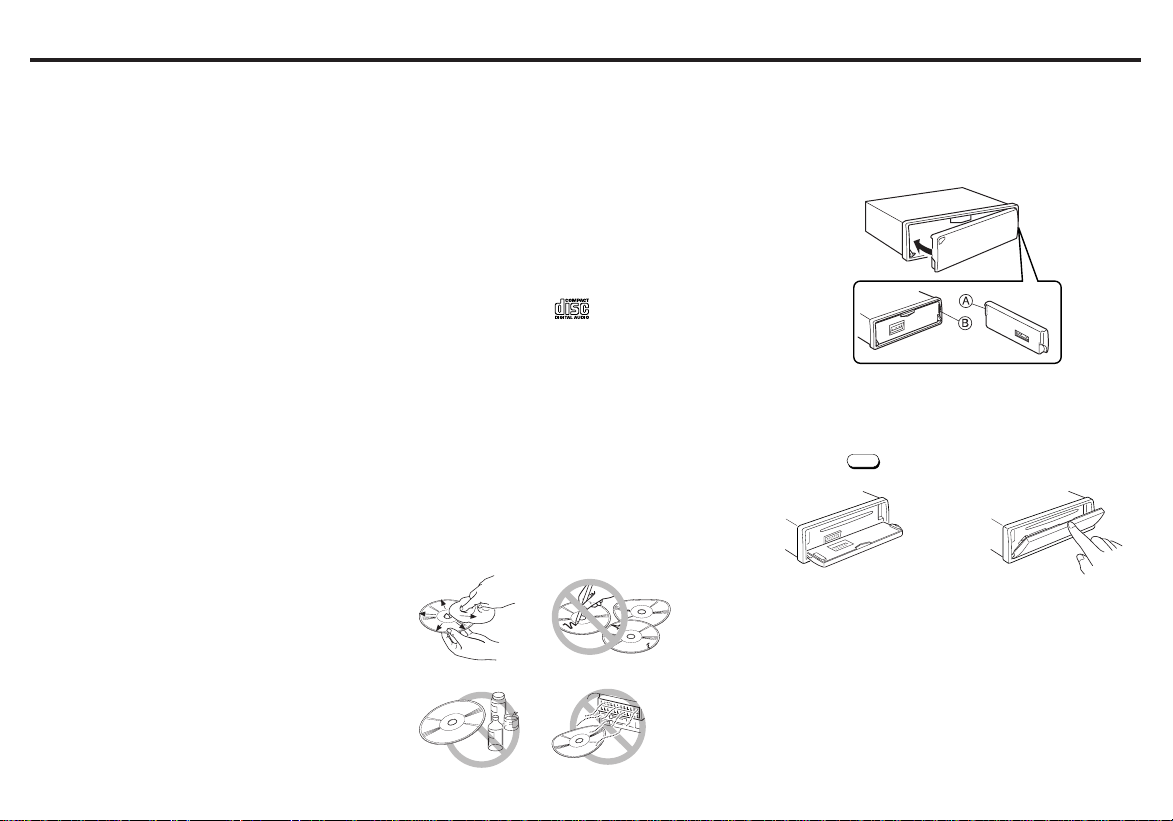
Handling the Front Panel
Attaching the Front Panel
Place the right hand side of the front panel so that the parts
A of the front panel are engaged with the parts B of the unit
as shown below. Then push the left hand side of the front
panel until it is securely locked.
Features
• Detachable Flip down front panel
• Built-in power amplifier
(max. output : 42W × 4ch)
• FM/AM PLL Synthesizer tuner
• 30 Station preset memory
• Travel Store / Scan tuning
• X-BASS System
• Station name store / Station call
Handling Compact Discs
• Be careful when removing a compact disk after the play-
back is completed because the disk may be extremely hot.
• Do not expose compact discs to direct sunlight or any heat
source.
• Check all compact discs before playing, and discard cracked,
scratched or warped discs.
• Wipe dirty or damp discs outward from the center with a
soft cloth.
• Do not use any solvents such as commercially available
cleaners, antistatic spray, or thinner to clean the compact
discs.
E-1
Front Panel Open / Close
Panel open
Press the
OPEN
.
Panel close
Raise the front panel with your
finger until it locks in place.
Page 3
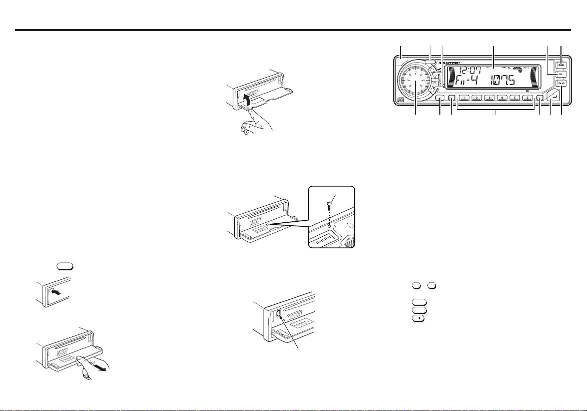
Identification of Controls
1
4/MIX
5/RPT
6/
V
O
L
168 WATTS
KEY WEST CD169
PWR
MUTE
OPEN
T
U
N
/
T
R
K
SENS
SC/PS
AUD
XBASS
RPT
MIX
TS
Notes
• Be sure to use this unit with the front panel closed.
The unit is automatically switched off when the front panel
is left open for about 10 minutes.
• Do not handle the unit roughly when opening/closing the
front panel.
• Do not put any object or use it like a tray when the front
panel is open in a lying position.
• Do not press the OPEN button when closing the front panel.
• Do not put much force to the operation buttons or the display window as it may cause damage or deform the unit.
• Connectors on the unit and front panel are vital parts transmitting the signal. Do not touch, push and scratch them.
• Be careful not to pinch your fingers or hands when opening
and closing the front panel.
• Do not press hard on the front panel when affixing it to the
unit. No more than light to moderate pressure should be
needed.
• Make sure there is no dust or dirt on the electrical terminals
on the back of the front panel as this could cause intermittent operation or other malfunctions.
Detaching the Front Panel
1.Press the
OPEN
firmly to open the flip down front panel.
2.Pull the front panel toward your direction to remove it.
3.Close the inner cover.
Do not leave inner cover in the down position unless the
front pannel is in place.
Security
Bolt the front panel with the screw (supplied) in the inner
cover as shown below, to protect the front panel from
robbery and from getting lost.
SCREW
Ejecting the CD
Press recessed button located to the left behind the Front
Panel.
EJECT button
E-2
123
13
12
11
4
10
9
1 OPEN button
2 PWR button
Turns the power of the unit on or off.
3 TUN/TRK button
Used to tune in to the desired station.
4 LCD Display window
5 CD button
Switches the CD playback mode.
6 BND/TS button
Selects the AM/FM Band & T ravel Store.
7 DISP button
Mode selector. Clock adjustment. Display priority setting.
8 MUTE/SENS button
Muting the sound. Switches the seek sensitivity between
local and distance.
9 XBASS button
Boosting the bass sound.
10 PRESET MEMORY button
During radio reception :
- 6; For Preset memory
During CD mode :
11 SC/PS button
Scan tuning. Preset scan tuning. Scan play in CD mode.
12 AUD button
Audio control selector; Bass, Treble, Loudness, Balance
& Fader.
13 Dial
Adjusts the volume level/bass/treble/balance/fader.
Storing the station names. Select Alpha-numeric characters.
; For Mix play
; For Repeat play
; For Pause
5
6
8
7
Page 4
General Operations
Volume Level Control and Memory
Rotate the dial to set the memory for the volume level which
will be recalled when the unit is turned on.
1. Adjust the volume level. Spinning or fast rotation of the
dial knob will increase the number of turns needed to
reach max. volume.
Volume down
Volume up
2. Hold the
PWR
The unit will turn off and the selected max. turn-on
volume level is set in memory.
pressed for more than 2 seconds.
Note
If the unit is turned off with the volume lower than the memory
setting, the unit will return to the lower setting when turned
back on.
Muting the sound
MUTE / SENS
Press
“ MUTE ” apeares on the display window.
T o restore the previous volume level, press
.
MUTE / SENS
again.
Setting the Clock
1. Turn the ignition key to the ON position.
2. Press the
3. Press the
A. Press the
B. Rotate the dial to set the hour digit.
C. Press the
D. Rotate the dial to set the minute digit.
PWR
DISP
(HOUR ADJ).
to turn on the unit.
to display “ CLK ADJ ”.
MUTE / SENS
within 3 seconds to flash the “ 12 ”
MUTE / SENS
to flash the “ 00 ” (MIN ADJ).
4. Press the
5. Rotate the dial to select the 12 or 24-hour time mode.
Each time you rotate the dial, the mode changes or
toggles as follows;
CLOCK 12
6. Press the
DISP
to display “ CLOCK 12 ”.
ÔÔ
Ô CLOCK 24
ÔÔ
DISP
momentarily. The clock is activated.
Ignition-off Clock Recall
The display will illuminate showing the time and then automatically shut off after 5 seconds.
Press the
tion.
DISP
while the ignition switch is in the “ OFF ” posi-
Mode Selector
Each time the
over as shown below;
Priority ➜ STN CALL ➜ LEVEL 1 ➜ Temporary ( NO NAME )
Display priority setting
Display Priority can be set for the following two items;
• Frequency and Station Name.
Example
To set Station Name to the Display Priority.
1. Press the
appears in the display window.
2. Hold the
“ NO NAME” or any station name blinks once to indicate
that Station Name is selected for the Display Priority.
After 5 seconds, the display mode will automatically return to the Display Priority showing either “NO NAME” or
the station name.
DISP
is pressed, the display window will change
➜
CLOCK 12 CLK ADJ METER 1
DISP
➜
DISP
three times, and the temporary display
pressed for more than 2 seconds.
➜
➜
Tip
Frequency Display is initially set as the Display Priority,
and Station Name (“NO NAME”) is set to “Temporary”.
Adjusting the Sound Characteristics
1. Press the
BASS 0 ➜ TREBLE 0 ➜ LOUD OFF(LOUDNESS)
R0 F0(FADER) L0 R0(BALANCE)
2. Rotate the dial to adjust the selected item.
Adjust within 3 seconds after selecting the item.
After 3 seconds, the dial functions as volume control.
Use the following tables as a guide for adjusting the settings in each mode.
BASS BASS -5 BASS +5
TREBLE TREBLE -5 TREBLE +5
LOUD LOUD OFF LOUD ON
BALANCE L9 R0(Full left) L0 R9(Full right)
FADER R9 F0(Full rear) R0 F9(Full front)
AUD
to select the desired adjustment mode.
➜
➜
➜
E-3
Page 5

Radio Reception
Seek Tuning
1. Press the
FM 1 ➜ FM 2 ➜ FT ➜ AM ➜ AT
FT & AT are Travel Store bands.
2. Press the
cally stops at a broadcasting frequency.
“ SEEK ” indicator will appear on the display window.
When tuned in to FM stereo broadcasting stations, the
“
window.
BND / TS
to select the desired band.
TUN/TRK
to tune in stations. Tuning automati-
” stereo signal indicator will appear on the display
Manual Tuning
1. Press the
2. Press the
ond to activate the manual tuning mode. Press again to
tune in to stations.
“ MANUAL ” indicator will appear on the display window.
After 4 seconds of completing Manual Tuning, the tuning
control will revert to the Seek Tuning mode.
BND / TS
to select the desired AM or FM band.
or
TUN/TRK
for more than 0.5 sec-
TUN/TRK
Scan Tuning
1. Press the
2. Hold the
The unit will scan the selected band for stations.
“ SCAN ” indicator will appear on the display window.
Press the
this on the selected frequency.
Tip
While tuning, the pie-shaped signal-strength meter
on the display is lit differently depending on the strength
of the signal. While scanning bands, the pie-shaped signal-strength meter spins. While playing CD’s, this display
spins also.
BND / TS
to select the desired band.
SC/PS
pressed for less than 2 seconds.
SC/PS
again to stop Scan Tuning and remain
Preset Scan Tuning
1. Press the
2. Hold the
“ SCAN ” indicator will appear on the display window.
The unit will scan preset memory for the 12 stations from
the AM/AT band or the 18 stations from the FM 1/FM 2/
FT bands. The unit will stop at each preset station for 8
seconds, before continuing to the next preset station.
Press the
remain this on the selected frequency.
BND / TS
to select the desired band.
SC/PS
pressed for more than 2 seconds.
SC/PS
again to stop Preset Scan Tuning and
Memorizing Stations Automatically (T ravel Store)
1. Press the
2. Hold the
Up to 6 stations with strong signals will be automatically
stored in preset memory for the selected band.
Note
This function is available for FT and AT.
BND / TS
to select the desired band.
BND / TS
pressed for longer than 2 seconds.
Memorizing Only the Desired Stations
You can store up to 6 stations on each band (18 for FM 1, FM
2 and FT, 12 for AM and AT) in the order of your choice.
1. Press the
2. Press the
3. Press and hold the desired preset memory button
flashes twice.
The number of the pressed preset memory button appears on the display window.
Note
If when you store another station on the same preset number
button, the previously stored station is replaced with new one.
BND / TS
to select the desired band.
TUN/TRK
to tune in stations.
6
for about 2 seconds until the frequency indicator
1
-
Receiving the Memorized Stations
1. Press the
2. Press the
BND / TS
to select the desired band.
1
- 6 momentarily.
Local/Distant (LO/DX) Selection
This feature is used to select the strength of the signals at
which the radio will stop during Seek Tuning.
MUTE / SENS
Press the
Local setting and only strong (local) stations will be received.
The “ lo ” indicator appears on the display window.
Pressing again will select the Distant setting and the radio
will stop at a wider range of signals, including weaker more
distant stations. The “ lo ” indicator will go out on the display
window. DX is the suggested default setting.
for more than 2 seconds to select the
E-4
Page 6

Storing the station names
You can assign a name to each radio station and store it in
memory. As many as 30 station names can be stored, composed with 8 characters each.
Storing the station names
1. Tune in a station whose name you want to store.
2. Press the
The “ NAME EDT ” will light then the “ _ _ _ _ _ _ _ _ ” on
the display window. The first “ _ ” flashes.
3. Enter the characters.
4. Press the
The station name flashes.
5. To return to the normal radio reception, Press
Erasing the station names
1. Tune in any station and press the
seconds.
2. Press the
The station name or “ _ _ _ _ _ _ _ _ ” is now flashing.
DISP
for more than 2 seconds.
A. Rotate the dial in a clockwise direction to select the
desired characters.
(A➜B➜C➜...Z➜
➜0➜1➜2➜3...9➜“ ”Space )
B. Press the
the next position. If you press
ing cursor moves to the left.
C. Repeat steps A and B to complete entering the
entire name 8 characters max.
Tip
To erase/correct a name, press the
2 seconds to clear the character and re-enter.
MUTE / SENS
MUTE / SENS
<➜>➜∗➜+➜
TUN/TRK
to move the flashing cursor to
to store the station name.
DISP
.
➜−➜′➜/
′
TUN/TRK
, the flash-
DISP
for more than
DISP
for more than 2
.
3. Rotate the dial to select the name of the station that you
want to erase. To erase all the name of the station, display “ ✳ALL DEL ”.
4. Press the
Repeat steps 3. and 4. if you want to erase other names.
5. To return to the normal radio reception, Press
DISP
for more than 2 seconds.
DISP
.
Direct Access to Memorized Stations via
Station Call
You can search for the memorized AM & FM station names in
the memory.
1. Press the
play window.
DISP
to display the “ STN CALL ” on the dis-
2. Rotate the large dial to select the desired station name.
3. Press the
MUTE / SENS
to tune in the desired station.
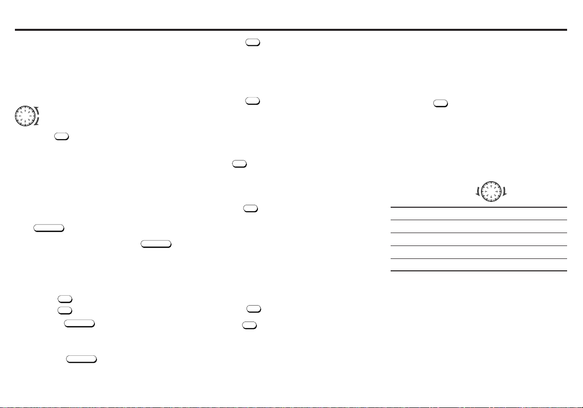
Level Meter Sensitivity selection
The sensitivity of the level meter display can be switched.
You can select :
• LEVEL 1 : Normal sensitivity
• LEVEL 2 : High sensitivity
1. Press the
2. Rotate the dial to select the desired meter sensitivity.
Level Meter selection
The meter displays can be selected from four types.
You can select :
• METER 1 : Type that the level meter goes upward.
• METER 2 : Type that only the very top segment lights.
• METER 3 : Type that the remaining segments light. (op-
• METER 4 : Type that the level meter goes up and down
• METER 0 : No meter is indicated.
1. Press the
window.
posite of METER 2)
dividing from the center segment.
DISP
to display the “ METER 1 ” on the display
2. Rotate the dial to select the desired meter indication.
METER 1 ➜ METER 2 ➜ METER 3 ➜ METER 4 ➜ METER 0
L-ch Level meter
R-ch Level meter
Enhancing the bass sound
For extended bass centered @ 72Hz, the XBASS function
can be set for either each band and CD mode.
You can select :
• XBASS 1 : Enhanced BASS level (low)
• XBASS 2 : Enhanced BASS level (Middle)
• XBASS 3 : Enhanced BASS level (High)
• XBASS 4 : Enhanced BASS level (Very high)
• XBASS 0 : No BASS enhanced/off
Press the
“
Each time you press
the display window and then the mode change as follows:
XBASS 0 ➜ XBASS 1 ➜ XBASS 2 ➜ XBASS 3 ➜ XBASS 4
E-5
DISP
window.
LEVEL 1
” appears on the display window.
to display the “ LEVEL 1 ” on the display
ÔÔ
Ô LEVEL 2
ÔÔ
XBASS
repeatedly to select the bass sound.
XBASS
, the current mode appears on
Page 7

CD Operations
6/
Playing the CD player
Loading Discs
1. Press the
OPEN
and insert the disc.
2. Close the front panel.
Playback begins automatically.
‘‘ LOADING ’’ indicator will flash in the display window.
Note
Make sure that the front panel is closed when playback
begins.
Playback with the front panel open causes the
unit to turn off automatically in about 10 minutes.
Labelled side up
! NEVER Insert a 3-inch CDs.
This unit is designed for playback of standard 5-inch CD’s
only. Do not attempt to use 3-inch CD singles in this unit,
either with or without an adaptor, as damage to the player
and/or disc may occur.
Tips
•
When a CD is loaded, the on the display remains lit.
• During playback of a CD, the pie-shaped signal-strength
meter
spins.
Listening to a disc that is already loaded
Press the CD to select the CD mode.
Playback begins automatically.
Pausing Playback
Press the
To resume playback, press the
6/
.
again.
Stopping Playback
Press the
FT or AM, AT).
BND / TS
to select the radio reception (FM 1, FM 2,
Ejecting Discs
Press the to eject the disc located behind flip-down front
panel.
Notes
• The unit will turn on automatically when a CD is inserted if
the ignition switch is ‘‘ON’’.
• When the disc is ejected from the CD slot, remove it within
10 seconds; otherwise, the disc will be reloaded automatically.
Track Search
Press the
in the display window.
TUN/TRK
during CD mode. Track numbers appear
: Playback starts from the beginning of the next track.
: Playback starts from the beginning of the current track.
Press again to play the previous track.
Cue / Review
Press and hold the
the desired point.
: To search forward.
: To search backward.
TUN/TRK
. Release when you have found
Scan Play
Press the
The ‘‘ SCAN ON ’’ indicator appears in the display window.
This will play the first 10 seconds of all the tracks on the disc.
Press the
SC/PS
during CD mode.
SC/PS
again to cancel this feature.
Repeat Play
Press the
The ‘‘ RPT ON’’ indicator appears in the display window and
the current track is played repeatedly.
Press the
5/RPT
during CD mode.
5/RPT
again to cancel this feature.
Mix Play
Press the
All the tracks on the current disc are played in random order.
Press the
4/MIX
during CD mode.
4/MIX
again to cancel this feature.
E-6
Page 8

Installations
Supplied Mounting Hardware
Sleeve
Bushing Mounting Strap Release
& Screws and Screw Keys
Precautions
• Be sure to detach the front panel before you start installing the unit.
• When mounting the unit in a car, keep the unit as level as
possible. If the unit must be mounted at an angle, due to the
design of the vehicle, make sure that the unit does not lit by
more than 30˚.
• Choose the mounting location carefully so that the unit will
not interfere with the normal driving operations of the driver.
• Use only the supplied mounting hardware for a safe and
secure installation.
Mounting Example
Installation in the dashboard.
1. Install the sleeve in the dashboard.
2. Select and bend the appropriate tabs to hold the sleeve
firmly in place.
Mounting Strap Use
3. Attaching the Mounting Strap to the underside of the dash
board, using screw.
Attach the back of the unit to the Mounting Strap using
the support stem bolt and hardware.
Bushing Use
3. As shown in the figure below, securely fasten the screw,
which has been inserted into the bushing, to the rear of
the set.
Fire wall
The distance to the fire wall is
various due to the type of the car.
Be sure to secure the unit by
properly inserting the bushing.
Caution
Insufficient fastening of the
screw may cause some CD’s to
skip.
E-7
If your car has no accessory position on the
ignition key switch (POWER SELECT switch)
The illumination on the front panel is factory-set to be turned
on even when the unit is not being played. However, this setting may cause some car battery wear if your car has no accessory position on the ignition key switch. To avoid this battery wear, set the POWER SELECT switch located on the
bottom of the unit to the
button. The illumination is reset to stay off while the unit is not
being played.
Reset button
Press the reset button with the point of
a sharp object such as a ball-point pen.
POWER SELECT SWITCH
(Located on the bottom of the unit)
Change the position with a jeweler’s screwdriver, etc.
A : Your car has an accessory position on the ignition
switch.
B : Your car has no accessory position on the ignition
switch.
Be sure to
and connecting the lines.
press the reset button after changing the switch
B position, then press the reset
Page 9

Connections
ADDITIONAL
SPEAKERS
EXTERNAL
AMPLIFIER
REMOTE
(IF ANY)
LEFT FRONT
SPEAKER
WHITE W/BLACK STRIPE
LEFT REAR
SPEAKER
WHITE
GREEN
GREEN W/BLACK STRIPE
BLUE
ANTENNA
REMOTE
(IF ANY)
RED
YELLOW
BLACK
DETACHABLE
WIRE HARNESS
PRE-AMP
OUTPUTS
REAR OF UNIT
ANTENNA
SOCKET
BATTERY
(CONSTANT
POWER)
IGNITION SWITCH
GRAY
GROUND
RIGHT FRONT
SPEAKER
GRAY W/BLACK STRIPE
VIOLET W/BLACK STRIPE
VIOLET
RIGHT REAR
SPEAKER
FUSE (10A)
Caution
• Connect each pair of speaker leads only to a single speaker
(or speaker system) that has an impedance of least 4 ohms,
as well as 42 watts power-handling capability.
• Do not connect speaker leads to any inputs on external
amplifiers. This will cause damage to the internal amplifier
of this unit.
Connection procedure
Warning
• To prevent short circuit, remove the key from the ignition
and disconnect the battery’s (–) (minus) terminal.
• This unit is designed for negative ground 12 V DC operation
only. You can not use it for 24 V or other types of car batteries.
1 Make sure the car’s ignition key has been removed.
2 Disconnect the minus terminal of the car’s battery.
3 Connect the wiring harness wires in the following
4 Connect the speaker wires of the wiring harness.
5 Connect the car’s antenna terminal to the antenna
order : GND (Black), BTT (Yellow), ACC (Red) and
ANTENNA REMOTE (Blue), and tape each so they do
not come in contact with each other.
socket of the unit.
6 Connect the detachable wire harness to the unit.
7 Reconnect the minus terminal of the car’s battery.
8 Start the car’s engine.
9 Make sure the unit operates properly.
Connection Example
E-8
Page 10

Maintenance
Replacing the Fuse
If the fuse is blown, check the power connection first and then
replace the fuse. If the fuse blows again under normal conditions, the unit may be defective.
Back of the unit
Warning
Use only a fuse with the specified amperage (10 A).
Use of another type of fuse can result in a fire or unit damage.
Cleaning the Connectors
If the connectors of the unit and the front panel are contaminated, malfunctions may occur.
Detach the front panel and clean the connectors with an alcohol dampened cotton swab as shown below.
Main unit Back of the front panel
Returning to the Initial Settings
When the reset button is pressed, the microcomputer of the
unit returns to the initial settings. If the display window is not
properly shown or the unit malfunctions, press the reset button with the point of a sharp object such as a ball-point pen.
Removing the Unit
Use the supplied release keys when you need to remove the
unit from the car.
Insert the “ TOP R ’’and “ TOP L ’’of the release keys on the
right and left position until it clicks respectively, to remove the
unit.
As shown in the figure below, push the plate spring firmly to
remove the release keys.
Notes
• Handle the release keys carefully to avoid injuring your fingers.
• Keep the release keys in a safe place for future use.
Reset button
E-9
Page 11

Troubleshooting Guide
Specifications
The following check will assist in the correction of most problems which you may encounter with your unit. Before going
through the check list below, refer back to the connection and
operating procedures.
General
Trouble
No sound
Indications do not appear
on the display window.
Cause/Solution
Adjust the volume with the dial.
Set the fader control to the center position with a 2-speaker system.
Remove the front panel and
clean the connectors with cotton
swab dipped in isoprophyl alcohol (90% or higher).
Radio reception
Trouble
Preset stations are not re-
ceivable.
Automatic tuning is not pos-
sible
Travelstore feature does not
complete storing of six stations.
Also make sure that antenna is connected, extended and dry
inside.
If the above mentioned solutions do not help to improve the
situation, consult your nearest Blaupunkt dealer or in the
United States call 1-800-266-2528 for technical assistance,
parts and service. Call 1-800-950-2528 for dealer referral or
to request product brochure.
Cause/Solution
The broadcast is too weak.
The broadcast is too weak.
→ Use manual tuning.
Not enough broadcast frequencies are receivable.
CD Player Troubleshooting
When problems occur with CD playback, an error message
appears in the display window.
Refer to the table below to identify the problem, then take the
suggested corrective action. If the “ MECA ERR ” appears or
“ SW ERROR ” persists, contact your nearest Blaupunkt
dealer.
Message Possible cause Recommended action
CD ERROR Dirty disc. Clean the disc.
SW ERROR Mechanical problem. Eject and reinsert.
Scratched disc. Replace the disc.
Up-side-down. Check the disc.
Focus error. Try ejecting and
Data and focus error. Under normal tempera-
reinserting under normal
temperature conditions.
ture conditions, eject
and insert clean, undamaged disc properly.
GENERAL
Dimensions : Approx. 178 mm × 50 mm × 155 mm
Power requirements : 12 volts DC car battery
Output Power : 42 watts × 4 channels
Output Wiring : Floating-ground type designed for 4
Output Impedance : Compatible with 4-8 ohm speakers.
Low - Level Output : 2 V.
(W × H × D)
(negative ground)
speaker use.
RCA low-level outputs (2 channels).
TUNER
Tuning Range : AM : 530 - 1,710 kHz (10 kHz step)
Sensitivity : AM : 20 µV
FM
Stereo Separation : 30 dB
FM : 87.5 - 107.9 MHz (200 kHz step)
FM : 1.5 µV
CD PLAYER
Frequency
Response : 20 - 20,000 Hz
S/N Ratio : 90 dB
Wow & Flutter : Below the measurable limit
E-10
 Loading...