

Page 1
Page 2

FCC W arning
The equipment has been tested and found to comply with the limits for a Class B device, pursuant
to Part 15 of the FCC Rules. These limits are designed to provide reasonable protection against
harmful interference in a residential installation. This equipment generates, uses, and can radiate
radio frequency energy, and, if not installed and used in accordance with instructions, may cause
harmful interference with radio communications. However, there is no guarantee that radio
interference will not occur in particular installation. If this equipment does cause harmful
interference to radio or television reception, which can be determined by turning the equipment off
and on, the user is encouraged to contact the dealer or an experienced Radio/TV technician for
help.
You are cautioned that any changes or modifications not expressly approved in this manual could
void your authority to operate this equipment.
CAUTION
• The use of optical instruments with this product will increase eye hazard.
• Because the invisible laser beam in this compact disc player is harmful to the eyes, do not
attempt to disassemble this cabinet. Refer servicing to qualified personnel only.
SAFETY CERTIFICATION
This Compact Disc Player is made and tested to meet exacting safety standards. It meets FCC
requirements and complies with safety performance standards of the US Department of Health and
Human Services.
Owner’s Record
The model and warranty numbers are located on the top of the unit. Record the warranty (serial)
number in the space provided below. Refer to these numbers whenever you call upon your
Blaupunkt dealer regarding this product.
Warranty Number _____________
Attach Sales Receipt Here
2
Page 3

Table of Contents
English
FCC Warning .................................................... 2
Owner’s Record................................................ 2
Features............................................................ 4
Precautions....................................................... 4
Detachable Face .............................................. 5
Electrical Connections and Installation ............ 6
Installation ........................................................ 8
Maintenance ................................................... 10
Specifications ................................................. 11
Location of Controls ....................................... 12
Instructions—General Operation ................... 13
Audio Operation.............................................. 1 4
Radio Operation ............................................. 14
CD Player Operation ...................................... 15
Auxiliary Input Jack ........................................ 1 7
Direct Software Control Menu ........................ 19
Wireless Remote Control .............................. 22
Troubleshooting Guide ................................... 23
Français
Avertissement de la FCC ............................... 24
Archive du Propriétaire................................... 24
Caractéristiques.............................................. 25
Précautions à Prendre.................................... 25
Face Avant Amovible ..................................... 26
Raccordements Électriques et Installation .... 27
Installation ...................................................... 29
Entretien ......................................................... 31
Spécifications ................................................. 32
Emplacements des Commandes ................... 33
Mode d’Emploi/Fonctionnement Général ...... 3 4
Fonctionnement de la Audio .......................... 3 5
Fonctionnement de la Radio .......................... 35
Fonctionnement du Lecteur de CD ................ 37
Prise Auxiliare................................................. 3 8
Menu ............................................................... 42
Guide de Dépannage ..................................... 46
Español
Advertencias FCC ........................................47
Registro del Propietario................................47
Características..............................................48
Precauciones ................................................48
Panel Frontal Desmontable (Carátula) ........49
Conexiones Eléctricas e Instalación ............50
Instalación ....................................................52
Mantenimiento ..............................................54
Especificaciones...........................................55
Ubicación de los Controles ..........................56
Instrucciones de Funcionamiento ................57
Funcionamiento de Audio ............................ 58
Funcionamiento de la Radio ........................59
Funcionamiento del CD................................60
Tomada de Entrada Auxiliar.........................61
Menu .............................................................65
Guía para la Solución de Problemas ...........69
Portuguese
Aviso da FCC ...............................................70
Registro do Proprietário ...............................70
Características..............................................71
Precauções...................................................71
Painel Removível..........................................72
Conexões Eléctricas e Instalação................73
Instalação .....................................................75
Manutenção ..................................................77
Especificações..............................................78
Posição dos Controles .................................79
Instruções-Funcionamento Geral.................80
Funcionamento do Audio .............................81
Funcionamento do Rádio ............................. 82
Funcionamento do CD .................................83
Tomada para Entrada ..................................85
Menu .............................................................88
Guia para Solução de Problemas ................92
3
Page 4

ENGLISH
Features
Congratulations on your purchase of this Blaupunkt CD Receiver. Its Codem III-US FM/AM Tuner,
3-Beam Laser/Anti-Vibration & Shock mechanism provide the ultimate in sound reproduction. Its
high-power amplifier and 4-Channel RCA preamp output provide you with tremendous system
configuration flexibility. It’s auxiliary input jack lets you easily incorporate portable audio equipment,
such as a cassette or DAT player, into your car’s sound system. Blaupunkt’s exclusive Direct
Software Control Menu allows you to customize many of the units features to your specific
preferences.
• Codem III-US Tuner Features:
–Multipath Management
–ASU Electrical Impulse Noise Reduction
– Superior AM Frequency Response
–18 FM/6 AM Presets, Including 6 FM &
6 AM Travelstore Presets
–Station & Preset Scans
–Station Naming
– Tuner Timer
–Local/Distant Seek & Manual Tuning
• CD Player Features
–Track Up/Down
– Scan, Mix, Repeat
–Cue/Review & Pause/Play
–CD IN Indicator
–Last Position Memory
– 3-Beam Laser Pick-Up
– 1 Bit/8 Times Oversampling Digital Filter
– Silicone-Oil Dampened Anti-Vibration and
Shock CD Mechanism
Your unit’s fully-detachable front faceplate
makes the unit useless to would-be thieves.
• Audio Features:
–35 Watts x 4 Channel Integrated Amplifier
–Dual-Level Fader
–Over 3 Volts of Distortion-Free Preamp Output
4-Channel, Low Impendance (200 Ω Preamplifier)
–2-Channel RCA Preamp Output Harness Included
–Bass,Treble, Balance, Fader Controls
–Source Tone & Loudness-Level Memory
–Adjustable Maximum Turn-On Volume & Mute
–Auxiliary Input
• Other Features:
–16 Direct Software Control Menu Options
–Detachable Face with Hardshell Case
–Green Illumination
–Source Display Priority
–Clock/Ignition-Off Clock Recall
–180 x 50 x 155 mm (7 x 2 x 61/8 in.) DIN/ISO Chassis
–Detachable Wire Harness w/Bullet Connectors
–Snap-In DIN Sleeve & Mounting Hardware
– Side Bracket Compatible
–Optional RC-06H Wireless Remote Control included
Optional Thummer™ Steering Wheel Mounted
Wireless Remote Control
Designed, Engineered and Manufactured By Blaupunkt.
Traffic Safety and Precautions
• Do not adjust your unit in difficult driving conditions that demand your full attention.
• As the driver of a motor vehicle, it is your responsibility to pay attention to the traffic situation at all
times. Never use your unit in a way that could distract you.
• Always make sure that you are still able to hear any warning signals coming from outside of the
vehicle, such as police or fire engine sirens, so that you can react accordingly.
• If your vehicle was parked in direct sunlight resulting in a considerable rise in temperature inside
the vehicle, allow the unit to cool off before operating your unit.
• The use of optical instruments with this product will increase eye hazard.
• Because the invisible laser beam in this compact disc player is harmful to the eyes, do not
attempt to disassemble this cabinet. Refer servicing to qualified personnel only.
• You are cautioned that any changes or modifications not expressly approved in this manual could
void your warranty.
• Car Wash precaution - If you have a motorized antenna, make sure to turn off the unit – not just
the tuner – so that the antenna is lowered and antenna damage is prevented!
4
Page 5
Detachable Face
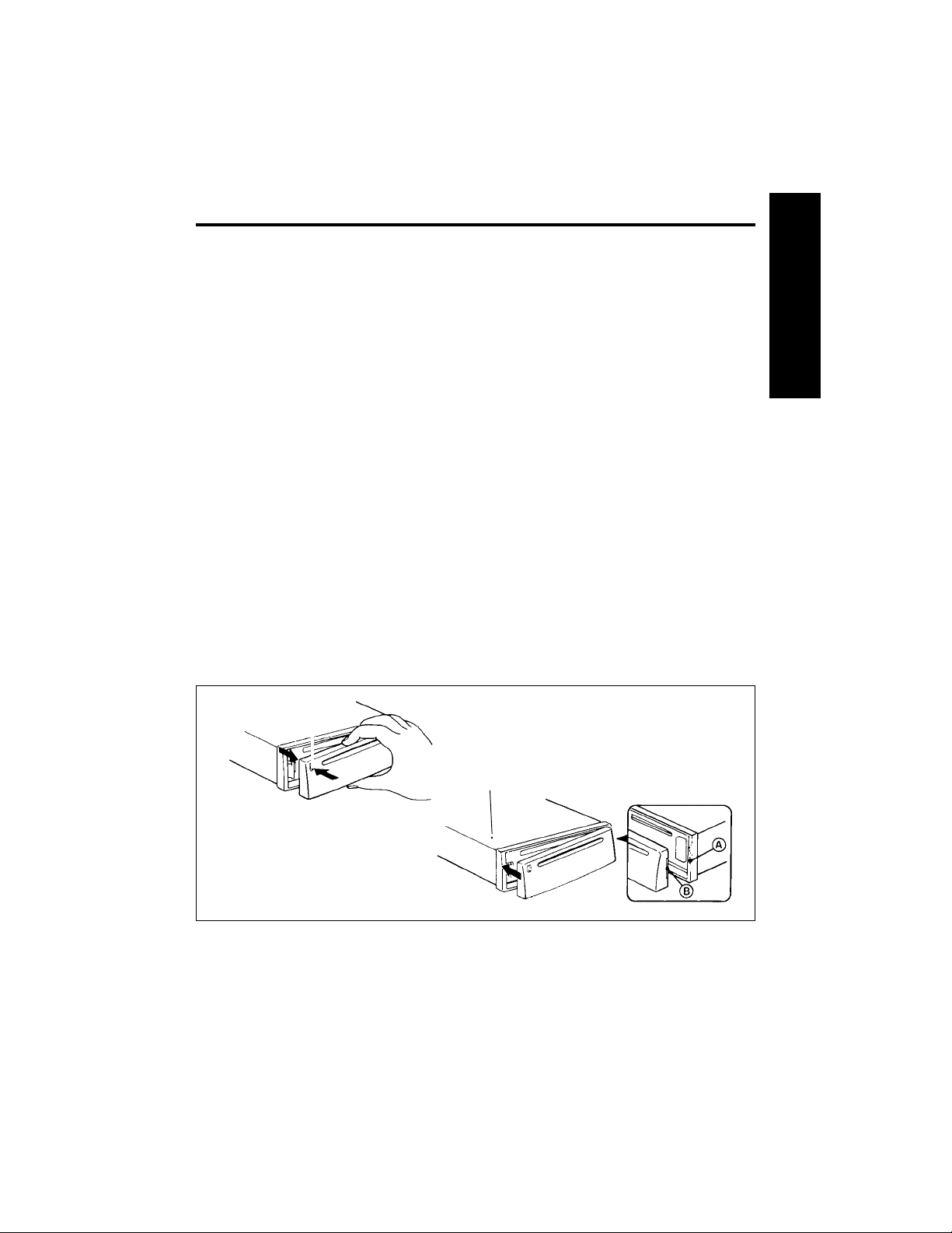
Detaching & Attaching the Face:
The face of this unit can be detached and taken with you to prevent it from being stolen.
Detaching the Face:
Before detaching the face, be sure to press the PWR Button first. Then press the REL (Release)
Button and detach the face by gently pulling it off as illustrated.
Note: Do not pull it straight out from the chassis. Be sure not to drop the face when detaching it
from the chassis.
Attaching the Face:
Apply the right hand side of the face to the chassis by sliding (part B) of the face to (part A) at the
front of the chassis. Gently push the left side of the face against the front of the chassis until it
snaps into place.
Note: Make sure that the face is inserted right side up. Do not press against the display window.
Do not press hard against the face when attaching it to the chassis, it may be easily attached with
gentle pressure. When carrying the face with you, put it in the carrying case. Do not expose the
face to direct sunlight, heat sources such as hot air ducts or leave it in a humid place. Never leave
it on the dash board of a vehicle parked in direct sunlight, where there may be a considerable rise
in temperature inside the vehicle.
Affixing Faceplate For Retail Display:
The faceplate can be affixed to the unit’s chassis, which is desirable for a retail display, for
example.
To affix the faceplate:
Insert the black bolt into the hole at the left front of the top of the radio. See* below.
E
N
G
L
I
S
H
*
5
Page 6

Electrical Connections and Installation
@/<?#&*>@! To avoid the aggravation of costly mistakes and serious damage that could make
you feel this way, please carefully read all of the instructions before you begin. Carefully follow all
instructions. You’ll be glad you did!
GENERAL RECOMMENDATIONS
• If you’re not confident that you can install the unit correctly, have it installed by a qualified
Blaupunkt installation technician.
• Use this unit only with negative ground 12 Volt (11-16 Volt) direct current (DC).
• Be sure to detach the faceplate before you start to connect or install the unit.
• Don’t assume that a seemingly matching wire harness in the vehicle has leads that match the
leads of the unit’s wire harness.
• We recommend making and testing all electrical connections before installing the unit. Connect
the leads (wires) according to instructions and diagram below.
ELECTRICAL CONNECTION INSTRUCTIONS
1. Disconnect the vehicle battery’s negative terminal before making connections.
2. Connect the speakers and/or external amplifiers (if you have any) following the guidelines in
the SPEAKER CONNECTION section below.
3. Connect the blue (trigger output) lead to an antenna motor trigger switch input terminal (if you
have one). (Maximum amperage required must not exceed 150mA.)
4. If you have an external amplifier, connect the blue/white lead to the amplifier’s trigger switch
terminal. DO NOT connect the blue/white lead to the antenna’s power supply input. (Maximum
amperage required must not exceed 150mA.)
5. If you have a cellular telephone set that has a mute lead (lead that supplies constant ground
when telephone is in use), connect it to the dark green lead.
6. Connect the black (power ground) lead to a grounded metal part on the vehicle. We
recommend grounding all audio system black ground leads (receiver, external amplifier, etc.) to
a common grounding point, preferably a non-painted surface under the instrument panel.
7. Connect the yellow (constant power) input lead to a source of constant battery power,
preferably a terminal to an appropriate slot in the fuse box.
8. Connect the red (turn-on power) input lead only after the other leads are connected. Be sure to
connect the red lead to a positive (+) 12 Volt power terminal that is energized only when the
ignition key is set to the on position or accessory position.
9. Cover the ends of any unused leads with electrical tape. This will prevent them from touching
the vehicle or each other and causing a short-circuit and damage to the unit or vehicle.
10. Reconnect the vehicle’s battery.
11. Verify that no fuses have blown.
12. Plug the harness into the unit.
13. Attach the faceplate and test the unit.
Once the connections have been successfully made, you can begin to mount the unit.
SPEAKER CONNECTIONS
The unit’s Dual-Level Fader allows you to fade between the front and the rear channels using
either the front and/or rear speaker leads and/or the rear preamp outputs, providing you
tremendous flexibility in configuring your speaker arrangement:
• You can connect a speaker (regular, co-axial or tri-axial speakers or component speaker system,
all hereafter referred to simply as “speaker”) to each of the units’ four pairs of speaker leads.
• You can connect the 2 RCA preamp outputs to multiple external amplifiers and power multiple
speakers or speaker systems through the amplifiers. (Blaupunkt amplifiers and speakers
available separately). To add front preamp output, purchase Blaupunkt part 8634494218.
• You can use a either or both of these two methods.
Connecting the Speaker Leads
To prevent short circuits or serious damage to the unit and/or speakers:
• Connect the speaker leads only as indicated in the wiring diagram. Disconnect the vehicle
6
Page 7

battery’s negative terminal before making connections.
• Only use speakers that have impedance ratings of 4 ohms or higher and have power-handling
capabilities greater than the receiver’s stated power level.
• The unit’s internal amplifier is designed to handle a 4-ohm load on each pair of speaker leads.
• DON’T connect two speakers to a single pair of speaker leads (“in parallel”) unless both speakers
each have at least 8 ohms impedance.
• DON’T connect the left and right speaker leads to each other or to the same speakers.
• DON’T connect the front and rear speaker leads to each other or to the same speakers.
• DON’T connect the negative speaker leads to each other.
• DON’T connect the positive speaker leads to each other.
• DON’T connect any active speakers (with built-in amplifiers) to the speaker leads unless their
owner’s manuals specifically state that this is O.K.
• Cover the ends of any unused leads with electrical tape. This will prevent them from touching the
vehicle or each other and causing a short-circuit and damage to the receiver or vehicle.
Connecting the Pre-Amp Outputs to External Amplifier(s)
To prevent short circuits or serious damage to the receiver, amplifier, and/or speakers:
• Follow the amplifier’s instructions on how to connect the unit’s preamp outputs to the amplifier(s)
and connect the speaker(s) directly to the amplifier.
ANTENNA MOTOR
TRIGGER SWITCH
SWITCH
7
Page 8

Installation
Recommendations
• Carefully choose the mounting location so that the unit won’t interfere with normal driving.
• Avoid mounting locations where the unit would be subject to high temperatures, such as from direct
sunlight or hot air from the heater, or where it would subject to dust, dirt or excessive vibration.
• The illustration below shows a typical installation, however, you may need to adjust the
installation, depending on the unit. If you have questions or need additional installation hardware,
consult your Blaupunkt dealer.
• Make sure the unit is firmly anchored (preferably at both front and back) and does not vibrate.
Mounting Hardware
(1)
Sleeve
(2)
Mounting Strap
and Screw
(3)
Release Keys
Mounting The Unit in Most Dashboards
1 Install the Sleeve (1) in the dashboard.
2 Select and bend the appropriate tabs to hold the sleeve firmly in place.
3 A. Attach the Mounting Strap (2) to the underside of the dashboard, using screw.
B. Attach the back of the unit to the mounting strap using the support stem bolt and hardware.
Bend these tabs
Dashboard
8
Page 9

Mounting the Unit in a Japanese Car
You may have difficulty mounting this unit in some Japanese cars that have ISO mounting features
(side-bracket mounting systems). In this case, consult your Blaupunkt dealer.
1 Run a blade along the slits on the back of the front trim ring and separate it from the unit.
Save the trim rin in case you ever in case you ever want to instal the unit in another vehicle.
2 Use the vehicle’s own mounting hardware to attach the unit.
1
2 NISSAN
2 TOYOTA
max. size M5x8
Slit
to dashboard/center console
max. size
M5x8
Bracket
Support
max. size M5x8
to dashboard/center console
max. size
M5x8
Bracket
Support
9
Page 10

Maintenance
Removing the Unit
Use the Release Keys as shown below. Keep them in a safe place in case you need them in the
future.
Fuse Replacement
When replacing the fuse, be sure to use one with the correct amperage, which will be stated on the
fuse case. Never use a fuse that has a stated amperage exceeding the one supplied for this unit, as
this could cause malfunction and serious damage to the unit.
Cleaning the Connectors
The unit may not operate properly if the connectors between the unit and the face are contaminated
with dirt. In order to prevent this from happening, remove the face from the unit by pressing the REL
(Release Button), then detach it and clean the connectors from time to time. Clean the connectors
with a cotton swab and isoprophyl alcohol (90% or higher). Be sure to clean them with a vertical
motion. Never clean them horizontally, because this could damage the contact points.
10
Page 11

Specifications
Audio Power Specifications
Power Output and Total Harmonic Distortion: 13.5 watts per channel minimum continuous average
output into 4 ohms, 4 channels driven, from 30-15,000 Hz with no more than 1% total harmonic
distortion.
Other Specifications
Tuner
FM
Tuning Range: 87.5 - 107.9 MHz
Intermediate Frequency: 10.7 MHz
FM Mono Sensitivity: 13 dBf
Seek lo sensitivity: 51 dBf
Seek sensitivity 31 dBf
Selectivity: 80 dB at 400kHz
Signal-to-Noise Ratio: 65 dB (stereo), 70 dB (mono)
Harmonic distortion at 1 kHz: 0.7% (stereo), 0.5% (mono)
Separation: 30 dB
Frequency Response: 30-15,000 Hz ± 3 dB
AM
Tuning Range: 530 - 1,710 kHz
Seek lo sensitivity 50 dBµV
Seek sensitivity: 25 dBµV
Intermediate Frequency: 450 kHz
Signal-to-Noise Ratio: 50 dB
Frequency Response: 30-5,000 Hz
CD Player
Signal-to-Noise Ratio: 90 dB
Dynamic Range: 90 dB
Frequency Response: 5-20,000 Hz + 3 dB
Harmonic Distortion: .01%
Audio
Speaker Impedance: 4-8 ohms
Maximum Amp Power: 4 X 35 Watts (at 4 ohms)
RMS Power: 4 X 13.5 Watts (at 4 ohms) <1% THD
Bass Control: ± 10 dB @ 100 Hz
Treble Control: ± 10 dB @ 10 kHz
Loud1: + 8 dB @ 60 Hz & + 2 dB @ 8 kHz
Loud2: + 12 dB @ 60Hz & + 4 dB @ 8 khz
Preamp Outputs: 4-Channel, Low-Impendance (200 Ω) Preamplifier
Preamp Output Voltage: Over 3 Volts of Distorsion-Free Preamp Output
General
Dimensions (w/o projecting parts/controls): 180 x 50 x 155 mm
Mass: Approx. 1.4 kg (3.0 lb.)
Power Requirement (neg. grnd.): 12 V DC car battery (11-16 V DC allowable)
Operating Temperature: 15°F to 120°F, –10°C to 50°C
Supplied Accessories: • Unit
Optional Accessories: • 4-Channel Preamp Output Harness (Part No. 8634494218)
7 x 2 x 6
• Faceplate
• Wire Harness, including 2-Channel RCA Preamp Output
Harness
• DIN Sleeve
• Mounting Hardware
• Owner’s Manual in English, French, Spanish and Portuguese
• RC-06H Wireless Remote Control
• Thummer™ Steering Wheel Mounted Wireless Remote
Control
Design and specifications subject to change without notice.
1
+ 3dB
/8 in.
11
Page 12

Location of Controls
1
5
6
1. REL (Release) Button
2. Disc Insertion Slot
3. Eject
4. SRC (Source) Change
5. PWR (Power) Button
6. Volume +
7. Volume –
8. Mute/Audio Button
Mute, Bass, Treble, Balance/Fade Access
Name Storing/Deletion/Exit
Minute: 00
9. DIS (Display)/MENU Button
Display Change
Menu Access
Demo Message Off/On (8 second press)
10. /\
Seek Tuning Up
Menu Feature Select
Bass, Treble Increase
Fade to Front
Name Character Select
11. V Button
Seek Tuning Down
Menu Feature Select
Bass, Treble Decrease
Fade to Rear
Name Character Select
12. <<
Manual Tuning Down
Menu Feature Adjust
Track Down
Audible Review
11
987
10
12
13
23
14
Bass, Treble Decrease
Balance Left
Name Character Position
13. >>
Manual Tuning Up
Menu Feature Adjust
Track Up
Audible Cue
Bass, Treble Increase
Balance to Right
Name Character Position
14. Display
15. RPT (Repeat) Track Repeat
16. BND (Radio Band)/Travel Store Button
FM/AM Band Acces
FM/AM Travel Store
17. MIX Button
18. SCA (Scan) Button
Station Scan
Preset Scan
Track Scan
19. Pause Button
20. LD (Loud)/SENS Button
Loudness On/Off
Tuning Sensitivity Select
21. FM/AM Preset Buttons
16
1715
4
2118
2019
12
Page 13

Instructions — General Operation
See Traffic Safety & Precautions on page 4.
“Press”
means a momentary press of less than 1/2 second. All presses requiring more than 1/2
second are followed by beep. (Beep for all button presses available through Direct Software
Control Menu.)
“Time Out”
automatically exit the procedure after 4 seconds of inactivity. (8 for Menu mode.)
Ignition-Off Clock Recall
Any button press while ignition off displays time for 8 seconds.
Ignition-On
Unit lights up and clock is displayed.
Demo Mode
The unit is programmed to scroll some key features across the display if no button is
pressed for one minute . (You may have seen this at the store where you purchased your
radio.) TO TURN THIS OFF, turn the unit on and press DIS for 8 seconds until “DEMO OFF”
appears. (Pressing DIS for 8 seconds again will re-activate this feature.)
Release for Detachable Faceplate
Push REL to detach face. Already-inserted CD remains in unit. Current settings and source mode
are stored, except when detach occurs during Menu mode, new Menu settings are not stored. If
power was not switched off before face removed, unit will automatically power-on when face is
reattached.
Power (PWR) On/Off
When ignition on, press PWR or insert a disc to turn unit on. Last-used source becomes active,
unless unit is turned on by inserting disc, in which case CD player becomes active. Display
sequence at Power-On:
Display Options
Press DIS to change information shown at times when no manual or automatic activity takes place.
Choice of priority display is separate for each audio source:
When additional button presses are anticipated to complete a procedure, the unit will
1.Turn-On Message (To turn message off or modify message, see Menu, page 19.)
2.“RADIO”, “CD PLAY” or “AUX IN”.
3.Functional information sequence (See Display Options, below.)
4.Priority display for active source.
Radio: Station Name (if named) —> Frequency —> Clock
CD: Track No./Elapsed Play Time —> Clock
AUX: “AUX IN” - Clock
After a change in source, radio station or CD play, the current source’s non-clock displays are
shown in sequence, then display returns to current source’s priority display.
Source (SRC)
Use SRC to select source - radio or CD (if already inserted) and/or auxiliary input (even if no input
on aux in line) as per model’s features.
Power Off
Press PWR for more than 1/2 second to turn unit off. Unit stores current settings for source,
station or track, etc. Antenna and amplifier trigger wires shut off voltage. (If faceplate still attached,
display switches to clock.)
13
Page 14

Audio Operation
Volume Control Buttons (+/–)
Press + and - to increase/decrease volume from 0 to 63, in increments of 1.25 dB/step. Volume
control is accessible from all modes except Name Access and Edit modes.
Mute & Cellular Mute
Press Mute to temporarily reduce volume to level set under Menu. “MUTE” appears. (Same mute
level is also activated by cellular mute (if connected). “TEL MUTE” appears.) Mute or cellular mute
is terminated by pressing any button. (Cellular mute is also ended by ending cellular telephone
use.) If volume level lower than mute level, lower volume level is maintained, even though “MUTE”
appears.
Automatic Source Tone Memory
Bass and treble adjustments made are source specific, allowing different settings for each source
(FM, AM, CD, Auxiliary) as is Loudness.
Bass, Treble, Balance and Fade
Press Mute/AUDIO for more than 1/2 second to access Bass. Subsequent presses access Treble
mode, then Balance/Fader mode.
Bass -Adjust from +7 to -7 at 2 dB/step using >> or /\ to increase bass, << or V to decrease.
Treble - Adjust from +7 to -7 at 2 dB/step using >> or /\ to increase treble, << or V to decrease.
Balance/Fade (“BAL/FADE”) Adjust balance from L9 (all the way left) using << to R9 (all the way
right) using >>. Adjust fader from F9 (sound only from the front) using /\ to R9 (sound only from the
rear) using V.
Loudness (LD)
Press LD to increase sound of low and high frequencies. Loudness level set under Menu and
is source dependent. LD icon appears. To cancel, press LD again.
Radio Operation
Once tuning is complete, radio display sequence follows.
Last Station Memory
Each FM bank and AM band has its own last station memory which holds last-tuned frequency for
that band or bank irrespective of whether that frequency is stored into a preset.
BND Button
Press BND to access FM1, FM2, FM3/FMT, AM/AMT banks. When in radio mode, advances to
next bank. When in other source, returns to last-tuned bank.
14
Page 15

Seek Tuning
Press /\ or V to seek next receivable frequency. Tuning stops at frequency that fulfills sensitivity
requirements predetermined by sensitivity set through SENS/LD button. Press of /\ or V buttons for
more than 1/2 second seeks next receivable frequency after button is released.
Tuning Sensitivity (SENS)
Press SENS/LD for more that 2 seconds to switch between lo and dx search sensitivity.
Radio Reception Hints
• When listening to weak or distant AM stations, adjusting the Treble to minimum (-7) will reduce
noise and improve sound.
• In general, set SENS to DX if in rural areas or where stations tend to be weak and distant, and to
LO when in metropolitan areas or where stations tend to be strong and local.
Stereo Symbol
Stereo symbol turns on if a stereo station with an incoming signal of 20 dBµV is received. The unit
gradually switches between mono to stereo automatically.
Manual Tuning
Press << or >> and frequency will go one channel/step in direction pressed. Press and hold causes
continuous manual tuning.
Preset Station Storage
After tuning desired frequency on desired band, press and hold a Preset Button for more than 2
seconds to store current frequency. Audio is muted during storage, preset number appears, and
beep acknowledges storage. No preset storage during seek, scan or Travel Store.
Preset Station Selection
Press desired Preset Button.
Travel Store
This feature allows you to automatically store stations onto all 6 preset buttons and is especially
useful when traveling outside your normal listening area. In any FM Bank, press BND for 2 seconds
to activate FM Travel Store. (In AM Bank, press BND for 2 seconds to activate AM Travel Store.) T
STORE appears, followed by seek-type display of frequency and preset numbers. Beginning at the
bottom of the band, TS stores six strongest stations, one on each of the six preset buttons, in
decreasing order of signal strength, and returns to preset 1. Pressing any presets or BND or scan
cancels search operation. When source is changed during Travel Store, operation completes itself,
despite source change.
Station Scan Tuning
Press SCA. “STA SCAN” appears, then frequency blinks (along with preset number if appropriate)
during scanning. Unit stops at receivable stations for scan time set under Menu. Unit continuously
scans until user stops scan by pressing SCA, another tuning button, SRC, or MENU button.
Preset Scan Tuning
Press PS/SCA for more than 2 seconds. “PS SCAN” appears, then frequency and preset number
blink during scanning. Unit starts at FM1/Preset 1 (or AM/Preset 1) and proceeds through all
presets (in FM all three banks) and returns to frequency tuned prior to PS activation and stops.
Stops earlier if user presses another tuning button, SCA, SRC, or MENU button. Unit skips past
preset frequencies that do not meet minimal seek-tuning threshold.
Tuner Timer and Station Naming (See pages 20 and 21)
Compact Disc Play Operation
Once CD playback adjustment is complete, CD display sequence follows.
CD Insertion
Make sure that “CD IN” isn’t lit. Insert a disc into Disc Slot with printed surface facing up. Playback
starts at beginning of first track.
15
Page 16

CD Playback
When a CD is already in unit, press SRC as needed to activate “CD PLAY”.
CD Eject
Press eject. Disc ejects. If disc is not removed within about 5 seconds (unless ignition off) or if eject
is pressed again within this time, disc is automatically reloaded, although unit stays with current
audio source. Press the SRC as required to access “CD PLAY” and restart disc playback.
Insert/Eject Summary
Activity Ignition Off Ignition On/ Ignition On/Power On/
Unit Off Other Source
Insert No Reaction Turns Unit On, CD Player
becomes active becomes active
source. source.
Eject Disc ejects. Stays Disc ejects. After Disc ejects. After
out unless other 5 seconds, disc 5 seconds, disc
button pressed. re-inserts. re-inserts.
Track Up/Down
Press << and >> to select track. Track Number and elapsed play time appear. Pressing << will
restart current track if more than 1 second of track has been played. If less than 1 second, unit
goes to beginning of previous track.
CD Track Cue and Review
Press and hold >> and << for audible cue/review.
CD Track Repeat Play
Press RPT to play current track repeatedly. (This cancels MIX or SCAN if previously active.) RPT1
appears. If track manually advanced, RPT becomes active for new track. To cancel, press again.
Mix Play
Press MIX to play tracks in random order. (This cancels RPT or SCAN, if previously active.) A track
will not be played a second time until all tracks have been played. To cancel, press again.
CD Track Scan
Press SCA to start Track Scan. SCA deactivates any active MIX or RPT modes. “TRCKSCAN”
appears for 2 seconds. Track No. and Elapsed Play Time blink during scanning operation. Unit
stops at each track for time set under Menu. Unit continuously scans until user stops scan by
pressing a SCA, source control, or MENU.
Pause
To pause, press II>. To cancel, press again or press other playback-related button.
CD Player Reset
In unlikely case of CD player trouble, reset CD player by turning unit’s power and/or ignition off,
and then power on unit. (See TROUBLESHOOTING on page 19.)
16
Page 17

Auxiliary Input Jack
Connect other audio equipment, such as a portable cassette or DAT player, through the 500mV/3.5
mm pigtail connector. Access auxiliary equipment output by pressing SRC until “AUX IN” appears.
Adjust volume, bass, and treble settings through the receiver.
Direct Software Control Menu
Blaupunkt’s exclusive Direct Software Control Menu has many unique features that allow you to
customize the unit to your needs and preferences. All Menu options (except timer and naming
options) are available regardless of which source is in use: AM, FM, CD, CD Changer, Auxiliary.
Using the Menu (See Traffic Safety & Precautions on page 4)
1. Press DIS/MENU for 2 seconds to enter Menu mode.
2. Press /\ / V controls to scroll through Menu.
3. Use << or >> to change Menu setting (or to enter Turn-on Message Enter, Clock Adjustment
Modes, Timer Set, Station Name Access/Edit)
4. Exiting Menu: Press of DIS (or after 8 seconds). Unit exits from Menu. Changes are stored
upon manual or automatic time-out of Menu or turn-off by PWR button — but not stored if exit
caused by panel release or ignition off.
Turn-On Message Activation: (“MSG ON”/”MSG OFF”) Press << or >> to turn message on or off.
Turn-On Message Programming: (“MSG ENTR”) - The unit can scroll a 40-character message
across the display at the time of turn-on. To create your own message:
1. Press >> button. Eight characters appear with the first one blinking.
2. Press /\ / V to select desired characters. If you want to put a blank space in name, select “_”.
3. Press << or >> to locate next character.
4. After eighth character (the farthest right character) is completed, first (left-most) character of
next group of eight characters begins to flash. After fifth group of eight characters, pressing >>
will access first group again.
5. Press Mute to store turn-on message and return to Menu.
Clock Adjustment (“CLOCKSET”)
Pressing << or >> shows blinking time. Subsequent press of << advances the hour; >> advances
the minutes. (To change minute indicator to nearest hour (:00), press Mute button). Unit begins
keeping the time when /\ or V is pressed or when Menu mode ends.)
Tuner Timer Set Mode (“TMR SET”)
1. Before entering Menu, tune in the radio frequency to be activated by timer.
2. Enter Menu mode and scroll to “TMR SET” by pressing /\ or V.
3. Press << or >> to enter timer adjustment mode.
4. Select time that unit should switch to this station by pressing << to adjust hours, >> to adjust
minutes. Press Mute to adjust minutes to :00.
5. To store station and time, press /\ / V or DIS.
Tuner Timer On/Off (“TMR ON”/“TMR OFF”)
Tuner timer allows unit to go to a certain frequency at a certain time — from any source. When
ignition on and unit off, the timer even turns the unit on and goes to the specified frequency. Press
<< or >> to turn Tuner Timer on or off.
Scan Times
You can set different scan times for CD (“CD SCNTM”) & Radio (“RD SCNTM”) between 1 and 16
seconds. Press << or >> to adjust scan time.
Confirmation Beep On/Off (“BTTNBEEP”)
To activate or defeat beep for all button presses, press << or >>. (Button presses requiring more
than 1/2 second always have confirmation beep.)
Adjustable Mute Level (“MUTE LVL”)
The unit’s mute level can be adjusted to any volume level. This mute level also applies to cellular
mute. During Menu mode, once “MUTE LVL” appears, actual mute level is heard. Adjust the mute
level volume by using <</>>, NOT + and –. (If mute is activated when unit volume level is lower
than mute level, unit volume level is maintained, even though “MUTE” appears.
17
Page 18

Maximum Turn-On Volume Level (“MAXONVOL”)
Sets maximum volume that is heard when unit is turned on. (Once “MAXONVOL” appears, actual
MAXONVOL level is heard.) Adjust the MAXONVOL volume by using <</>>, NOT + and –. If unit is
turned off while volume is louder than MAXONVOL, turn-on volume will be at MAXONVOL level.
However, if unit is turned off when volume level is lower than MAXONVOL, turn-on volume will be at
level it was when unit was turned off.
Loudness Levels
You can choose between two loudness settings for each audio source: “LOUD AUX”, “LOUD CD”,
“LOUD AM”, “LOUD FM”. “LOUD 1” provides up to 8 dB boost in bass (centered at 60 Hz) and up to a
2 dB boost in treble (centered at 8 KHz). “LOUD 2” provides up to 12 dB boost in bass (centered at
60 Hz) and up to a 4 dB boost in treble (centered at 8 KHz). To set the loudness level for each
source, use << and >>.
Radio Station Naming (“STN NAME”)
Available only while radio is active source. One name per frequency, 8 characters per name. (Names
can be assigned to any frequency, preset or not.) If you try to enter more than 30 names, “**FULL**”
appears. You can then enter new names after erasing some of existing names.
To store station names:
1. Press DIS for more than 2 seconds to enter Menu mode.
2. Scroll to Radio Station Naming feature by pressing /\ / V .
3. Enter Station Name Access mode by pressing << or >> button.
4. Tune to desired station using BND, presets or /\ / V buttons. If previously named, name
appears.
5. Press << or >> buttons to enter Station Name Edit mode. Eight “ ” appear with first one
blinking.
6. Press /\ / V to select character. Select “ “ for a blank space.
7. Press << or >> buttons to select next character position.
8. Press Mute to store name. Display blinks STORING twice before return to Station Access
mode.
9. To name another station, repeat steps 4-8.
10. To return to Menu, press Mute again.
(There is no time-out from Station Name Access & Edit modes.)
Display Priority & Radio Station Names (See Display Options on page 13)
Changing a Radio Station Name
Repeat steps 1 to 10 in Radio Station Naming, changing only those characters that you wish to change.
Erasing ONE Radio Station Name
Access Station Access mode (See Radio Station Naming, above.) Choose station with name to be
deleted. When name appears, press Mute for 2 seconds. Beep sounds. Release now to delete this
name. “NAME” and “DELETED” blink alternately.
Wireless Remote Control
For added convenience you can control key features of your Blaupunkt 5 Series Receiver with either
of two Blaupunkt wireless remote controls, the RC-06H or the Thummer™.
The unique Thummer mounts to the inside of the steering wheel rim and allows you to control the
receiver without taking your hand off the steering wheel. The RC-06H is a credit card-sized remote
control. To receive wireless commands, your receiver is equipped with a built-in infrared sensor (or
“eye”) on the faceplate.
Both of remote controls have the following buttons: SRC, SCA, +/- /\, V, << and >>. You can use
them to activate all of the same features as you would using the corresponding buttons on front of the
unit itself.
See your Blaupunkt dealer for details.
18
Page 19

Troubleshooting Guide
The following check will assist in the correction of most problems which you may encounter with your
unit. Before going through the check list below, refer back to the connection and operating procedures.
General
Trouble Cause/Solution
No sound. • Adjust the volume with the + button.
Indications do not appear on the • Remove the front panel and clean the connectors. See
display window. “Cleaning the Connectors’’ of “Maintenance’’ for details.
Radio reception
Trouble Cause/Solution*
Preset stations are not receivable. • The broadcast is too weak.
Automatic tuning is not possible. • The broadcast is too weak. —> Use manual tuning.
Travel Store feature does not complete • Not enough broadcast frequencies are receivable.
storing of six stations.
* Also make sure that antenna is connected, extended and dry inside.
CD operation
Trouble Cause/Solution
CD play does not start. • Dusty or defective disc.
The disc cannot be loaded or is • The disc is inserted with the printed side downwards.
automatically ejected.
The sound skips due to vibration. • The unit is installed at an angle of more than 20°.
• With a two-speaker system set the fader control to the center
position.
• The ambient temperature is more than 50°C (120°F).
• The unit is not installed on the sturdy part of a car.
• Dusty or defective disc.
Error Displays
Display Cause Solution
“CD ERROR” A disc problem such as an upside Insert the disc correctly.
down or dirty disc, or a CD-ROM Clean the disc.
(computer) disc.
If the above mentioned solutions do not help to improve the situation, consult your nearest Blaupunkt dealer
or in the United States call 1-800-266-2528.
19
Page 20

German Headquarters:
Blaupunkt-Werke GmbH
Postfach 77 77 77
D-31132 Hildesheim
Germany
Robert Bosch Corporation
Sales Group — Blaupunkt Division
2800 South 25th Avenue, Broadview, Illinois 60153
1-800-950-BLAU
Robert Bosch, SA., DE, C. V.
Dr. Lucio 270
Cols. Doctores, Mexico 06720
Made in Malaysia
Fabrique en Malasie
Hecho en Malasia
Fabricado en Malaysia
Copyright 1997 by the Robert Bosch Corporation
No portion of this work may be reproduced in any form without
the written consent of the Robert Bosch Corporation.
20
 Loading...