

Full Featured Keyless Entry System
with Optional Starter Defeat and Passive Immobilize Feature
SYSTEM MANUAL
STANDARD FEATURES
Some of the system’s standard features
include:
• Two 4-button remote transmitters
• Remote keyless entry
• LED Status indicator
• Valet switch
OPTIONAL FEATURES
This system has many optional features that
may not be compatible with some vehicles,
and may require additional parts and/or
labor. Please contact your dealer for more
details.
• Flashing Parking Lights
• Starter Defeat
• Illuminated Entry
• Trunk/hatch Release
• Passive Immobilze feature
• Horn Honk output
• Remote Panic feature
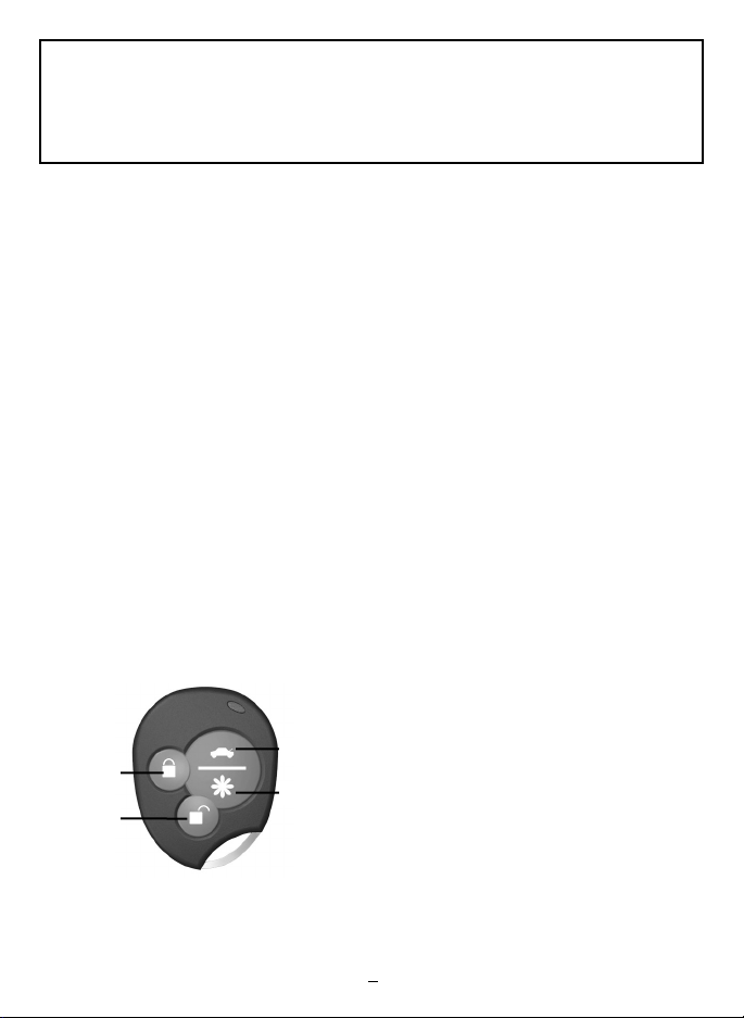
REMOTE TRANSMITTER LAYOUT
Button 2
Button 1
3
Button
NOTE:Transmitter cosmetics may differ, but
button functions remain the same.
Button
SYSTEM OPERATION
REMOTE LOCKING
To lock the doors press button 1:
• The horn will beep once. *
• The parking lights will flash once.*
• The doors will lock.
• The LED will turn solid for 10 seconds
then start flashing slowly.
• The optional starter defeat will
engage.*
* Optional Feature.
The optional Starter Defeat feature disables
the vehicle’s starter until button 2 is pressed,
or until the Emergency Override is
performed.
If the optional Ignition Trigger feature is
programmed, turning on the ignition before
pressing button 2 to unlock the doors will
cause the horn to honk and the lights to
flash for 30 seconds. Press button 2 to
disarm the ignition trigger and allow the
vehicle to start.
REMOTE UNLOCKING
To unlock the doors press button 2.
• The horn will beep twice.*
• The parking lights will flash twice.*
• The doors will unlock.
4
• The dome light will turn on.*
* Optional Feature.
NOTE: If the optional two-step unlock
feature is installed, pressing button 2 will
unlock only the driver’s door. Press button 2
again to unlock all remaining doors.
1

PASSIVE STARTER DEFEAT
If the optional starter defeat is installed, the
system can be programmed to automatically
disable the starter 45 seconds after turning
off the ignition as an extra measure of
security in the event the vehicle is
accidentally left unlocked. During the 45
second countdown, the LED will flash rapidly
to indicate the passive starter defeat
sequence has begun. After 45 seconds, the
LED will flash slowly and the vehicle’s starter
will be disabled.
IGNITION TRIGGER
After the system is remotely locked, turning
on the ignition before remotely unlocking
the system activates the optional ignition
trigger feature (if selected during
installation). The horn will honk and the
parking lights will flash for 30 seconds. To
deactivate the feature once triggered, press
button 2 on the transmitter or use the
override procedure (see below).
Turn on the ignition, then press the
override/valet switch for two seconds. The
starter defeat will disengage and the system
will enter valet mode.
VALET MODE
When the system is placed into valet mode,
the optional starter defeat, ignition trigger,
and passive starter defeat will be disabled.To
put your system into valet mode, turn the
ignition on and hold the override/valet
switch for 3 seconds. The horn will chirp
once (if installed) and the LED will turn on
solid to confirm valet mode. To exit valet
mode, repeat the same procedure. The horn
will chirp twice and the LED will turn off to
confirm valet mode exit.
AUXILIARY OUTPUT
The auxiliary output may be used to activate
an optional feature such as trunk release.
Press and hold button 3 for three seconds to
activate.
HORN OUTPUT
If the optional Horn Honk feature is
connected, the horn will provide
confirmation chirps when locking or
unlocking the doors, or when the Panic
feature is activated.
REMOTE PANIC
If the optional horn honk output is installed,
pressing button 4 for three seconds will
trigger the Panic mode. The horn will honk
and parking lights will flash for 30 seconds, or
until button 4 is pressed again.
EMERGENCY OVERRIDE
If the optional starter defeat is installed and
your remote is lost or fails to operate, you
can manually override the starter defeat.
2
ILLUMINATED ENTRY
The optional Illuminated Entry turns on the
dome light when the doors are remotely
unlocked. The dome light will remain on for
30 seconds or until the ignition is turned on.
LED STATUS MODES
Locked = Slow flash
Disarmed = Off
Passive Starter Defeat Warn = Rapid flash
Valet Mode = Solid

INSTALLATION INSTRUCTIONS
Before you begin the installation:
• This product must be installed by qualified
personnel according to these instructions.
• Verify with the customer the desired
location for the program switch and LED.
• Always use a multimeter when verifying
vehicle wiring.
Installation Notes:
• Do not install the main unit in the engine
compartment.
• Make all wiring connections to the vehicle
before connecting the main 15-pin
connector harness to the main unit.
• Mount the main unit in a secure area, away
from vehicle computers and heating/air
conditioning ducts. Mount the unit as far
away from metal objects as possible to
increase the range of the remote
transmitters.
• When running the harness wires through
the vehicle, be careful to run them where
they cannot be damaged or shorted. Keep
them away from any moving parts or areas of
high heat. Use rubber or plastic grommets to
protect the harness wires where they pass
through holes in metal panels.
Main Harness:
• BLACK WIRE - Ground input (-). Connect to
a
solid chassis ground that is clean and free
of paint or dirt.
• RED WIRE - +12V battery input.
• WHITE WIRE - Parking light output (+).
Connect to the wire that shows +12V when
the parking lights are on. If the vehicle’s
parking light circuit exceeds 10A, a relay is
required. For vehicle’s with independent left
and right parking light circuits, the parking
light wires must be connected using diodes
to keep the circuits separate.
• WIRE - Unlock #87 normally open input
10A fuse. (see Door Lock Wiring Diagrams)
• BLUE/BLACK WIRE - Unlock #30
common output. (see Door Lock Wiring
Diagrams)
• BROWN/BLACK WIRE - Unlock #87A
normally closed input. (see Door Lock Wiring
Diagrams)
• VIOLET/BLACK WIRE - Lock #87
normally open input 10A fuse. (see Door Lock
Wiring Diagrams)
• GREEN/BLACK WIRE - Lock #30
common output. (see Door Lock Wiring
Diagrams)
• WHITE/BLACK WIRE - Lock #87A
normally closed input. (see Door Lock Wiring
Diagrams)
• ORANGE WIRE - Armed Output (-)
500Ma. The ORANGE wire provides ground
when the unit is armed to activate a starter
disable relay. Connect to a relay for starter
defeat.. (See Relay Wiring Diagrams)
• BLACK/YELLOW - Dome light output (-)
500mA. Connect to a relay to activate the
dome light when the system is unlocked.(See
Relay Wiring Diagrams)
• GRAY WIRE - Auxiliary output (-) 500mA.
Connect to a relay for optional trunk release
etc. (See Relay Wiring Diagrams)
• BROWN WIRE - Horn honk output (-)
500mA. Connect to a relay to honk the
vehicle’s horn. (See Relay Wiring Diagrams)
3

• BLUE/WHITE WIRE - Passenger unlock
output (-) 500mA. The BLUE/WHITE wire
provides a ground to unlock the passenger
doors when the unlock button on the
transmitter is pressed two times. To install
the two-step unlock feature, the
BLUE/BLACK and BROWN/BLACK wires
must be run directly to the driver’s door
actuator unlock wire and the BLUE/WHITE
wire must be connected to a relay to unlock
the passenger doors. (see Optional Two-Step
Unlock Diagrams)
• YELLOW WIRE - Ignition input (+).
Connect to the main ignition wire that
switches +12V and does not drop out during
cranking.
2-Pin Red Connector: Plug-in connector
port for LED. Mount LED in an area where
it may be easily seen from either side of the
vehicle.
2-Pin Blue Connector: Plug-in connector
port for program/service switch. Mount
program switch in an area that is easily
accessible from the driver’s position.
PROGRAMMABLE FEATURES
To enter program mode:
1. Turn on ignition.
2. Within 5 seconds, press valet switch 5
times.
• The horn will provide a long chirp, to
indicate entering program mode.
3. Press the valet switch the number times
equal to the desired feature.
• The horn will chirp and lights/LED will
flash, each time the valet switch is
pressed.
4. Within 5 seconds, press the transmitter
button corresponding to the desired
operating mode for that feature.
• The horn will chirp and lights will flash
to indicate the setting.
One chirp/flash = Button 1
Two chirps/flashes = Button 2
5. Turn off ignition to save changes.
FEATURE DESCRIPTION
1. Ignition Lock/Unlock. Automatically
locks the doors when the ignition is turned
on and unlocks when the ignition is turned
off.
2. Door Unlock Pulse. Selects between a
single or double unlock pulse.
3. Chirp Mode. Selects or bypasses the
system’s lock’unlock confirmation chirps.
4. Door Lock PulseLength. Selects
between a .75-second or 3-second
lock/unlock pulse.
5. Passive Starter Defeat. Enables the
starter defeat to automatically activate 45
seconds after turning off the ignition.
6. Ignition Trigger. Enables the ignition
trigger feature when the system is remotely
locked.
Remote Programmable Features:
Step Function Button 1 (Default) Button 2
1. Ignition Controlled Door Locks On Off
2. Door Unlock Pulse Single Double
3. Chirp Mode Standard Silent
4. Door Lock Pulse Length .75 Seconds 3 Seconds
5. Passive Starter Defeat Enable Off On
6. Ignition Trigger Feature Off On
4

DEFAULT RESET
To reset all programmable features to their
factory default settings:
1. Turn on ignition.
2. Within 5 seconds, press valet switch 5
times.
• The horn will provide a long chirp, to
indicate entering program mode.
3. Press transmitter button 3.The LED will
flash 3 times, pause then continue
flashing. All programmable features will
be reset to the default position.
ADDING / DELETING REMOTE
TRANSMITTERS
Adding new transmitters to the system will
automatically delete all other remotes that
were previously operating the system.
NOTE: You must code all desired remotes
at this time.The unit can learn a maximum of
three transmitters.
To enter Code Learning Mode:
1. Turn ignition key on, off, on, off, on and
leave on within 5 seconds.The horn will
chirp (if installed) and the LED / parking
lights will flash once.
2. Press and hold valet switch for 3
seconds.The horn will chirp and the LED
/ parking lights will flash 3 times.
3. Release the program switch.
4. Program all desired remotes by pressing
button 1 on each of the transmitters.
The parking lights will flash after the
system has learned each remote control.
5. Turn ignition key off. Remotes are now
programmed to the system.
5

FACTORY
DOOR LOCK
RELAYS
NOT USED
NOT USED
FACTORY
DOOR LOCK
SWITCH
VIOLET
BLUE/BLACK
BROWN/BLACK
VIOLET/BLACK
GREEN/BLACK
WHITE/BLACK
(-) DOOR LOCK
(-) DOOR UNLOCK
HARNESS
FACTORY
DOOR LOCK
RELAYS
NOT USED
NOT USED
FACTORY
DOOR LOCK
SWITCH
VIOLET
BLUE/BLACK
BROWN/BLACK
VIOLET/BLACK
GREEN/BLACK
WHITE/BLACK
(+) DOOR LOCK
(+) DOOR UNLOCK
HARNESS
CONNECT
TO +12V
VIOLET
BLUE/BLACK
BROWN/BLACK
VIOLET/BLACK
GREEN/BLACK
WHITE/BLACK
CONNECT
TO +12V
AFTER-MARKET
ACTUATORS
HARNESS
VACUUM PUMP
LOCK/UNLOCK
SWITCH
VIOLET
BLUE/BLACK
BROWN/BLACK
VIOLET/BLACK
GREEN/BLACK
WHITE/BLACK
CONNECT
TO +12V
CUT
X
L
UL
HARNESS
VIOLET
BLUE/BLACK
BROWN/BLACK
VIOLET/BLACK
GREEN/BLACK
WHITE/BLACK
CONNECT
TO +12V
LOCK/UNLOCK
SWITCH
CUT
FACTORY DOOR
MOTOR
CUT
X
X
L
UL
HARNESS
DOOR LOCK WIRING DIAGRAMS
NEGATIVE PULSE DOOR LOCK SYSTEM POSITIVE PULSE DOOR LOCK SYSTEM
ADDING ACTUATORS
VACUUM DOOR LOCK SYSTEM
REVERSE POLARITY DOOR LOCK SYSTEM
6

BLUE/WHITE
VIOLET
BLUE/BLACK
BROWN/BLACK
VIOLET/BLACK
GREEN/BLACK
WHITE/BLACK
LOCK/UNLOCK
SWITCH
CUT
DRIVER'S DOOR
MOTOR
PASSENGER DOOR
MOTORS
X
(-) DOOR LOCK
(-) DOOR UNLOCK
L
UL
HARNESS
FACTORY DOOR
LOCK MODULE
CONNECT
TO +12V
CONNECT
TO +12V
BLUE/WHITE
86
30
87
87a
85
VIOLET
BLUE/BLACK
BROWN/BLACK
VIOLET/BLACK
GREEN/BLACK
WHITE/BLACK
LOCK/UNLOCK
SWITCH
CUT
DRIVER'S DOOR
MOTOR
PASSENGER DOOR
MOTORS
X
(+) DOOR LOCK
(+) DOOR UNLOCK
L
UL
HARNESS
FACTORY DOOR
LOCK MODULE
CONNECT
TO +12V
VIOLET
BLUE/BLACK
BROWN/BLACK
VIOLET/BLACK
GREEN/BLACK
WHITE/BLACK
CONNECT
TO +12V
DRIVER'S DOOR
MOTOR
PASSENGER DOOR
MOTORS
CUT
CUT
X
X
CUT
X
LOCK/UNLOCK
SWITCH
HARNESS
BLUE/WHITE
CONNECT
TO +12V
L
UL
86
30
87
87a
85
VIOLET
BLUE/BLACK
BROWN/BLACK
VIOLET/BLACK
GREEN/BLACK
WHITE/BLACK
CONNECT
TO +12V
DRIVER'S DOOR
ACTUATOR
HARNESS
86
30
87
87a
85
PASSENGER DOOR
ACTUATORS
BLUE/WHITE
CONNECT
TO +12V
OPTIONAL TWO-STEP UNLOCK WIRING DIAGRAMS
TWO-STEP UNLOCK
NEGATIVE PULSE
TWO-STEP UNLOCK
POSITIVE PULSE
TWO-STEP UNLOCK
REVERSE POLARITY
TWO-STEP UNLOCK
ADDING ACTUATORS
7

Black Ground (-)
Valet Switch
LED
Violet Unlock #87 Normally Open input [10A fuse]
Blue/Black Unlock #30 Common output
Brown/Black Unlock #87a Normally Closed output
Violet/Black Lock #87 Normally Open input [10A fuse]
Green/Black Lock #30 Common output
White/Black Lock #87a Normally Closed output
Orange Starter Defeat output (-) 500mA
Black/Yellow Dome Light output (-) 500mA
Gray Auxiliary output (-) 500mA
Brown/White Horn Honk output (-) 500mA
Blue/White Passenger Unlock Output (-) 500mA
Red +12V Battery input (+) [15A fuse]
White Parking Light output (+) [10A fuse]
Yellow Ignition input (+)
KEYLESS ENTRY WIRING DIAGRAM
ORANGE
WIRE
TO
STARTER
IGNITION
SWITCH
CUT
X
CONNECT
TO +12V
86
30
87
87a
85
HORN OR DOME
LIGHT OUTPUT
FROM ALARM
TO POSITIVE HORN HONK
OR DOME LIGHT WIRE
CONNECT
TO +12V
86
30
87
87a
85
RELAY WIRING DIAGRAMS
STARTER DEFEAT
TRUNK RELEASE DIAGRAM
TO TRUNK RELEASE WIRE
87
87a
86
85
30
CONNECT
TO +12V
GRAY
WIRE
HORN HONK / DOME LIGHT DIAGRAMS
TO POSITIVE HORN HONK
© 2005 64-854 Rev 2 6/05
8
HORN OR DOME
LIGHT OUTPUT
FROM ALARM
OR DOME LIGHT WIRE
87
87a
86
85
30
CONNECT
TO +12V
 Loading...