

Page 1
1
REMOTE AUTOSTART SYSTEM
WITH KEYLESS ENTRY AND NETWORK INTERFACE
Before You Begin
This system is intended for installation on vehicles equipped with automatic transmissions and
electronic fuel injection only! DO NOT INSTALL
THIS SYSTEM INTO A MANUAL TRANSMISSION VEHICLE AS IT COULD RESULT IN SERIOUS INJURY OR DEATH.
• This product must be installed by qualified
personnel according to these instructions and
and observing all safety features.
• Verify that the vehicle is equipped with electronic fuel injection and automatic transmission.
• Check to see if the vehicle is equipped with
any type of factory security system.
• Check to see if there is a pin switch for the
hood, if not one must be installed.
• Verify that the vehicle starts and idles properly before starting the installation.
• Always use a multi-meter when verifying
vehicle wiring.
• Before mounting the product, verify with the
customer the desired location for the valet
switch and LED.
• Set the Polarity Jumper inside the main unit
first. (see Jumper Settings, Page 12)
High-Current Wire Connections:
• RED WIRE #1 -Main power input; using the
supplied inline fuse holder, connect directly to
the vehicle’s battery or alternate power source
with a minimum 30 Amp supply.
• RED WIRE #2 - Secondary power input; see
above. Note: If not connecting directly to the
vehicle’s battery,it is recommended to use separate power sources (minimum 30 Amp each) for
each red power wire.
• BROWN WIRE - Second ignition output;
connect to the wire that switches +12V and
does not drop out during cranking. This wire
may be optionally programmed for use as a second accessory wire or second starter wire. (see
Programmable Features,Page 4)
• ORANGE WIRE - Main accessory output;
+12V output to heater and/or air conditioning
system. For cars with more than one accessory
wire add a relay(s) to power the extra accessory wire(s) or program the BROWN wire for
second accessory.
• YELLOW WIRE - Main ignition output;
connect to the main ignition wire that switches
+12 V and does not drop out during cranking.
• VIOLET WIRE - Starter output;connect to the
vehicle’s starter wire.
BEFORE INSTALLING THIS PRODUCT PLEASE READ
THIS INSTALLATION MANUAL THOROUGHLY!!
INSTALLATION MANUAL
Page 2

Main Harness:
• GREEN/WHITE WIRE - Brake switch input
wire. Connect this wire to the brake switch
wire that provides +12V when the brake pedal
is pressed. This is a safety input and must be
connected on all installations.
• BLACK/GRAY WIRE - Tachometer input. If
the Smart Start feature fails to start properly,
connect the BLACK/GRAY wire directly to the
vehicle’s tach wire or negative fuel injector wire,
and program Step #14 to Tach Start.
• WHITE/RED WIRE - Auxiliary 2 output (-)
500mA. Connect to a relay or module for an
optional feature such as power window
activation, etc.This output may be programmed
for momentary,timed, or latched operation.
• BLACK/WHITE WIRE - Dome Light output () 500mA. Connect to a relay to activate the
vehicle’s dome light. NOTE: The dome light
relay’s output is usually connected to the same
wire used for the door trigger input (See
GREEN and VIOLET door trigger wires).
• YELLOW WIRE - +12V Ignition input.
Connect to a main ignition wire at the ignition
switch harness.This wire shows +12V when the
ignition is on and while cranking. The voltage
must not drop when the car is starting.
• BLUE/YELLOW WIRE - Glow Plug input (+).
For diesel engines connect to the glow plug wire
in the instrument cluster that shows +12V when
the the glow plug (wait-to-start) light is on, then
shows ground when the light turns off. For
vehicle’s equipped with a negative glow plug
wire (shows ground when the wait-to-start light
is on) a relay is required. (see Relay Diagrams)
• BLUE/WHITE WIRE - Passenger Unlock
output (-) 500mA. Connect to an optional relay
to unlock the passenger doors when the system
is configured for Driver Priority Unlocking.
• BLUE/ORANGE WIRE - Ground When
Running Output (-). This wire provides a ground
when the remote start is engaged to activate an
optional factory security bypass module.
• BLACK WIRE - Ground input (-).Connect to
a solid chassis ground that is clean and free of
paint or dirt.
• RED WIRE - +12V Battery input #3. Connect
the red fused wire on the main harness to a
constant +12V source. This wire is the power
input for the module.
• VIOLET WIRE - Positive door trigger (+).
Connect to the door switch circuit wire that
shows +12V when the door is open. This type
of door circuit is usually found on Ford vehicles.
• GREEN WIRE - Negative door trigger (-).
Connect to the door switch circuit wire that
shows ground when the door is open.
• WHITE/BLACK WIRE - Hood switch input
wire (-). Connect this wire to the hood pin
switch to prevent the vehicle from starting if the
hood is open.This is a safety input and must be
connected on all installations.
• ORANGE WIRE - Locked output (-) 500mA.
Connect to a relay for optional starter defeat
and anti-grind protection. (See Relay Diagrams).
• VIOLET/WHITE WIRE - Factory Disarm
output (-). Connect to the wire that requires a
ground pulse to disarm the factory alarm. The
VIOLET/WHITE wire provides a ground pulse
when the remote transmitter is used to unlock
the doors or start the vehicle.
• WHITE/VIOLET WIRE - Factory Arm
output (-). Connect to the wire that requires a
ground pulse to arm the factory alarm. The
WHITE/VIOLET wire provides a ground pulse
when the remote start shuts down.
• BROWN WIRE - Audible status output (+) 3A.
Connect an optional siren for lock/unlock chirps.
2
Page 3

• GRAY WIRE - Auxiliary 1 output (-) 500mA.
Connect to a relay for optional features such as
trunk release, etc. This output is programmable
for momentary, timed, or latched operation.
• WHITE WIRE - Parking Light output (+/-)
10A relay. Connect to the vehicle’s parking light
wire.If the vehicle’s parking light circuit exceeds
10 Amps a relay is required. For vehicle’s with
independent left and right parking light circuits,
the parking light wires must be connected using
diodes to keep the circuits separate.NOTE:Do
not connect the WHITE wire to the vehicle’s
headlight circuit.
• BROWN/WHITE WIRE - Horn output (-)
500mA. Connect to an optional relay to acti-
vate the vehicle’s horn. This wire is also programmable for use as a 3rd ignition output if
necessary (optional relay required).
Plug-in Connectors
4-Pin White Connector: Auxiliary Start inputs.
F
or add-on start module installation only.
• WHITE WIRE - 3 pulse start input (-).
Connect to the door lock wire of an OEM
security/keyless entry system. Pressing the system’s lock button 3 times within 3 seconds will
start the vehicle.
• BLACK WIRE - Not Used.
• BLUE WIRE - Auxiliary start input (-).
Connect to the auxiliary output wire from an
aftermarket security system.
• RED WIRE - Not Used.
2-Pin Blue Connector: Plug-in connector for
Valet switch. Mount the switch in an area that
is easily accessible from the driver’s position.
2-Pin Red Connector: Plug-in connector for
LED. Mount LED in an area where it may be
easily seen from either side of the vehicle.
3-Pin White Door Lock Connector: Plug-in
connector for door lock harness or optional
door lock relay module (PDLM-3).
• BLUE WIRE - Unlock output (-) 500mA.
• RED WIRE - Relay trigger only (+) 300mA.
Low current output for relay modules,or inverters. Do NO
T use as a power source for door
lock relays.
• GREEN WIRE - Lock output (-) 500mA.
3-Pin White Network Connector: The plug-in
network connector port is on the side of the
main module. This network port may be used
with the optional personal computer interface
for diagnostics, software customization and
expanded programming options. The network
also offers connection to optional accessories.
Entering Programming
To enter System Programming:
1. Turn on ignition.
2. Within 5 seconds, press valet switch 5
times.
• The lights will flash 3 times, indicating that
you have entered Programming.
3. Press the valet switch the number times
equal to the Feature you want to change.
• The lights will flash each time the valet
switch is pressed.
4. Within 5 seconds, press the transmitter
button corresponding to the desired operating mode for that Feature.
• The lights will flash to indicate the setting.
One flash = Button 1
Two flashes = Button 2
Three flashes = Button 3
5. Repeat steps 3 and 4 to change additional
features.
6. Turn off ignition to save changes.
• The lights will flash once to confirm exit.
Note: The optional FM transmitter may not be
used for feature programming.
3
Page 4

Programmable Features
1. Ignition Locking. Automatically locks the
doors when the ignition is turned on. The system will not lock the doors if any door is open
when the ignition is turned on.
2. Ignition Unlocking. Automatically unlocks
the doors when the ignition is turned off. Select
from all door unlock, driver's door only unlock,
or no unlock. (Note: Driver’s door only unlock
requires wiring the system for Passenger
Unlock. see Two Step Unlocking Diagrams.)
3. Door Unlock Pulse - Single/Double. Selects
between a single pulse or a double pulse door
unlock output.
4. Door Lock Pulse Width. Selects between a
1-second and a 3-second output for vehicles
equipped with vacuum door locking systems.
5. Auxiliary 2 Auto Activate on Lock. When
selected, the Auxiliary 2 output will activate
when the Lock button is pressed.
6. Auxiliary Function I - Selectable for
Momentary,Timed, or Latched operation.
When Momentary operation is selected, the
system will provide an output for as long as the
Transmitter button is held.
When Latched operation is selected, the system
will provide an output that turns on when the
transmitter button is pressed and turns off
when the transmitter button is pressed again.
When Timed operation is selected, the system
will provide an output that turns on for 10 seconds each time the transmitter button is
pressed. If the button is pressed again during
the 10 seconds, the output will turn off.
7. Auxiliary Function 2 - Selectable for
Momentary,Timed, or Latched operation.
8. Not Used.
9. Remote Start in Valet Mode. Determines if
remote start operates while in valet mode.
10. Not Used.
11. Not Used.
12. Engine Run Time. Selects between 12 and
24 minute run cycle.
13. Cold Temperature Starting. Allows the
vehicle to automatically start and run every 2
hours or every hour for severe cold weather.
14. Engine Start Sense. Selects between Smart
Start for tachless operation, or Tach Start for
actual RPM monitored starting. (see Step #15
and Engine Programming for Remote Start below)
15. Engine Programming. Pressing transmitter
button I "learns" the RPM. For diesel vehicles,
after learning Tach signal enter step #15 again
and set for diesel by pressing button 3. (see
Engine Programming for Remote Start below)
16. FM Transmitter Module. Pressing Button 1
learns the add-on FM module ID for FM transmitter compatibility. Pressing button 2 allows FM
transmitter learning. After pressing button 2 on
the AM remote, press transmitter button 1 on
each FM remote (max 2).
17. Ignition 2 Relay Programming. Selects
between second ignition, second accessory, or
second starter output operation for heavy
gauge BROWN wire.
18. Horn Output. Selects between horn output
or ignition 3 output for the horn wire.
Engine Programming for Remote Start
In order for the system to properly start and
run the vehicle, the unit must be able to determine if the engine is cranking or if the engine
is actually running.This system is equipped with
two means of detecting the engine’s run status:
Smart Start and Tach Start.
The Smart Start feature detects the engine’s
run status by interpreting certain characteristics
of the engine, without requiring connection to
the vehicle’s tachometer wire. This feature
allows faster installation, but may not work with
all vehicles, or in extreme temperatures.
4
Page 5

The Tach Start feature requires connection to
the vehicle’s tachometer wire, or an injector (-)
wire if the tach wire is not available. The Tach
Start feature provides reliable operation with
virtually any vehicle and in severe temperature
extremes. When Tach Start is selected,the vehicle’s tach signal must be “learned” through system programming. (see below)
To Program the Tach Start feature:
1. Enter System Programming. (see Entering
Programming)
2. Program Step #14 to Tach Start using transmitter button 2.
3. Re-enter system programming, and go to
Step #15.
4. Immediately start the vehicle with the key to
avoid the programming sequence timing out.
5. Press transmitter button 1 to learn the vehicle’s tach signal.
• The LED will flash once if the tach was
learned.
• The LED will flash 5 times if the tach was
not learned.
6. Turn off ignition to save settings.
The default setting for the engine mode is Gas
Engine. For diesel vehicles,the engine type for
Step #15 must be set to Diesel Engine. When
programmed for diesel engines, the BLUE/YELLOW wire (glow plug input) is monitored to
make sure the glow plugs have warmed up
before the engine begins cranking. If the glow
plug wire is not connected, the unit has a builtin timer that waits 15 seconds before cranking
the starter.
5
Programmable Features
Step Function Button 1 Button 2 Button 3
1. Ignition Locking On Off
2. Ignition Unlocking All Doors Driver only Off
3. Door Unlock Pulse Single Double
4. Door Lock Pulse Width 1 second 3 seconds
5. Auxiliary 2 Auto Activate on Lock Off On
6. Auxiliary 1 Output Momentary 10 seconds Timed Latched
7. Auxiliary 2 Output Momentary 10 seconds Timed Latched
8. Not Used
9. Remote Start in Valet Mode Disabled Enabled
10. Not Used
11. Not Used
12. Engine Run Time 12 minutes 24 minutes
13. Cold Temperature Starting Every 2 hours Every hour
14. Engine Start Sense Smart Start Tach Start
15. Engine Programming Learn RPM Gas Engine Diesel Engine
16. FM Module Program (optional) Learn Module Learn FM Transmitter
17. Ignition 2 Relay Programming Ignition 2 Accessory 2 Starter 2
18. Horn Output Horn Output Ignition 3 Output
Page 6

Complete Default Reset
Following this procedure will set all
Programmable Features to factory default settings.
1. Enter System Programming.
2. Press Transmitter Button 3.
• The lights will flash 6 times indicating the
reset signal was received.
• All Programming options are now set to
factory default settings.
3. Turn ignition off.
Adding Transmitters
To add a new transmitter to the system have the
desired transmitters ready and follow the Code
Learning sequence.
To enter Code Learning Mode:
1. Turn the ignition on, off, on, off and leave on.
• The lights will flash 3 times.
2. Press the Valet switch.
• The status LED will turn on red.
• The lights will flash 5 times.
3. Press the Lock Button on the transmitter.
• The lights will flash once.
4. Press Lock Button on the transmitter again.
• The lights will flash twice.
5. Repeat steps 3 and 4 for each additional
transmitter.
6. Turn off the ignition.
• The lights will flash 3 times.
Factory Theft Deterrent Systems
Many newer vehicles are factory-equipped with
anti-theft systems that disable the fuel system
unless a properly coded key is inserted into the
ignition cylinder. In these vehicles, first determine the type of anti-theft system, then install
the proper bypass module.
General Motors Anti-theft Systems:
Many late-model GM vehicles are equipped with
one of three basic anti-theft systems; Passkey,
Passlock, and Passkey 3. Standard Passkey
systems are easily identified by the resistor chip
visible on the shaft of the key. Passlock systems
use a normal key,but feature an ignition cylinder
that generates a resistance code when the key is
turned to start the vehicle. To properly interface
into these systems and retain full functionality of
the factory anti-theft system, a VATS/PASSLOCK
bypass module must be installed.
The Passkey 3 system, which is found on GM
vehicles 1999 and newer, is a transponder based
system described below.
Passive Transponder Systems:
Passive transponder systems (commonly found
on late model Ford, Honda, Chrysler, Toyota,
Nissan and other vehicles) feature a tiny passive
transmitter housed in the base of the key. This
passive device activates when placed close to the
vehicle’s ignition switch, sending a signal that
enables the vehicle’s fuel delivery system. If the
transponder key is not detected, the starter
will crank but the fuel system will be disabled,
not allowing the vehicle to run. To properly
interface these systems, a transponder
bypass module must be installed. These
modules allow full functionality of the factory
anti-theft system and may require the use of a
spare key.
6
Page 7

7
HORN HONK DIAGRAMS
TRUNK RELEASE DIAGRAM
RELAY WIRING DIAGRAMS
87
8586
87a
30
x
x
CUT
YELLOW
IGNITION +12V
TO STARTER
MOTOR
TO BATTERY
VIOLET
STARTER WIRE
ORANGE
ARMED OUTPUT
IGNITION
SWITCH
STARTER DISABLE / ANTI-GRIND
WHITE/RED
AUX 2
OUTPUT
87
86 85
87a
30
+12V
TO HEAD LIGHT WIRE
OPTIONAL HEADLIGHT ACTIVATION
Program the Auxiliary 2 output for timed operation
and the headlights will turn on with Aux 2 for the preset timer duration then automatically turn off.
Program the Auxiliary 2 output for latched operation
and the headlights will turn on with Aux 2 and remain
on until the Auxiliary 2 function is pressed again.
(-) GLOW PLUG
WIRE FROM
VEHICLE
YELLOW
IGNITION +12V
BLUE/YELLOW
87
86 85
87a
30
+12V
NEGATIVE GLOW PLUG
BLACK/WHITE
DOME LIGHT
OUTPUT
87
86 85
87a
30
+12V
TO POSITIVE DOME LIGHT WIRE
BLACK/WHITE
DOME LIGHT
OUTPUT
TO NEGATIVE DOME LIGHT WIRE
87
86 85
87a
30
+12V
DOME LIGHT DIAGRAMS
Page 8

8
FACTORY
DOOR LOCK
RELAYS
(+) DOOR LOCK
(+) DOOR UNLOCK
LOCK/UNLOCK
SWITCH
L
UL
86
30
87
87a
85
86
30
87
87a
85
GREEN
BLUE
+12V
NEGATIVE PULSE LOCK SYSTEM
POSITIVE PULSE LOCK SYSTEM
ADDING ACTUATORS VACUUM LOCK SYSTEM
DOOR LOCK WIRING DIAGRAMS
REVERSE POLARITY LOCK SYSTEM
Page 9

9
LOCK/UNLOCK
SWITCH
CUT
DRIVER'S DOOR
MOTOR
PASSENGER DOOR
MOTORS
X
(+) DOOR LOCK
(+) DOOR UNLOCK
L
UL
BLUE/WHITE
GREEN
86
30
87
87a
85
BLUE
86
30
87
87a
85
+12V
86
30
87
87a
85
FACTORY DOOR
LOCK MODULE
TWO-STEP UNLOCK
NEGATIVE PULSE
TWO-STEP UNLOCK
POSITIVE PULSE
TWO-STEP UNLOCK
REVERSE POLARITY
TWO-STEP UNLOCK
ADDING ACTUATORS
OPTIONAL TWO-STEP UNLOCK WIRING DIAGRAMS
Page 10
10
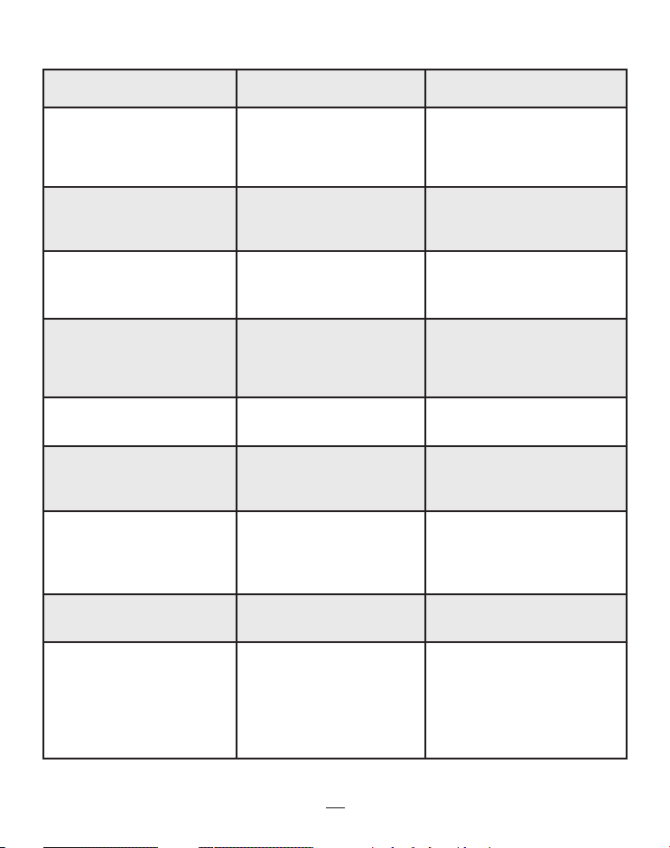
TROUBLESHOOTING
Problem
Range is poor.
Vehicle will not remote start.
Vehicle cranks and begins to
run, then shuts off.
Vehicle cranks but will not
run.
Keyless entry does not operate with remote.
Ignition triggered door lock
feature does not operate.
Car horn honks when system
disarmed and door is opened.
Car will not start and system
does not function properly.
Diesel vehicle cranks at incorrect time (before wait-to-start
light turns off or long after
light turns off,.
Probable Cause
Antenna wire is grounded;
Module is picking up interference from vehicle’s electrical
system.
Safety inputs are triggered.
System is in Valet mode.
Smart Start is not compatible
with this vehicle;Vehicle’s tach
signal is not learned.
Vehicle has a factory theft
deterrent system that prevents starting w/o key in ignition.
Wrong door lock polarity;
Wrong lock wires connected.
Yellow wire shows +12V;
Door is open; Door trigger
input wrong polarity.
Vehicle’s factory security system needs to be disarmed.
Vehicle battery dead or drops
below 9 volts during cranking.
Glow plug wire not connected; Glow plug wire connected
to wrong wire; Wrong glow
plug wire polarity.
Suggested Correction
Make sure antenna is not connected to ground; Relocate
module or route antenna away
from computer modules.
Check brake switch input (+)
or hood input (-). Exit Valet
mode.
Connect the BLACK/GRAY
wire, and program the unit to
learn the vehicle’s tach signal.
See Bypassing Factory Theft
Deterrent Systems.
See door lock diagram; Verify
vehicle lock/unlock wires.
Connect yellow wire to proper
ignition wire; Close door;
Change door trigger polarity.
Locate the disarm wire (usually located in driver’s kick panel)
and connect VIOLET/WHITE
wire to disarm factory system.
Charge or replace battery.
Connect BLUE/YELLOW wire
to glow plug wire; Connect to
correct glow plug wire in vehicle; Check glow plug wire
polarity and use a relay to
change (see Relay Diagrams).
Page 11

11
TROUBLESHOOTING CONTINUED
Problem
System will not enter Code
Learning Mode.
Parking lights do not flash.
Door locks do not lock or
unlock correctly, or action is
reversed
Illuminated Entry does not
activate on upon unlock.
Probable Cause
Ignition was not left in the on
position after turning it on &
off three times; Sequence not
performed rapidly enough (5
sec.); Valet switch is defective
or not plugged in.
Wrong wire connected,
Wrong polarity selected, or
RED Wire #1 not connected
to battery power.
Defective GREEN or BLUE
wire in door lock connector
plug, GREEN and BLUE wires
reversed, or wrong door lock
wiring diagram used.
External relay required, or
Wrong polarity wired for
relay.
Suggested Correction
Leave ignition in on position;
Repeat procedure quicker;
Replace valet switch.
Connect WHITE wire to
proper wire, Reverse jumper
polarity (see Jumper Settings),
Connect RED wire #1 to +12V.
Check GREEN and BLUE wires
on door lock connector plug;
Verify vehicle’s type of door
lock system; Reverse wiring to
door relays.
Add relay (see Relay Wiring
Diagrams; Reverse relay polarity.
Page 12
12
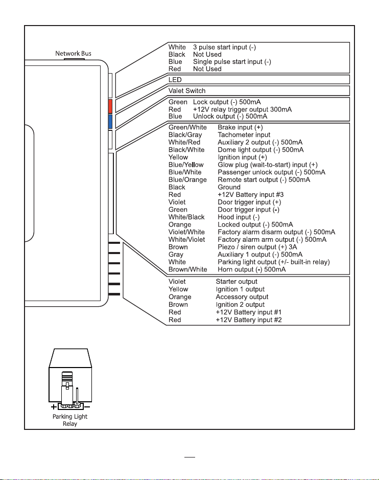
WIRING DIAGRAM
JUMPER SETTINGS
The output polarity for the built-in parking light relay is determined by the placement of the jumper on the 3 pins in front of
the relay. The default settings is illustrated on the left.
Jumper on Center Pin and Left Pin = Positive Output
Jumper on Center Pin and Right Pin = Negative Output
© 2002, DLC,INC.
64-550, 10/02 Rev. 1
 Loading...