

Blackmagicdesign Blackmagic MultiView 4, Blackmagic MultiView 16 Installation And Operation Manual
Page 1
Installation and Operation Manual
Blackmagic
MultiView
August 2016
English, 日本語, Français, Deutsch, Español,
中文, 한국어, Русский
and
Italiano.
Page 2

Languages
To go directly to your preferred language, simply click on the hyperlinks listed in the
contents below.
English 3
日本語
40
Français 78
Deutsch 116
Español 154
中文
한국어
Русский
192
230
268
Italiano 306
Page 3

Welcome
Thank you for purchasing Blackmagic MultiView!
We hope you share our dream for the television industry to become truly creative
by allowing anyone to have access to the highest quality video. By using MultiView16
with today’s affordable Ultra HD televisions, you get the equivalent of up to 16
independent broadcast monitors. MultiView 16 gives you true broadcast level multi
source monitoring at a fraction of the cost!
English
Blackmagic MultiView 4 is perfect for smaller or mobile productions, letting you
monitor up to four sources on a HD or Ultra HD screen. You can even combine
MultiViews by routing the output of one MultiView into another to really customise your
monitoringsetup!
This instruction manual contains all the information you’ll need to install your Blackmagic
MultiView, although it’s always a good idea to ask a technical assistant for help if you are
not sure what IP addresses are, or if you’re unsure about computer networks. Blackmagic
MultiView can be controlled using Videohub Control software which is easy to install,
however there are a few slightly technical preferences you will need to
set after you install it.
Please check our web site at www.blackmagicdesign.com and visit the support page
to download the latest updates to this manual and software. Lastly, please register
your Blackmagic MultiView when downloading software updates so we can keep you
updated when new software is released. We are constantly working on new features
and improvements, so we would love to hear from you!
We hope you get years of use from your Blackmagic MultiView and have lots of fun
viewing your video inputs in wonderful Ultra HD!
Grant Petty
CEO Blackmagic Design
Page 4

Contents
Blackmagic MultiView
Getting Started 5
Plugging in Power 5
Connecting SDI Sources and Monitors 5
Setting your Multi View Layout 6
Connecting to a Network 7
Connecting Serial Control 8
Rack Installation 8
Using Multiple MultiViews 8
Changing Settings 9
Blackmagic MultiView 16’s Front Control Panel 10
Changing Settings using TeranexMiniSmart Panel 15
Installing Teranex Mini Smart Panel 15
Teranex Mini Smart Panel Features 16
Control Buttons and Rotary Knob 16
Changing Settings using Teranex Mini Smart Panel 17
Changing Settings using Switches 19
Switch Settings 20
Using Blackmagic MultiView Setup 21
Installing Blackmagic MultiView Setup 21
Blackmagic MultiView Setup Home Page 22
Changing Settings using Blackmagic MultiView Setup 23
Sources 23
Views 24
Configure 24
Saving and Loading Label Sets 27
Updating the Internal Software 28
Using Videohub Control Software 28
Controlling Blackmagic MultiView using BlackmagicVideohub Control Software 29
Developer Information 30
Blackmagic Videohub Ethernet Protocol v2.3 30
Blackmagic MultiView 16 RS-422 Protocol 34
Help 37
Warnings 38
Warranty 39
Contents
Page 5
Getting Started
MultiView 4
Blackmagic
4
31
2
HDMI OUT
HD
UHD
OUT
SD/HD/3G/6G-SDI IN
MultiView 4
Blackmagic
Getting started with your Blackmagic MultiView is as easy as plugging in power, connecting
your SDI video sources, and plugging your monitors and televisions into the HDMI or SDI
outputs. This section of the manual will show you everything you need to know to get started
using your Blackmagic MultiView.
Plugging in Power
To power your Blackmagic MultiView, simply plug a standard IEC power cord into the 110-240V
AC power input on the rear panel.
TIP Blackmagic MultiView 4 can also accept Power over Ethernet Plus, which
means you only need to plug it into an Ethernet switch capable of supplying
PoE+. If you have both AC power and PoE+ connected to your MultiView 4,
itwill automatically switch to the remaining power supply if one is
unplugged or fails.
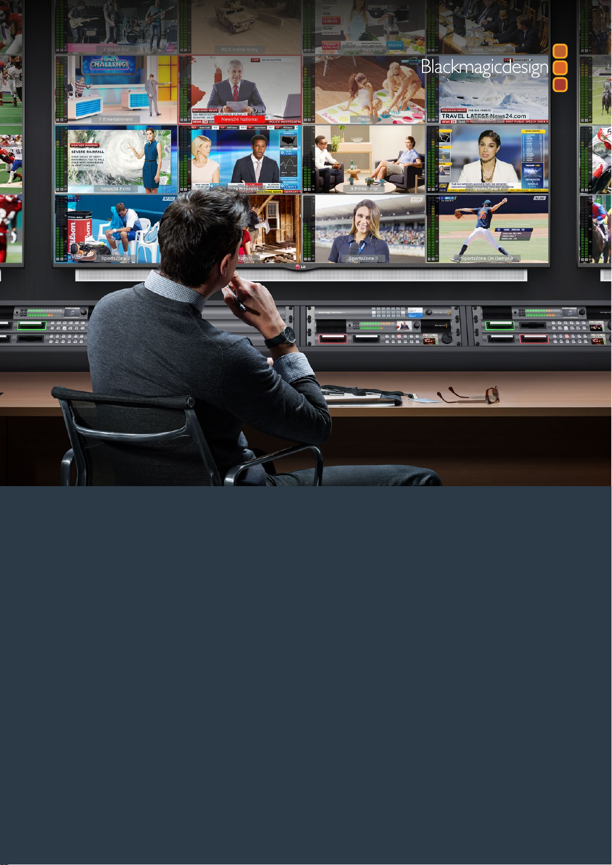
Connecting SDI Sources and Monitors
Plug your SDI sources into any of the SDI video inputs on the rear panel. The video format will
be automatically detected and displayed in the multi view output. To see the output, simply
connect a monitor to the HD, 6G-SDI or HDMI multi view outputs.
HD
UHD
OUT
31
SD/HD/3G/6G-SDI IN
4
HDMI OUT
2
ETHERNET
Connect the video sources to your Blackmagic MultiView’s SDI video inputs.
HD
UHD
OUT
HD
UHD
OUT
31
SD/HD/3G/6G-SDI IN
4
HDMI OUT
HDMI OUT
2
ETHERNET
Connect monitors to your Blackmagic MultiView’s HDMI or SDI multi view outputs.
When connecting an HDMI monitor to the HDMI output, your Blackmagic MultiView will
automatically detect whether the monitor supports Ultra HD or HD and switch the multi view
output accordingly.
TIP On Blackmagic MultiView 16 you can output the multi view via dedicated
HD-SDI outputs, or up to Ultra HD via the 6G-SDI and HDMI outputs.
55Getting Started
Page 6
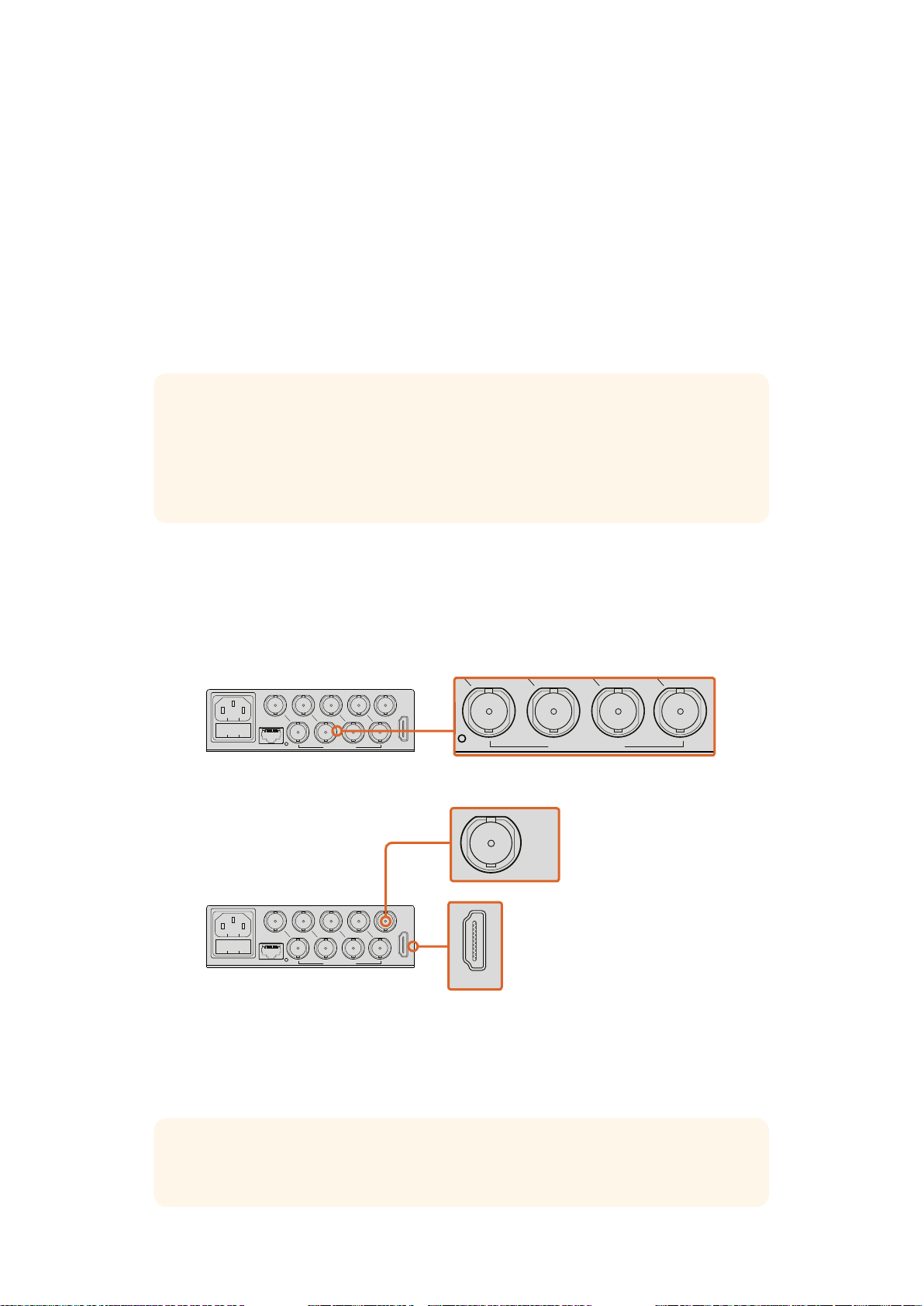
You can also connect your sources to other video equipment via the loop outputs above
LOOP OUT
IN
HDMI OUT 6G-SDI OUT HD-SDI OUT
HDMI OUT 6G-SDI OUT HD-SDI OUT
eachSDI input.
1 2 3 4 5 6 7 8 9 10 11 12 13 14 15 16
REF IN
RS-422
CNTRL
ETHERNET SD/HD/3G/6G-SDI IN
USB
TIP All of Blackmagic MultiView 16’s SDI and HDMI outputs can be used
simultaneously for Ultra HD and HD multi view monitoring. On
Blackmagic MultiView 4, you can select between Ultra HD or HD multi
view output settings using the built in switches, an optional Teranex Mini
Smart Panel, or via the Blackmagic MultiView Setup utility software.
Setting your Multi View Layout
LOOP OUT
IN
HDMI OUT 6G-SDI OUT HD-SDI OUT
The multi view layout can be changed to suit your needs. For example, Blackmagic MultiView 4
can be set to 2x2 or solo. Blackmagic MultiView 16 can be set to a combination of views such as
2x2, 3x3, 4x4 or solo.
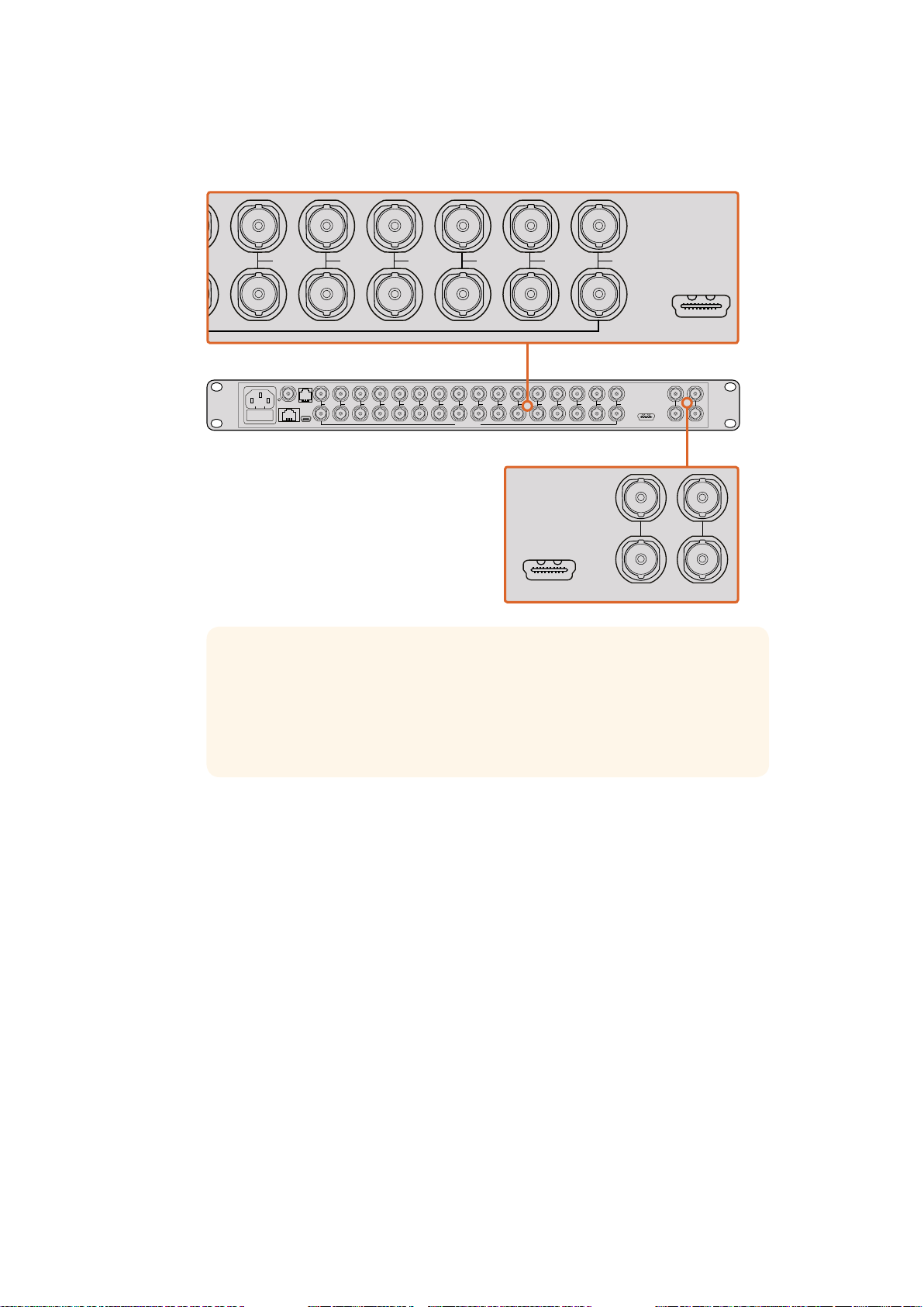
Setting your layout on Blackmagic MultiView 16
To change the layout on Blackmagic MultiView 16, use the control buttons, rotary knob and LCD
on the built in control panel. You can also monitor any view in full screen mode by pressing the
‘solo’ button, then selecting your chosen view by pressing the ‘view’ button.
1 Press the ‘menu’ button on the front control panel to open the settings screen
on the LCD.
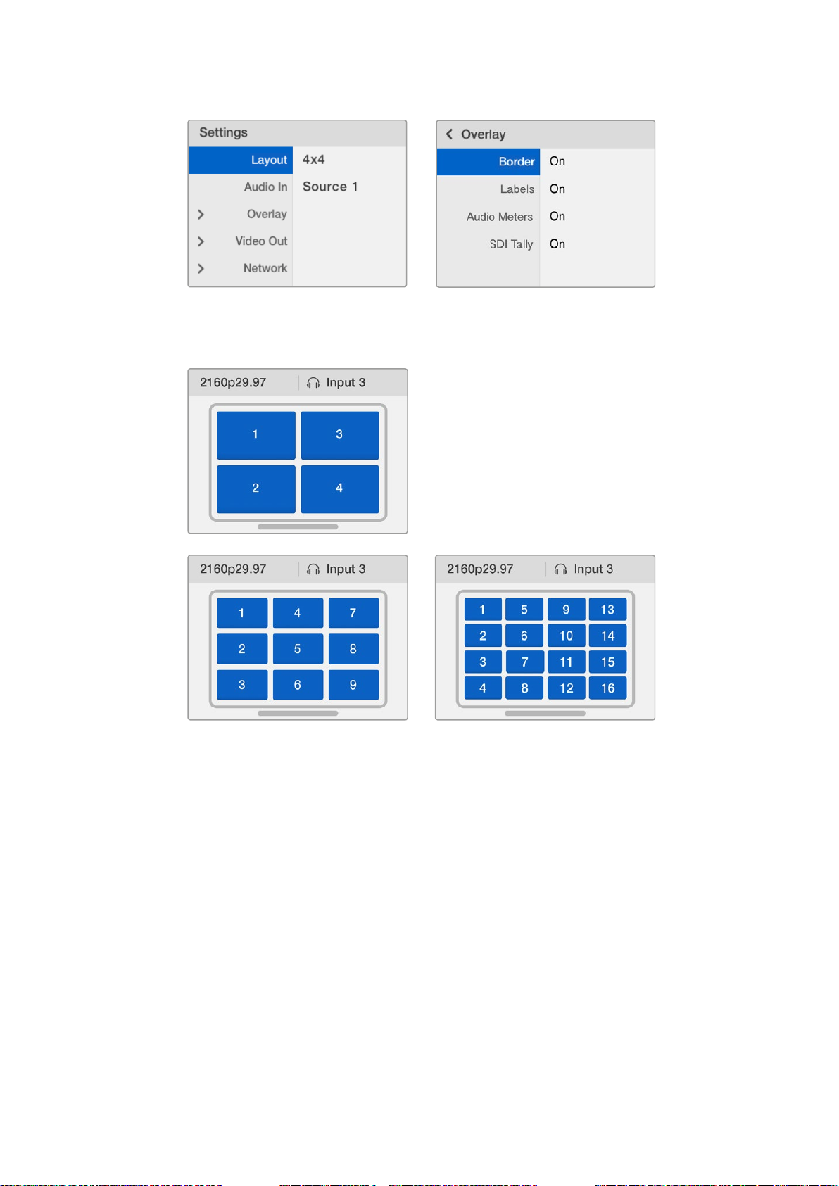
2 Layout is the first setting in the menu, so it is always highlighted when you first enter
the settings menu. Press the ‘set’ button to edit the setting.
66Getting Started
Page 7
3 Select 4x4 from the layout setting by turning the rotary knob on the front control panel.
LOOP OUT
IN
HDMI OUT 6G-SDI OUT HD-SDI OUT
16
SOLO
SET
SRC
VIEW
MENU
LOOP OUT
IN
HDMI OUT 6G-SDI OUT HD-SDI OUT
SRC
VIEW
MENU
LOOP OUT
IN
HDMI OUT 6G-SDI OUT HD-SDI OUT
4x4 lets you see all 16 source views on one screen. Whenever a setting changes, you’ll
notice the ‘set’ button and the ‘menu’ button will start flashing. This means a setting has
changed and you can either confirm the setting change by pressing the ‘set’ button, or
cancel by pressing the ‘menu’ button.
4 Press the set button to confirm your setting.
You can also set the layout using the Blackmagic MultiView 16 setup software using the
configure control panel.
1
4
7
10
13
16
SRC
2
5
8
11
14
SOLO
VIEW
3
6
9
12
15
SET
MENU
To set your Blackmagic MultiView 16’s view layout, press ‘menu’, select your layout
using the rotary knob, then press ‘set’. 4x4 lets you see all 16 views on one monitor.
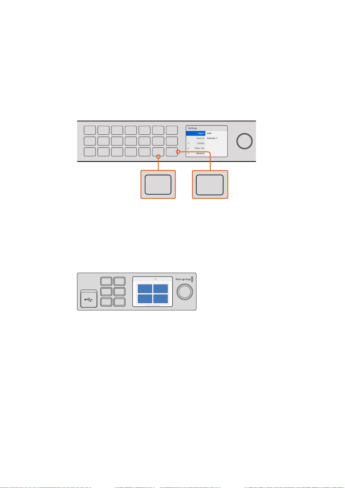
Setting your layout on Blackmagic MultiView 4
The default view on your Blackmagic Multiview 4 is the 2x2 layout. To change the layout on
your Blackmagic MultiView 4 to ‘solo’, use the control button marked as ‘1’ on your Teranex Mini
Smart Panel and press button ‘2’ to change it back to 2x2 display mode.
You can also set the layout using the ‘configure’ settings in the setup software.
1 MENU
2 VIDEO
SET AUDIO
To set your Blackmagic MultiView 4’s view layout, press ‘1’ for solo or press ‘2’ for 2x2 mode.
Connecting to a Network
Your Blackmagic MultiView supports the Blackmagic Videohub Ethernet Protocol so if your
unit is installed in a rack with limited access, you can easily control it remotely using a
Blackmagic Videohub control panel, such as Blackmagic Smart Control and Master Control.
Onceconnected to your network via Ethernet, your Blackmagic MultiView will be visible to
other computers and Videohub panels connected to the network. These devices can then
control the unit remotely.
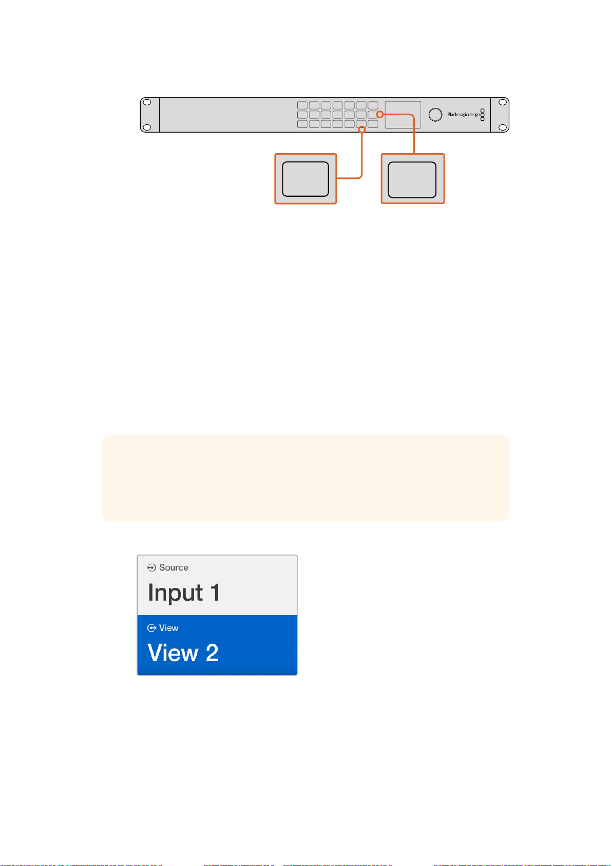
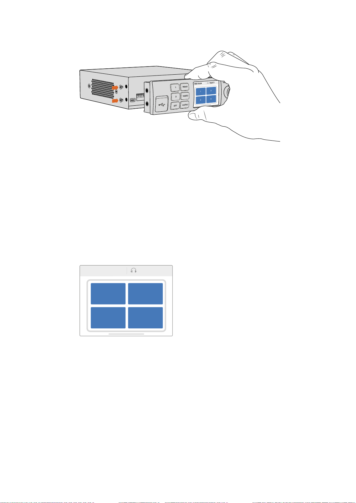
2160p 29.97 Input 3
1 3
2 4
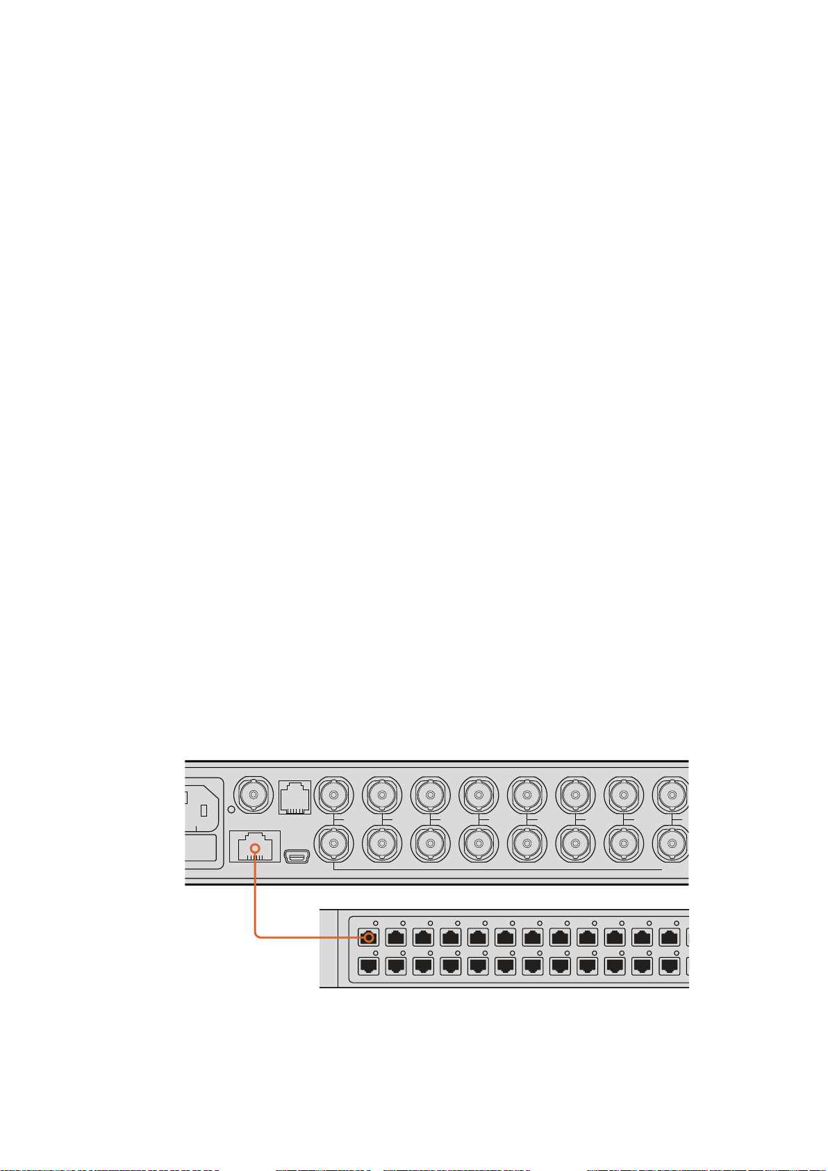
To connect Blackmagic MultiView to your network:
1 Power your Blackmagic MultiView
2 Use a standard RJ45 Ethernet cable to connect your Blackmagic MultiView to a
network or computer.
77Getting Started
Page 8
Once you have connected to a network, you’ll need to make sure your Blackmagic MultiView’s
IP address is different to the other equipment on your network. On Blackmagic MultiView 16
and when using MultiView 4 with a Teranex Mini Smart Panel installed, you can change the
network settings via the control panel’s LCD menu. You can also plug your Blackmagic
MultiView into a computer via USB and change network settings using Blackmagic MultiView
Setup. For more information on changing network settings refer to the ‘changing settings’
section in this manual.
Connecting Serial Control
Third party router controllers can control Blackmagic MultiView 16 using the RS-422 serial
connection. For more information on serial control, see the section ‘changing settings using
Blackmagic MultiView Setup’ in this manual.
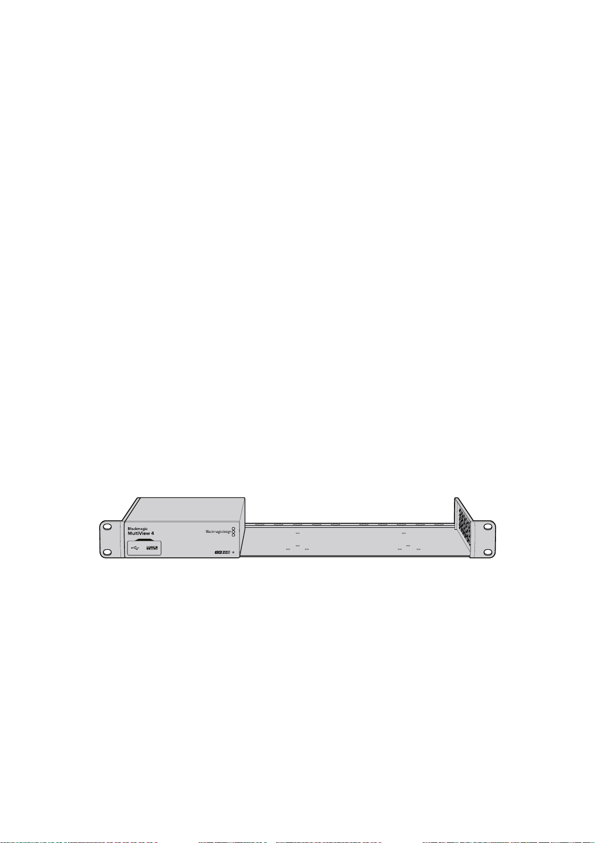
Rack Installation
Blackmagic MultiView 16 is 1 rack unit high so fits perfectly into any broadcast rack or road case.
Blackmagic MultiView 4 is much smaller and can be used in mobile productions where you may
not be using a broadcast rack. However, even though your MultiView 4 is designed to be small
and portable, you can still use it in a rack environment. The Blackmagic Teranex Mini Rack Shelf
is designed to let you mount up to three units side by side in a 1 rack unit space so you can
easily connect them to each other and build as many source views as you need.
Installing Blackmagic MultiView 4 into a Teranex Mini Rack Shelf is as easy as removing the
unit’s rubber feet, if installed, and screwing the unit into the base of the shelf using the
mounting holes on the bottom. The Teranex Mini Rack Shelf ships with two original blank panels
which you can use to cover gaps if you don’t need to install additional MultiView 4’s.
For more information check the Blackmagic Design website at www.blackmagicdesign.com
When installing your MultiView 4 in the rack shelf, ensure the rack shelf is mounted in the rack
by service personnel as the electrical rating on the underside of the unit will be covered. When
installed in the rack shelf, all connectors are accessed from the rear of the unit as normal.
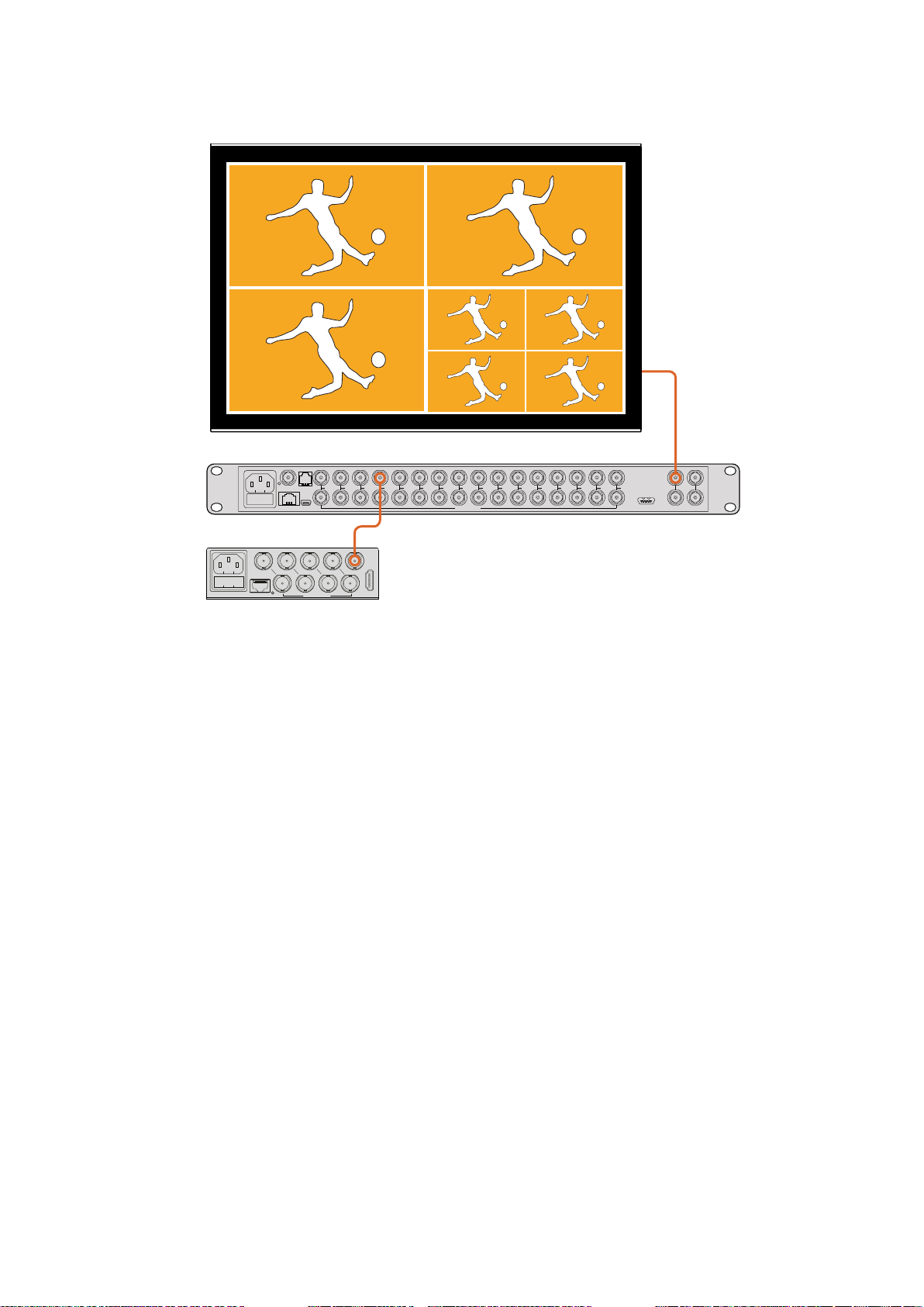
Using Multiple MultiViews
You can use multiple BlackMagic MultiViews in combination to create custom monitoring
setups. This is helpful if you need to add more view sources to your multi view output.
Simplyplug the output from one MultiView into the input of another to add more source views
to your multi view output. It is highly recommend that the upstream multi view output is
connected to an Ultra HD monitor for maximum clarity.
88Getting Started
Page 9
MultiView 4
Blackmagic
1 2 3 4 5 6 7 8 9 10 11 12 13 14 15 16
REF IN
RS-422
CNTRL
ETHERNET SD/HD/3G/6G-SDI IN
USB
HD
UHD
OUT
4
2
31
ETHERNET
SD/HD/3G/6G-SDI IN
HDMI OUT
LOOP OUT
IN
HDMI OUT 6G-SDI OUT HD-SDI OUT
By routing the output of one MultiView into the input of another,
you can add more views to your multi view layout.
That’s all there is to getting started. Keep reading the next sections of the manual to find
moreinformation about how to get the most from your Blackmagic MultiView, such as changing
settings, naming your views and more.
Changing Settings
There are several ways you can change settings on your Blackmagic MultiView.
Front Control Panel - Blackmagic MultiView 16 has a built in control panel and LCD so
you can easily change settings from the front of the unit.
Switches - The switches on Blackmagic MultiView 4’s front panel let you change
settings instantly using the tip of a pen. Access the switches by opening the rubber dust
cover on the front panel. A switch settings legend is printed on the base of the unit so
you can easily see the settings for each switch.
Teranex Mini Smart Panel - You can replace the original front panel of Blackmagic
MultiVIew 4 with an optional Teranex Mini Smart Panel so you can use the built in
control buttons, rotary knob and LCD. This functions in a very similar way to the front
control panel of Blackmagic MultiView 16 and gives you easy and intuitive local control.
Blackmagic MultiView Setup - The setup software lets you change settings via USB
or Ethernet using your computer. Refer to the ‘Blackmagic MultiView Setup’ section for
more information.
Videohub Control software - When your Blackmagic MultiView is connected to a
network, you can use Blackmagic Videohub Control software to route sources, change
views, and select the audio input source. Refer to the ‘Using Videohub Software
Control’ section for more information.
99Changing Settings
Page 10
Blackmagic MultiView 16’s Front Control Panel
ETHERNET SD/HD/3G/6G-SDI IN
REF IN
LOOP OUT
IN
HDMI OUT 6G-SDI OUT HD-SDI OUT
RS-422
CNTRL
USB
1 2 3 4 5 6 7 8 9 10 11 12 13 14 15 16
1
2
3
4
5
6
7
8
9
10
11
12
13
14
15
16
SOLO
SET
SRC
VIEW
MENU
LOOP OUT
IN
HDMI OUT 6G-SDI OUT HD-SDI OUT
Blackmagic MultiView 16’s front control panel makes it very easy to change any of the settings.
When first powering your Blackmagic MultiView 16 you’ll see the ‘home’ screen displayed on
the built in LCD. The home screen is the default display showing a convenient overview of
settings, such as:
Multi view output frame rate - Located in the upper left corner, this displays the
selected frame rate for your Ultra HD SDI multi view output.
Audio input - This information is located next to the multi view output frame rate and
displays which SDI input is being used for embedded audio in the HDMI and SDI multi
view output signal.
Multi view layout - This displays your selected multi view layout.
The ‘home’ screen is the default display on Blackmagic
MultiView 16’s control panel LCD. This screen displays
your selected multi view layout, the frame rate for
the multi view SDI output, and the selected SDI input
used to embed audio into the multi view output.
Control Panel Buttons
The illuminated buttons on Blackmagic MultiView 16’s control panel make it very easy to adjust
settings and set your sources and views.
1
4
7
10
13
16
2
5
8
Blackmagic MultiView 16
3
11
6
9
12
Blackmagic MultiView 16’s control panel buttons let you easily
change settings and switch views from the front of the unit.
14
15
SRC
SOLO
VIEW
SET
MENU
Solo Button
You can monitor a view in full screen by pressing the ‘solo’ button. Now press any view button on
the control panel to monitor that view in full screen mode. Press solo again to return to the multi
view layout.
1010Changing Settings
Page 11
The solo feature lets you monitor a
view in full screen mode.
Menu Button
Press the ‘menu’ button to open the settings screen. Change a setting using the rotary knob
and set button, then press the menu button again to return to the ‘home’ screen.
Set Button
Press the ‘set’ button to select a setting to adjust. After changing a setting, press the set button
again to confirm the change.
Source and View buttons
These buttons let you select which input source you want to display in a desired view. When
navigating settings menus, the source and view buttons can also be used to move up and down
through setting options.
Rotary Knob
Use the rotary knob to scroll through settings, or to select menu items on the settings screen.
Ifyou’re unhappy with a selection, you can return to a previously selected setting by pressing
the rotary knob.
Turn the rotary knob clockwise or counter clockwise to select between two options in a menu.
Settings can also be turned on or off by pressing the knob.
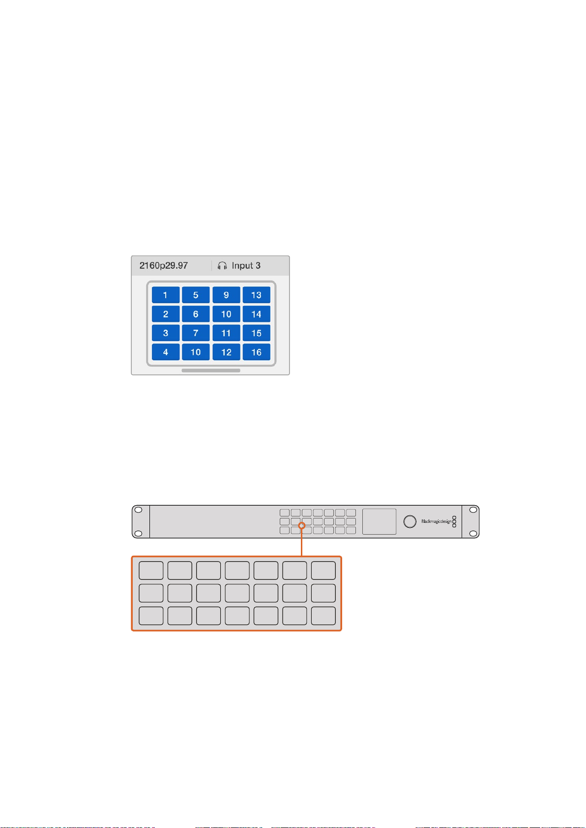
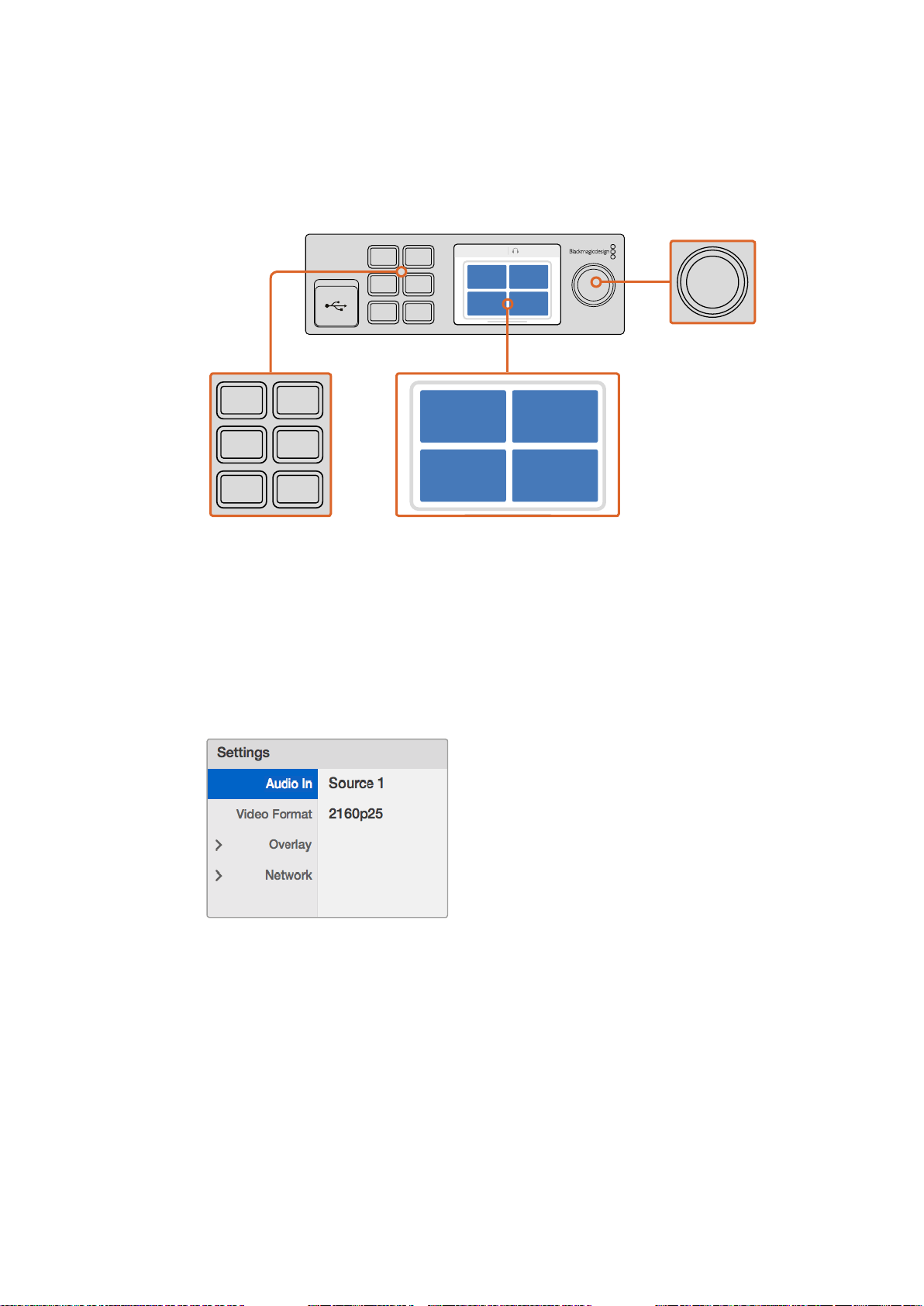
Setting your Sources and Views on Blackmagic MultiView 16
One of the key features of Blackmagic MultiView 16 is the ability to assign your connected
SDIsources to different views. By adjusting these settings you can easily change the
arrangement of your views. For example, you may want SDI input 5 to appear on view 1.
To set which source appears on a desired view:
1 Press the ‘view’ button on the front control panel to open the view selection screen.
The view selection will be highlighted with a blue background.
2 Press a numbered view button to select your desired view. Alternatively, you can
use the rotary knob to scroll through the views. Confirm your setting by pressing the
‘set’ button.
3 Press the ‘src’ button. The source section of the LCD will be highlighted.
4 Press a numbered view button on the control panel to select your desired input.
Alternatively, you can use the rotary knob to scroll through your inputs on the LCD.
5 Press the ‘set’ button to confirm your setting.
1111Changing Settings
Page 12
1
ETHERNET SD/HD/3G/6G-SDI IN
REF IN
LOOP OUT
IN
HDMI OUT 6G-SDI OUT HD-SDI OUT
RS-422
CNTRL
USB
1 2 3 4 5 6 7 8 9 10 11 12 13 14 15 16
16
SOLO
SET
SRC
VIEW
MENU
LOOP OUT
IN
HDMI OUT 6G-SDI OUT HD-SDI OUT
SRC
VIEW
LOOP OUT
IN
HDMI OUT 6G-SDI OUT HD-SDI OUT
4
7
10
13
16
SRC
14
SOLO
VIEW
15
SET
MENU
Blackmagic MultiView 16
2
5
8
3
11
6
9
12
To set a source to a view, press the ‘view’ button
toenter the view setting, makeyour selection, then
press the ‘set’ button to confirm your setting.
Setting your Layout on Blackmagic MultiView 16
On Blackmagic MultiView 16, you can select the number of views that appear on your multi view
output. For example, if you have 4 inputs connected, you can easily select the 2x2 layout which
displays four views in a vertical x horizontal grid. For optimum monitoring of your inputs, select
the view layout to suit the number of inputs connected.
There are four multi view layouts you can choose from:
2x2 displays 4 views. If you have an Ultra HD monitor connected, each source will be
displayed in native HD resolution.
3x3 displays 9 views.
4x4 displays all 16 views.
TIP You can also monitor a view in full screen mode by pressing the ‘solo’
button on Blackmagic MultiView 16’s control panel, then selecting a view
button. On Blackmagic MultiView 4, press the solo button marked ‘1’ on the
Teranex Mini Smart Panel.
Select your view you wish to assign a source
to using the rotary knob or view buttons.
1212Changing Settings
Page 13
Highlight the menu item you with to adjust and
press “set” to open its settings.
You can choose from 3 different multi view layouts to
best suit the number of inputs you haveconnected.
Audio In
This setting is used to select the SDI input from which audio will be taken and embedded into
the multi view outputs.
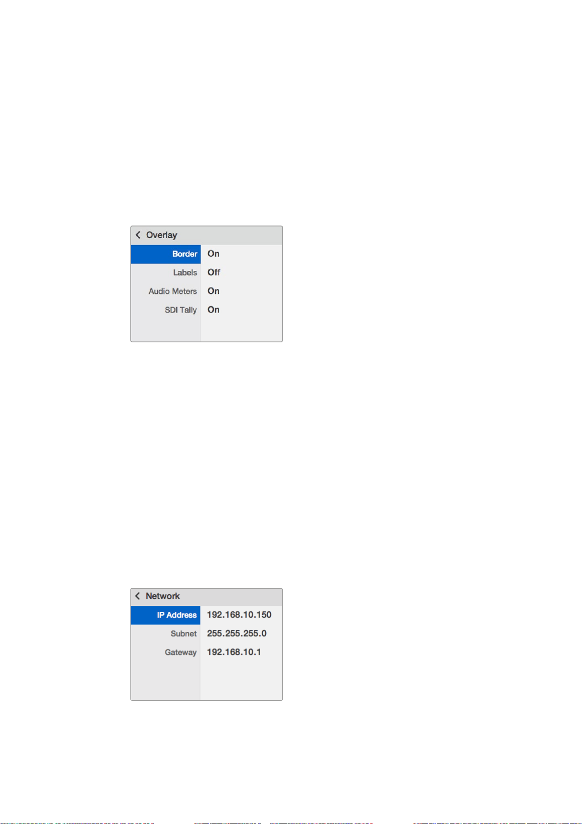
Overlay
This submenu lets you change the appearance of your multi view by turning overlay features
on or off.
Overlay features are:
Borders - Lets you separate each view in a grid like pattern.
Labels - Makes ‘view’ labels visible or hidden. Labels can be changed using
Blackmagic MultiView Setup.
Audio Meters - Turns audio VU meters on or off for all the views. The first 2 channels
embedded in each SDI signal are displayed in each view, which means you can monitor
audio levels together with the picture.
1313Changing Settings
Page 14
SDI Tally - When Blackmagic MultiView 16 has an ATEM switcher’s program SDI output
SD/HD/3G/6G-SDI IN
8 9 10 11 12 13 14 15 16
connected to input 16, you can view tally borders around a view when its source is
switched to air. You can turn this feature on or off using the SDI tally overlay setting.
For tally to work properly, make sure you connect your Blackmagic MultiView 16’s inputs so they
match the input numbers on your ATEM switcher or tally may be displayed on the wrong view.
Video Out
The ‘video out’ settings let you control output options on your Blackmagic MultiView 16.
Video Format - Use this setting to change your Ultra HD multi view output frame rate to
2160p29.97 or 2160p25. The HD multi view output frame rate will conform to the Ultra
HD output. Press the rotary knob if you want to cancel the setting change, or return to
the previous menu.
HD Output - Select interlaced or progressive for the HD multi view output. If
2160p29.97 is the selected video format the HD output can be either 1080p29.97 or
1080i59.94. Similarly when 2160p25 is selected the HD output can be either 1080p25
or 1080i50.
Network
The ‘network’ settings let you set the IP, Subnet and Gateway addresses for your Blackmagic
MultiView 16 when connecting to a network.
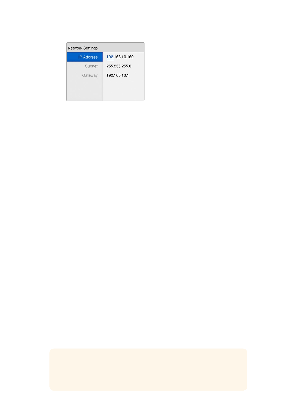
To set your Blackmagic MultiView 16’s IP address:
1 Press the ‘menu’ button on the front control panel and use the rotary knob to highlight
the ‘networking’ tab on the LCD menu.
2 Press the ‘set’ button to enter the network settings screen.
3 Turn the rotary knob to select the “IP address” tab.
4 Press the ‘set’ button to highlight the first field of the IP address. Use the rotary knob to
change values.
5 Press ‘set’ to confirm the first field, then repeat the above step for the next three fields.
If you need to assign the subnet and gateway address, they can be set using the
same method.
6 Press the menu button twice to return to the home screen.
REF IN
ETHERNET
RS-422
CNTRL
USB
1 2 3 4 5 6 7
Connecting Blackmagic MultiView 16
to an Ethernetnetwork will allow you to
control the unitfromanother location.
1414Changing Settings
Page 15
Use the rotary knob or the view buttons on
Blackmagic MultiView 16’s control panel to
assign values to your network settings.
Changing Settings using
TeranexMiniSmart Panel
The Teranex Mini Smart Panel mounts to the front of your Blackmagic MultiView 4 and replaces
the original basic panel. You get fast access to your settings using buttons, a rotary knob and
built in LCD.
Installing Teranex Mini Smart Panel
Installing your optional Smart Panel is easy and because the panels are hot swappable you
don’t even need to turn off your Blackmagic MultiView 4 when installing it.
1 Remove the two M3 screws on each side of your Blackmagic MultiView 4’s basic front
panel using a Pozidriv 2 screwdriver and gently pull the panel away from the front
of the unit.
2 Remove and retain the light tube connecting the LED to the indicator at the bottom of
the basic panel. This tube is necessary to illuminate the built in status indicator when
the Smart Panel is not installed.
3 Align the connector on the rear of the Smart Panel with the adjoining connector on the
face of your Blackmagic MultiView 4 and gently push the Smart Panel towards the unit
until the connectors are firmly seated. The Smart Panel should make a firm connection
and fit neatly inside the face of your Blackmagic MultiView 4.
4 Re-insert the M3 screws from the original panel.
If your Blackmagic MultiView 4 is installed in a Teranex Mini Rack Shelf, you will need to remove
the unit from the rack shelf to access the front panel screws.
See the ‘Rack Installation’ section for more information.
Your Blackmagic MultiView 4’s USB port is still accessible with the Smart Panel attached.
Toaccess the port, simply open the rubber USB dust cover. With the Smart Panel installed, the
front panel small switches are covered up and no longer used and this is because all the switch
settings are now in the menu on the Teranex Smart Panel and can be set using the LCD.
TIP The original basic panel is very strong, so if you need to mount
yourBlackmagic MultiView 4 in the back of a rack system or in areas where
there are lots of cables or activity, you can always reinstall the original
basic panel.
1515Changing Settings using TeranexMiniSmart Panel
Page 16
When installing the Teranex Mini Smart Panel to your Blackmagic MultiView 4, holding the panel
1
2
SET
VIDEO
MENU
AUDIO
2160p 29.97 Input 3
1 3
2 4
with your fingers and thumb aligned with the panel’s rear connector will help guide it into place.
Teranex Mini Smart Panel Features
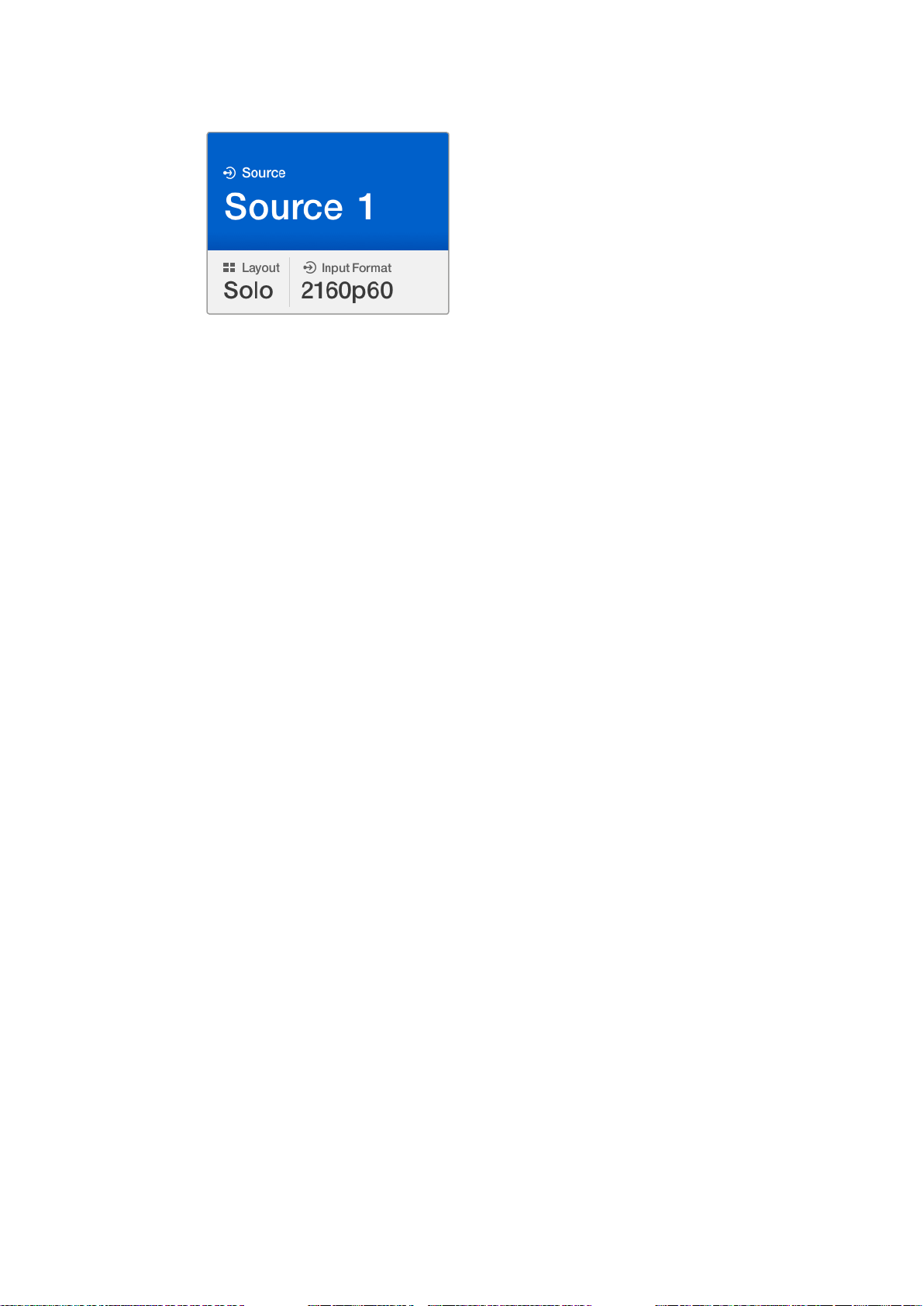
The features of the Smart Panel are similar to the MultiView 16’s built in control panel. The home
screen is the first feature you’ll see on the LCD and is the default display showing a convenient
overview of settings, such as:
Multi view output frame rate - Located in the upper left corner, this displays the
selected frame rate for your Ultra HD SDI multi view output.
Audio input - This information is located next to the multi view output frame rate and
displays which SDI input is being used for embedded audio in the HDMI and SDI multi
view output signal.
Multi view layout - This displays the 2x2 multi view layout.
Control Buttons and Rotary Knob
Your Teranex Mini Smart Panel has a set of buttons and a rotary knob that are used to navigate
your Blackmagic MultiView 4’s settings menu.
1 and 2 buttons - Press these buttons to increase or decrease numeric setting values,
Set - After changing a setting using the 1 and 2 buttons, press the ‘set’ button to
Menu - Press to enter the settings menu for your Blackmagic MultiView 4. You can
The ‘home’ screen is the default display
on TeranexMini Smart Panel’s LCD.
or to move up or down through menu settings.
confirm your setting.
also press the menu button to step back through menu items all the way to the
home screen.
1616Changing Settings using TeranexMiniSmart Panel
Page 17
Video and Audio Buttons - These buttons are specific to Teranex Mini converters and
2160p 29.97 Input 3
1 3
2 4
1 MENU
2 VIDEO
SET AUDIO
2160p 29.97 Input 3
1 3
2 4
are not used with Blackmagic MultiView 4.
Rotary Knob - Turn the rotary knob clockwise or counter clockwise to navigate through
the menu settings and adjust numeric setting values.
1 MENU
2 VIDEO
SET AUDIO
2160p 29.97 Input 3
1 3
2 4
Rotary Knob
Control Buttons
Video monitor - displays the home screen
and is used when changing settings.
Changing Settings using Teranex Mini Smart Panel
Changing settings using the Teranex Mini Smart Panel is more convenient and you can
immediately confirm your settings visually on the LCD.
To enter your Blackmagic MultiView 4’s setup menu, press the ‘menu’ soft button on the
Teranex Mini Smart Panel. Here you can access the following settings.
Audio In
This setting is used to select the SDI input from which audio will be taken and embedded into
the multi view outputs.
Video Format
Your Blackmagic MultiView 4 can be set to Ultra HD or HD output at either 29.97 or 25 frames
per second. Use this setting to cycle through the available resolution and frame rate options.
Highlight the menu item you wish to adjust
and press “set” to select it. Scroll through
the settings using the rotary knob.
1717Changing Settings using TeranexMiniSmart Panel
Page 18
Overlay
The overlay submenu lets you set the appearance of overlay features on or off.
Overlay features are:
Borders: Lets you separate each view in a grid like pattern.
Labels: Makes ‘view’ labels visible or hidden. Labels can be changed using Blackmagic
MultiView Setup.
Audio Meters: Turns audio VU meters on or off for all the views. The first 2 channels
embedded in each SDI signal are displayed in each view, which means you can monitor
audio levels together with the picture.
Network
The ‘network’ settings let you set the IP, Subnet and Gateway addresses for your Blackmagic
MultiView 4 when connecting to a network.
To set your Blackmagic MultiView 4’s IP address:
1 Press the ‘menu’ button on the front control panel and use the rotary knob to highlight
the ‘networking’ tab on the LCD menu.
2 Press the ‘set’ button to enter the network settings screen.
3 Turn the rotary knob to select the “IP address” tab.
4 Press the ‘set’ button to highlight the first field of the IP address. Use the rotary knob to
change values.
5 Press ‘set’ to confirm the first field, then repeat the above step for the next three fields.
If you need to assign the subnet and gateway address, they can be set using the
same method.
6 Press the menu button twice to return to the home screen.
Use the rotary knob or the “1” and “2” buttons
on Teranex Mini Smart Panel to assign values to
yourBlackmagic MultiView 4 network settings.
1818Changing Settings using TeranexMiniSmart Panel
Page 19
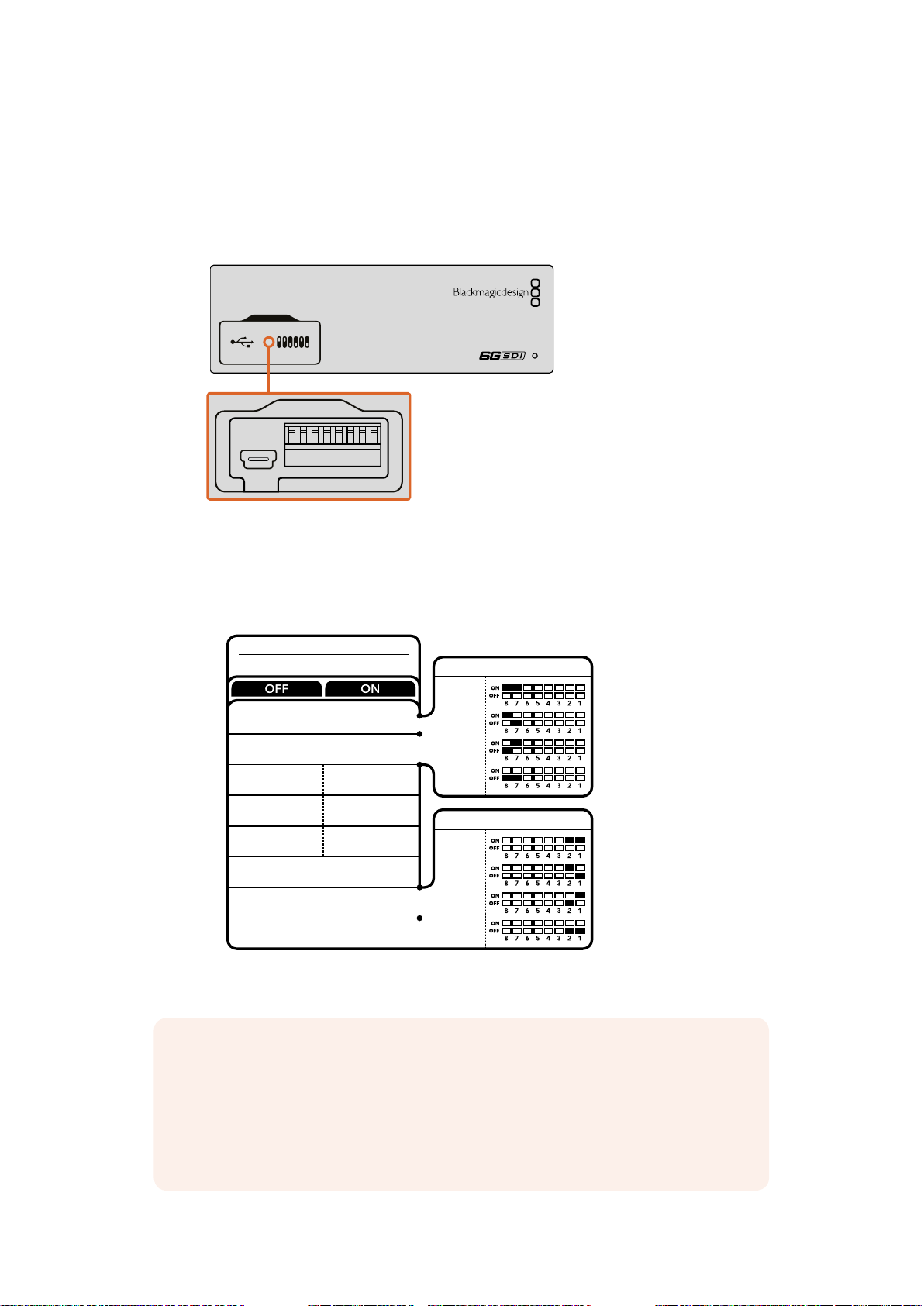
Changing Settings using Switches
1ON2 3 4 5 6 7 8
On the front panel of your Blackmagic MultiView 4 you’ll see a rubber dust cover which protects
a set of small switches used for changing settings. The ‘on/off’ switches are used to configure
internal settings and you can easily change them using the tip of a pen.
Blackmagic
MultiView 4
Change settings by adjusting the switches with a pen.
You’ll find a switch settings diagram printed on the base of your Blackmagic MultiView 4.
Ensureyour switch settings correspond to the legend by observing the switch numbers
from8to 1, left to right.
Blackmagic
MultiView 4
8
7
6
5
4
3
2
1
Your Blackmagic MultiView 4’s switches provide the following settings:
AUDIO SELECTION BIT 1
AUDIO SELECTION BIT 0
LABELS OFF
AUDIO METERS
OFF
BORDER OFF BORDER ON
SDI OUTPUT BIT 1
SDI OUTPUT BIT 0
LABELS ON
AUDIO METERS
ON
AUDIO SOURCE
INPUT 1
INPUT 2
INPUT 3
INPUT 4
SDI OUTPUT
2160p29.97
2160p25
1080i59.94
1080i50
NOTE When using the optional Teranex Mini Smart Panel, the switch settings
will be overridden by the Smart Panel settings. Your Blackmagic MultiView 4 will
retain its last settings whether applied via switch, Smart Panel or Blackmagic
MultiView Setup software. If reverting to switch control after removing the Smart
Panel or updating your Blackmagic MultiView 4’s settings via software, you may
need to toggle individual switches for new settings to take effect.
1919Changing Settings using Switches
Page 20
TIP Even though switch settings are printed on the base of your Blackmagic
MultiView 4, new features in later updates can add new settings so it’s worth
checking the latest version of this manual for the most up to date information.
You can download the latest version from the Blackmagic Design support
center at www.blackmagicdesign.com/support
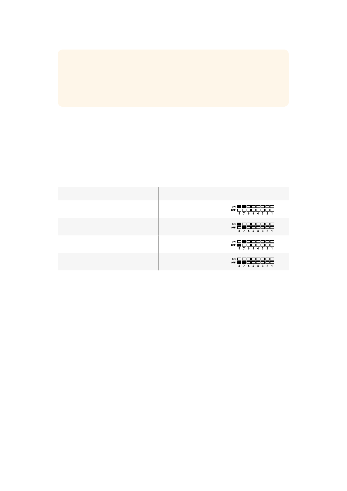
Switch Settings
Switch 8 and 7 - Audio Selection
Switches 8 and 7 are represented as bits 1 and 0 respectively. This means that by setting
various on/off combinations of switches 8 and 7 you can select which SDI input is being used
for embedded audio in the HDMI and SDI multi view output signal.
Audio Selection Table
Audio Source Switch 8 Switch 7 Switch Diagram
Input 1 ON ON
Input 2 ON OFF
Input 3 OFF ON
Input 4 OFF OFF
Switch 6 - Labels
Set switch 6 to ‘on’ to display labels for each window in your multi view output signal. These
labels can be set using Blackmagic MultiView setup as detailed later in this manual. Set switch 6
to ‘off’ to hide labels.
Switch 5 - Audio Meters
Set switch 5 to ‘on’ to display audio meters for each window in your multi view output signal. Set
switch 5 to ‘off’ to hide audio meters.
Switch 4 - Borders
Set switch 4 to ‘on’ to display borders between each MultiView window. Set switch 4 to ‘off’ to
hide borders.
Switch 2 and 1
Switches 2 and 1 are represented as bits 1 and 0 respectively. This means that by setting various
on/off combinations of switches 2 and 1 you can select the output format of your MultiView 4’s
SDI signal.
2020Changing Settings using Switches
Page 21

SDI Output Selection Table
SDI Output Switch 2 Switch 1 Switch Diagram
2160p29.97 ON ON
2160p25 ON OFF
1080i59.94 OFF ON
1080i50 OFF OFF
Using Blackmagic MultiView Setup
Blackmagic MultiView Setup lets you easily configure your Blackmagic MultiView from any Mac
or Windows PC, as well as update the unit’s internal software. The utility is intuitive and easy to
use, plus if you have Blackmagic MultiView 4 connected to a network, you can even change
settings via Ethernet so you don’t have to plug in via USB.
Installing Blackmagic MultiView Setup
Blackmagic MultiView Setup runs on 64-bit versions of Windows and on the latest Yosemite and
El Capitan versions of Mac OS X.
Windows installation
1 Double click the installer file from the supplied media or from your downloads folder if
you downloaded the software from the Blackmagic Design website.
2 Follow the install prompts and accept the terms in the license agreement and Windows
will automatically install the software.
Click the Windows ‘start’ button and then All Programs>Blackmagic Design>MultiView. The
multi view folder contains the Blackmagic MultiView setup application.
Mac OS X installation
1 Double click the installer file from the supplied media or from your downloads folder if
you downloaded the software from the Blackmagic Design website.
2 Follow the install prompts and Mac OS X will automatically install the software.
A folder called “Blackmagic MultiView” will be created within your applications folder,
containing the Blackmagic MultiView Setup application.
2121Using Blackmagic MultiView Setup
Page 22
To install the Blackmagic MultiView setup,
double click the installer and follow the prompts.
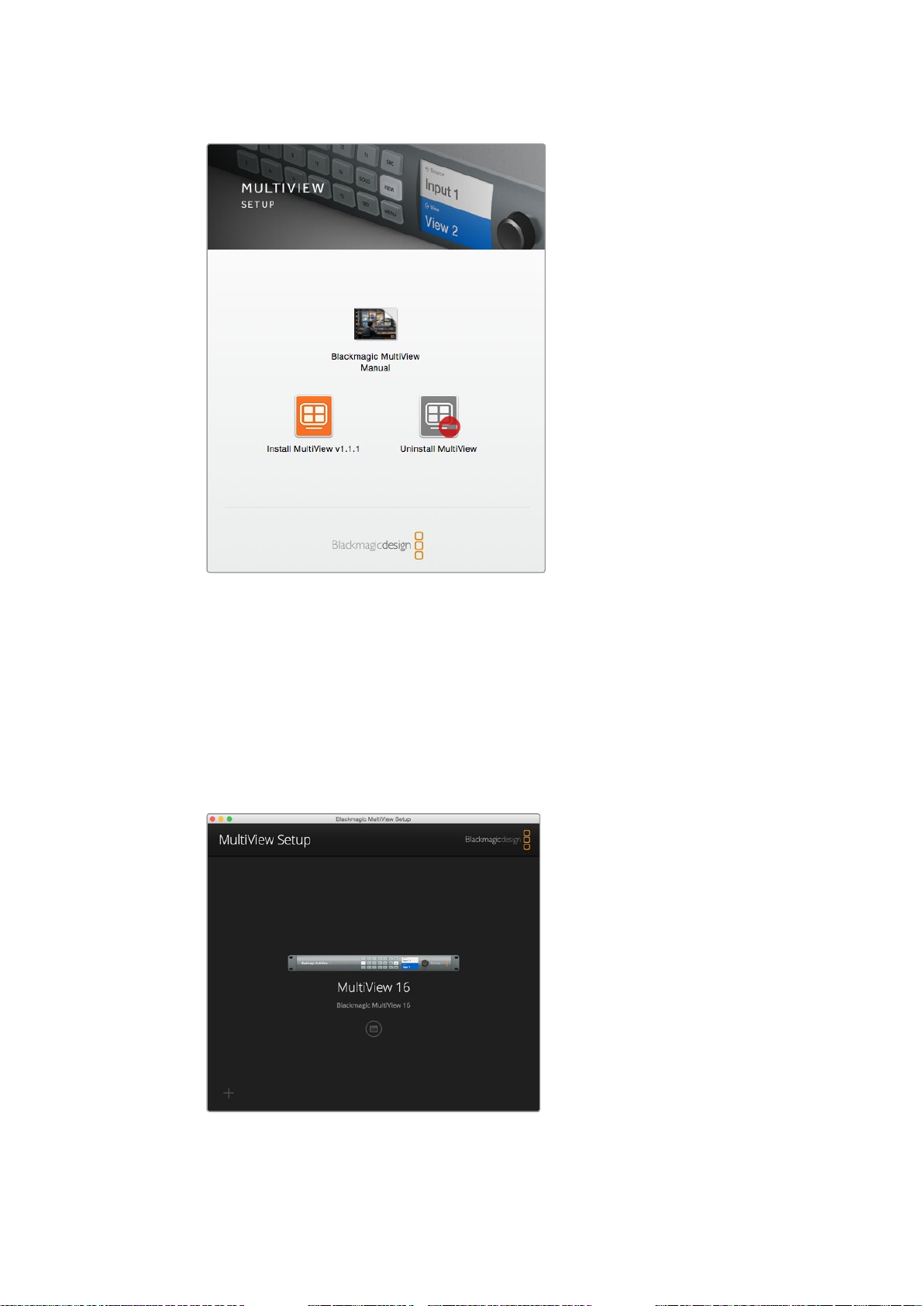
Blackmagic MultiView Setup Home Page
The first thing you will see after launching Blackmagic MultiView Setup is the software home
page. If you have multiple Blackmagic MultiView connected to your network, you can select
them by clicking on the arrows on the left and right side of the home page.
To access settings for your Blackmagic MultiView, click on the circular settings icon underneath
the product image, or you can click on the image itself.
Blackmagic MultiView Setup lets you change your
BlackmagicMultiView settings from a computer
when connected via Ethernet or USB.
2222Using Blackmagic MultiView Setup
Page 23
Changing Settings using Blackmagic MultiView Setup
Click on the settings icon to open the setup settings for your Blackmagic MultiView. In the
settings window you will see three tabs named ‘sources’, ‘views’ and ‘configure’. On Blackmagic
MultiView 4, the ‘views’ setting is not required as its views are not adjustable via the Videohub
Control software.
TIP Make sure your network settings on the unit matches that on your
computer for sources to be displayed.
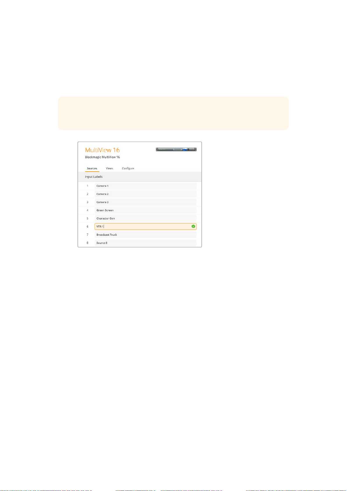
Use Blackmagic MultiView Setup to customize input labels so you
can quickly identify each source within the multi view layout.
Sources - Lets you customize your input labels. This changes how your sources are
labelled on your multi view display.
Views - This tab is only relevant when controlling Blackmagic MultiView 16 via
Videohub Control software. By changing the name of the views, you can make them
easier to identify within the destinations panel in the Videohub Control software.
Configure - The ‘configure’ tab gives you control over settings such as device name
customization, video output and overlay settings, plus network settings and serial
control adjustments.
Sources
Customizing Input Labels
Labeling your sources lets you quickly identify each source within the multi view layout. You can
also save and load label sets, so if you regularly use your Blackmagic MultiView for different
applications, you can quickly load labels without the need to re-enter them.
Labels are visible in the Videohub Control software and also to networked Videohub
control panels.
To customize your input labels:
1 Click on the ‘sources’ tab.
2 In the ‘input labels’ setting, click the text box for the input source name you want to
change and enter a new label name.
3 Click ‘save’ to confirm your setting.
2323Using Blackmagic MultiView Setup
Page 24
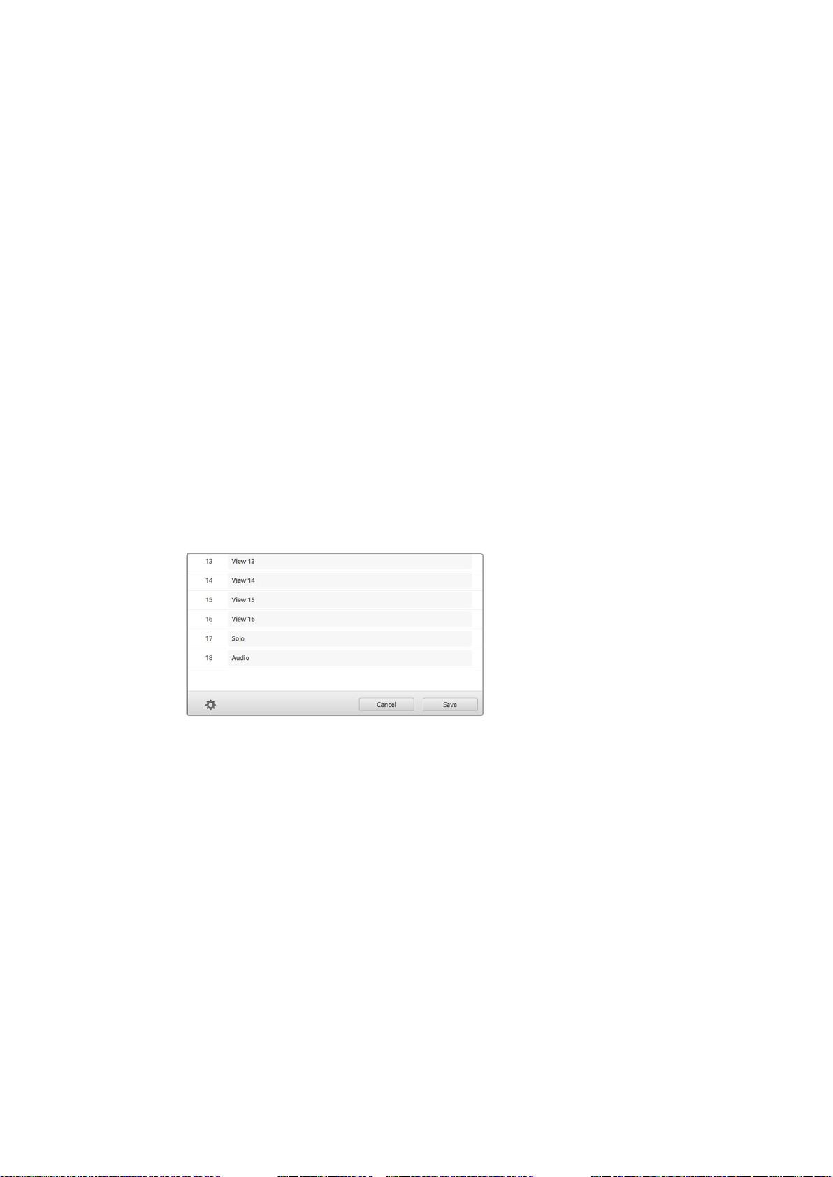
Views
Customizing View Labels
On Blackmagic MultiView 16, you can change the labels of the views so they are easier to
identify as destinations when controlling your MultiView 16 via Videohub Control software.
To customize the view labels:
1 Click on the ‘views’ tab.
2 In the ‘output labels’ setting, click the text box for the view you want to change and
enter a new label name.
3 Click ‘save’ to confirm your setting.
When the ‘view’ labels are at their default state, you willnotice output 17 is labelled ‘solo’ and
output 18 is labelled ‘audio’.
Output 17 lets you change the software label for the ‘solo’ setting which is controlled using your
Blackmagic MultiView 16’s front panel. This is beneficial when controlling your MultiView 16
using Blackmagic Videohub Control software. Customizing the ‘solo’ output label in Blackmagic
MultiView Setup lets you change how it appears in Blackmagic Videohub Control.
Output 18 relates to the ‘audio in’ setting in your Blackmagic MultiView 16’s LCD menu, which
routes the audio you wish to embed in your multi view output. Similar to the ‘solo’ output label,
you can change the view label so you can customize its appearance when controlling
Blackmagic MultiView 16 using Blackmagic Videohub Control.
The inclusion of the “solo” and “audio” output labels
let you change their names so you can customize
how they appear when controlling your Blackmagic
MultiView 16 using Blackmagic Videohub Control.
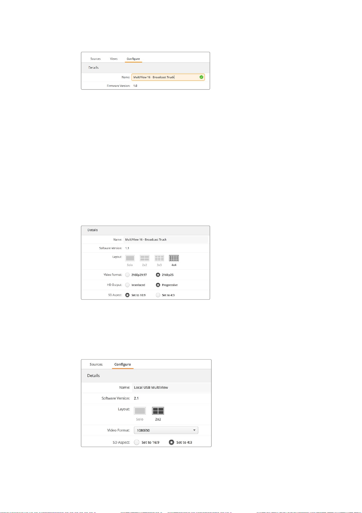
Configure
Naming your Blackmagic MultiView
The ‘configure’ tab is divided into three groups of settings including ‘details’, ‘overlay’ and
‘network settings.’ These differ slightly depending on whether you’re configuring Blackmagic
MultiView 16 or Blackmagic MultiView 4.
To name your Blackmagic MultiView so it’s easy to identify when used remotely:
1 Click on the ‘configure’ tab.
2 In the ‘details’ setting, click the ‘name’ text box and enter a new label for your
Blackmagic MultiView.
3 Click ‘save’.
2424Using Blackmagic MultiView Setup
Page 25
Use Blackmagic MultiView Setup to name your Blackmagic
MultiView 16 so it’s easy for network users to identify.
Changing the Multi View Layout
Similar to the ‘layout’ settings on Blackmagic MultiView 16’s control panel LCD menu, you can
also change the layout using the setup software. Choose the layout setting you wish to use by
clicking on the desired layout icon in the ‘details’ settings.
Video Format and HD Output
Video Format settings differ slightly between Blackmagic MultiView 16 and Blackmagic
MultiView 4.
Blackmagic MultiView 16 can output Ultra HD and HD videos simultaneously, so you can select
between Ultra HD video frame rates to set ‘video format’ and interlaced or progressive mode
for the ‘HD output’. The HD frame rate will automatically conform to your Ultra HD settings. For
example, if 2160p25 is selected, the HD output can be either 1080p25 or 1080i50.
The radio buttons in the ‘configure’ tab for
MultiView 16 are used to set the layout, video
format, HD output and SD aspect ratio.
On Blackmagic MultiView 4 you can choose whether to output Ultra HD or HD video via the SDI
output, as well as set the frame rate. These are consolidated into the ‘video format’ dropdown
menu, with no separate ‘HD output’ menu.
The ‘configure’ tab for Blackmagic MultiView 4
contains a dropdown list of video format options
that covers both resolution and frame rate.
2525Using Blackmagic MultiView Setup
Page 26
SD Aspect
If 4:3 SD video is connected to your Blackmagic MultiView, check the ‘set to 4:3’ checkbox. This
ensures your 4:3 video displays using the correct aspect ratio.
If 16:9 SD video is connected, check the ‘set to 16:9’ checkbox to display the image correctly
in its view.
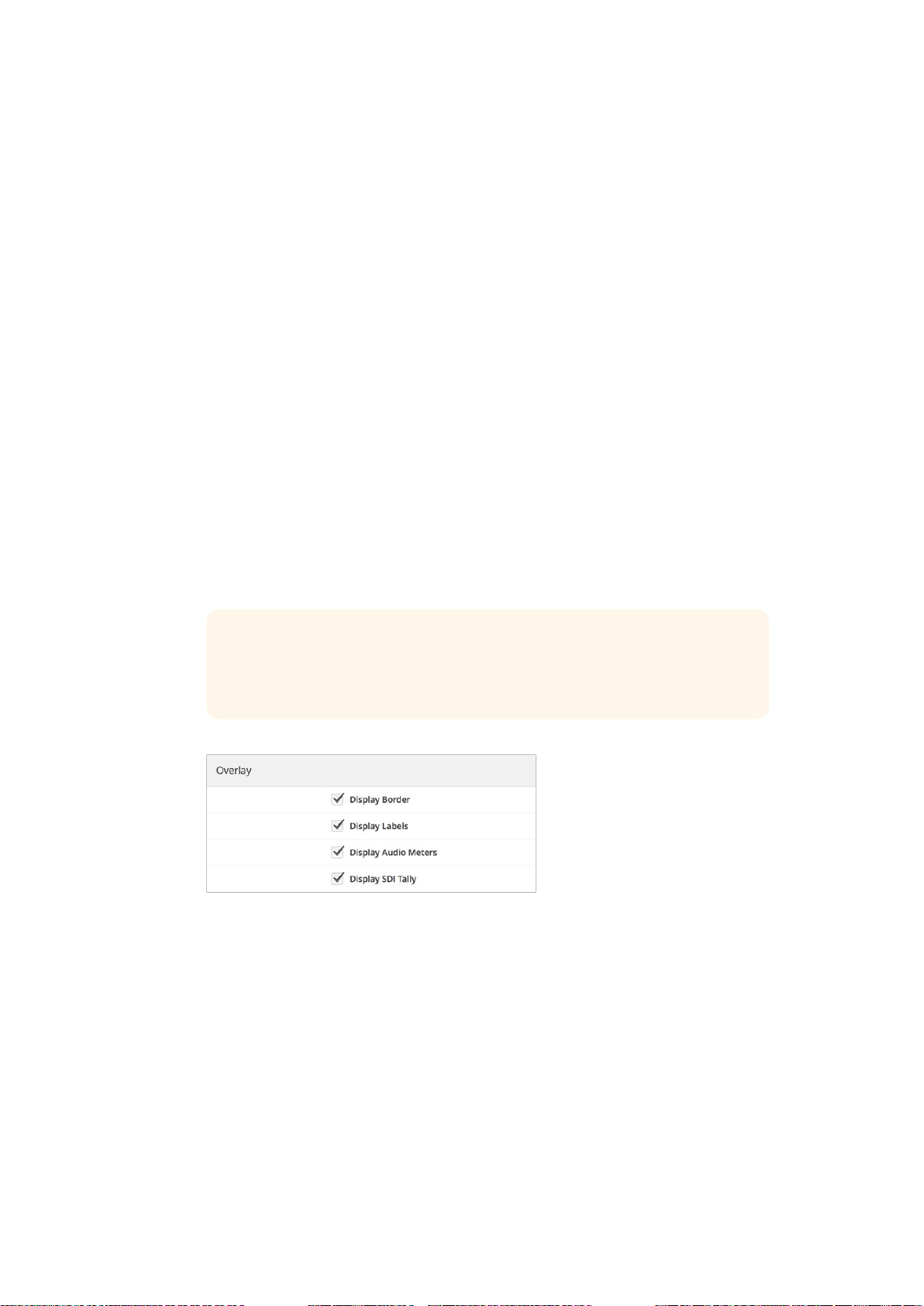
Overlay
Check the checkboxes in the ‘overlay’ settings to enable each feature on your
BlackmagicMultiView.
Overlay features are:
Borders: Lets you separate each view in a grid like pattern.
Labels: Makes ‘view’ labels visible or hidden. Labels can be changed using Blackmagic
MultiView Setup.
Audio Meters: Turns audio VU meters on or off for all the views. The first 2 channels
embedded in each SDI signal are displayed in each view, which means you can monitor
audio levels together with the picture.
SDI Tally: When your Blackmagic MultiView has an ATEM switcher’s program SDI
output connected to the last input, for example input 16 on Blackmagic MultiView
16, or input 4 on Blackmagic MultiView 4, you can view tally borders around a view
when its source is switched to air. You can turn this feature on or off using the tally
overlay setting.
TIP For tally to work properly, make sure you connect all your
Blackmagic MultiView inputs so they match the input numbers on your
ATEM switcher or tally may be displayed on the wrong view.
The overlay settings in the ‘configure’ tab lets youturn overlay
features on or off such as borders, ‘view’ labels, audio meters,
or even SDItally borders on your Blackmagic MultiView.
Network and Serial Control Settings
Network and serial control settings can be set using Blackmagic MultiView Setup when your
Blackmagic MultiView 16 is connected to your computer via USB. You can also change these
settings using the front control panel LCD menu. When configuring Blackmagic MultiView 4,
only network settings are available.
To change network settings, simply click in the text box and enter the values with your
keyboard, or check the desired checkbox.
2626Using Blackmagic MultiView Setup
Page 27
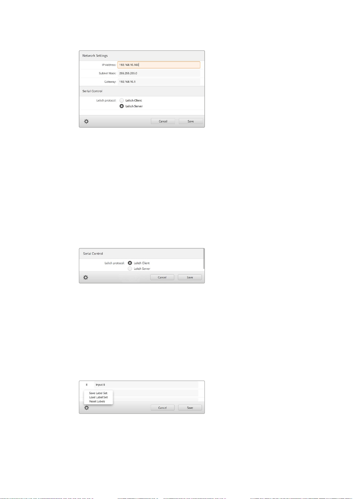
When connecting to a network you may need to change your
MultiView 16’s ‘network settings’ to suit. ‘Serial control’ settings lets
you set your MultiView 16 for Lietch client or server configuration
based on your RS-422 remote control setup requirements.
To set up serial control, connect Blackmagic MultiView 16 to your computer via USB and follow
the steps below:
1 Launch Blackmagic MultiView setup and select your Blackmagic MultiView 16 by
clicking on the product image or the settings icon below it.
2 Click on the ‘configure’ tab and set the “Leitch Protocol” switch to “Leitch Client” if your
Blackmagic MultiView16 is to act as a client of a connected control panel, or “Leitch
Server” if your unit is to be controlled from an automation system or third party router
control system.
3 Click on the ‘save’ tab to confirm your setting.
Select either ‘client’ or ‘server’ when using RS-422 serial control.
Saving and Loading Label Sets
If you are regularly using a set of labels for a recurring project, you can easily save them to a file
and load them later.
To save your labels, click on the gear icon in Blackmagic MultiView setup to open the ‘label set’
settings and select “save label set”. Choose a location to store the file and click ‘save’.
To load your labels, click on the gear icon to open the ‘label set’ settings and select “load label
set”. Navigate to your saved label set file and click ‘load’.
Use Blackmagic MultiView setup to save and load labels.
2727Using Blackmagic MultiView Setup
Page 28
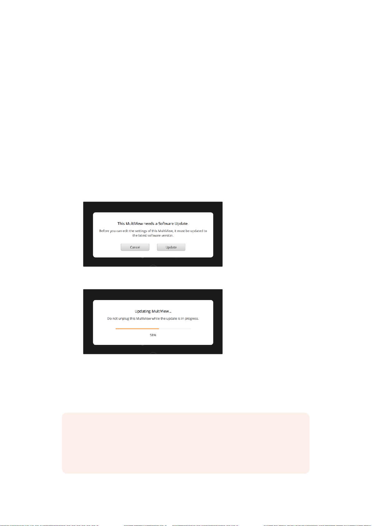
Updating the Internal Software
Occasionally, the internal software in your Blackmagic MultiView will need to be updated.
Updates to internal software can provide new features, compatibility with new hardware, and
support for new formats.
To update your Blackmagic MultiView internal software:
1 Connect your Blackmagic MultiView to your computer via USB or Ethernet.
2 Launch Blackmagic MultiView setup and it will automatically display any Blackmagic
MultiViews that are connected to your network.
3 Select your Blackmagic MultiView by clicking on the product image or the settings icon
below the product name.
4 Blackmagic MultiView setup will inform you if an update is required.
5 If an update is required, click the ‘update’ button and allow the software to install. Make
sure your Blackmagic MultiView is not unplugged while the update is in progress.
6 Click the ‘close’ button when the update is finished.
Click the ‘update’ button to install new internal software.
Make sure your Blackmagic MultiView is not
unplugged while the update is in progress.
Using Videohub Control Software
NOTE You can use Videohub Control software to route sources to views
onBlackmagic MultiView 16, plus other settings such as selecting the view for
solomode, or the audio source for the multi view output. On Blackmagic
MultiView4, you can use Videohub Control software to change audio source
for the multi view output.
2828Using Videohub Control Software
Page 29
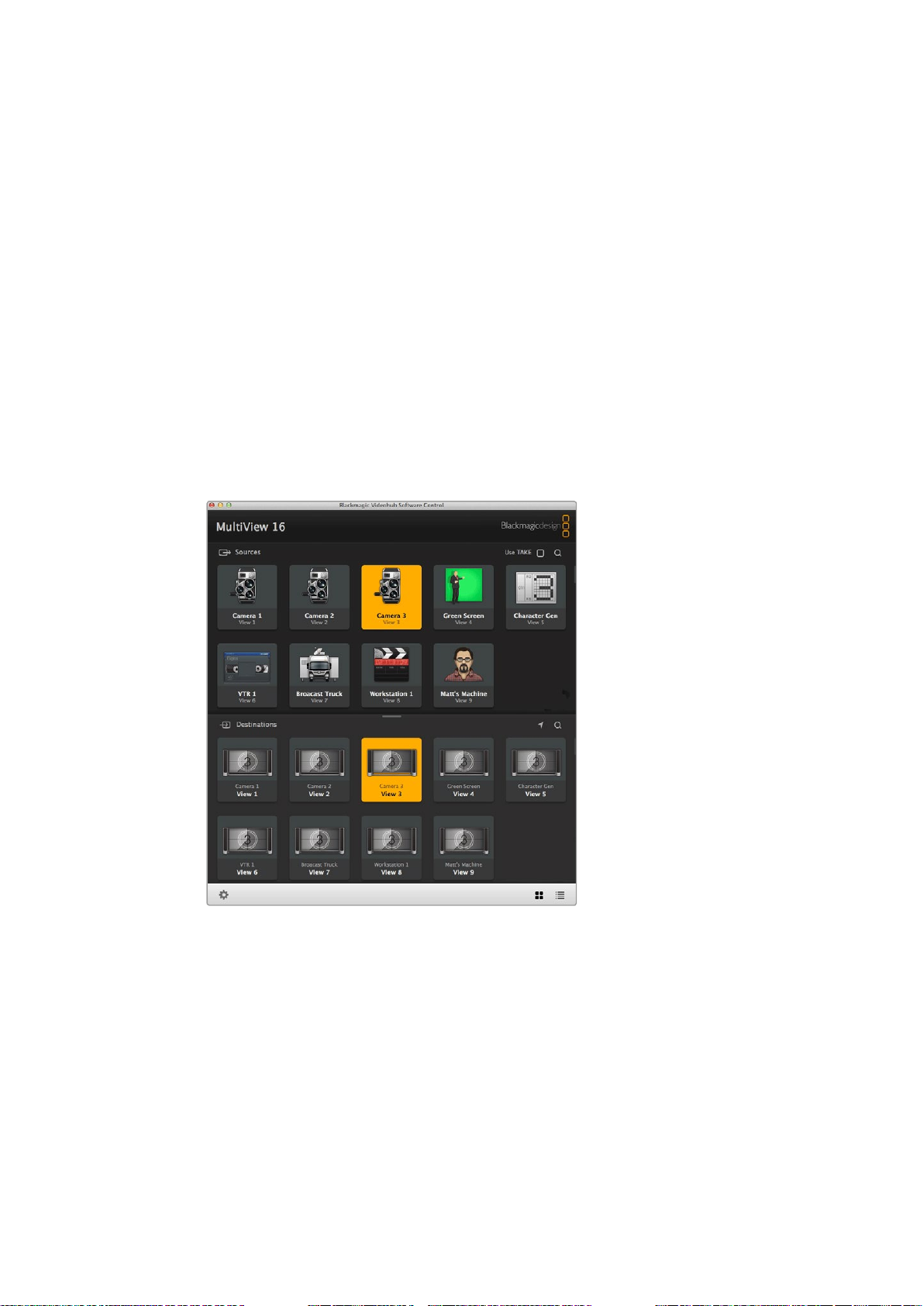
Controlling Blackmagic MultiView using
BlackmagicVideohub Control Software
When you have Blackmagic MultiView 16 connected to a network, you can use Blackmagic
Videohub Control on a Mac or Windows computer to route Blackmagic MultiView 16’s
videoinputs to different views within your multi view layout. Your Blackmagic MultiView’s
SDIinputs appear as pushbuttons within the ‘sources’ panel, while the views appear as
pushbuttons within the ‘destinations’ panel. The Videohub Control application is part of the
Videohub software installer which can be downloaded from the Blackmagic Design support
center at www.blackmagicdesign.com/support.
Select your MultiView 16
After launching the Videohub Control software, click on the gear icon to open the ‘settings’ pop
up menu, and choose “select Videohub”. Select your Blackmagic MultiView 16’s name from the
list of connected devices.
If your inputs are labelled, the names you assigned will appear within the Videohub Control
software. If they are not labelled they will display as Input 1, Input 2, Input 3, etc.
You can use Blackmagic Videohub Control to route
BlackmagicMultiView 16’s sources to different views.
Viewing your Inputs
To see which of your Blackmagic MultiView 16’s video inputs is routed to a particular view, click
a view pushbutton in the destinations panel. The destination, or view, button will illuminate. In
the ‘sources’ panel, the pushbutton of the routed video input will also illuminate, making it clear
which input, or source, is routed to the view.
Routing Inputs to Views
To route a video input to a view, click a view pushbutton from the destination panel, then click
an input pushbutton in the sources panel to immediately route that input to the view.
2929Using Videohub Control Software
Page 30
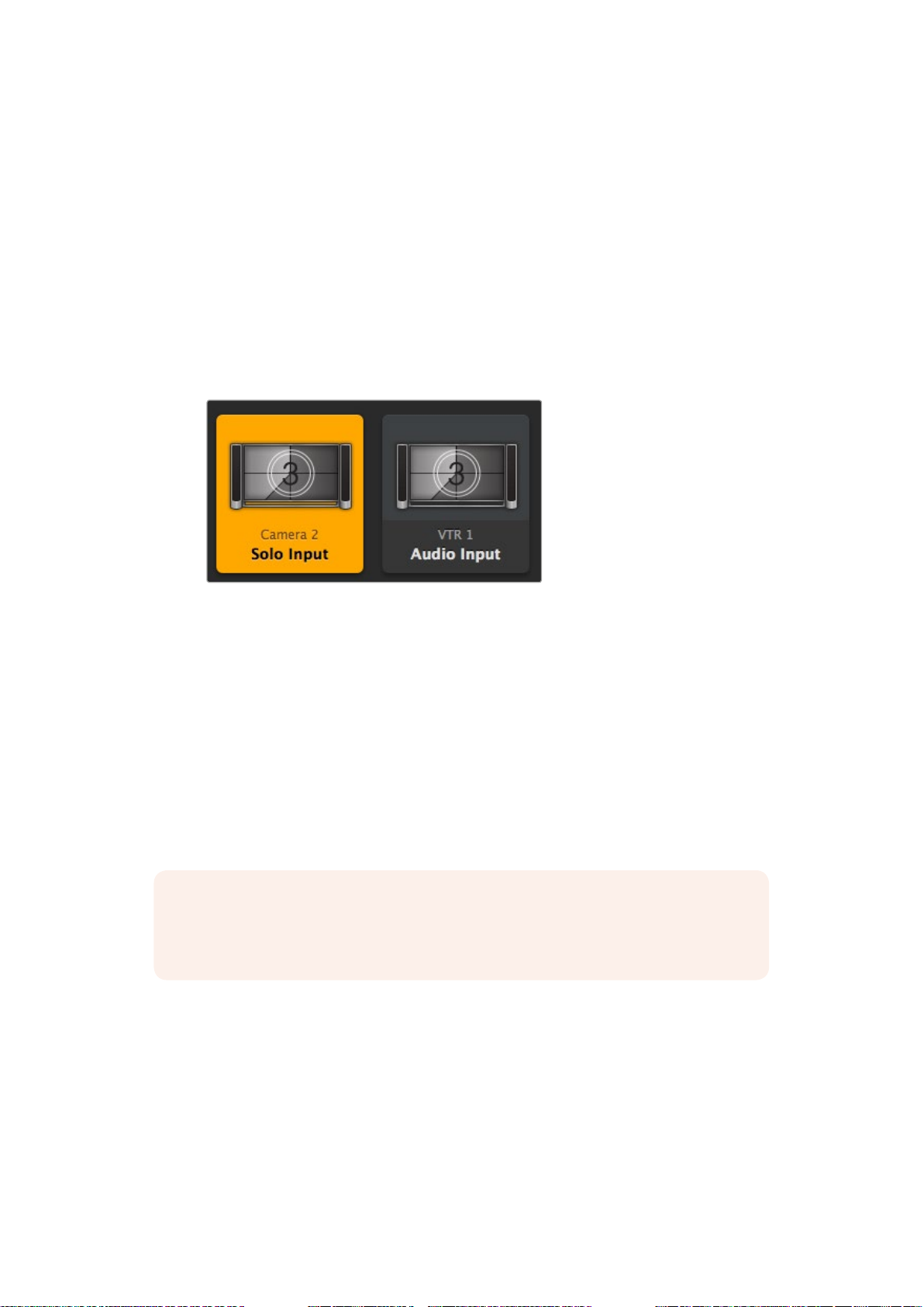
Solo Input
Use the “solo input” pushbutton to determine which input is displayed full screen when the
“solo” button is enabled on the Blackmagic MultiView 16’s front panel. Simply click on the “solo
input” pushbutton in the Videohub Control destinations panel, then click an input pushbutton in
the sources panel.
Audio Input
On Blackmagic MultiView 16 and Blackmagic MultiView 4 you can use the “audio input”
pushbutton in Videohub Control software to determine which SDI input’s audio is routed to the
multi view output. Simply click on the “audio input” pushbutton in the Videohub Control
destinations panel, then click an input pushbutton in the sources panel to immediately route
that input’s audio to the multi view output.
The “solo input” and “audio input” pushbuttons allow
you to change these settings using Videohub Control.
Developer Information
Blackmagic Videohub Ethernet Protocol v2.3
Summary
Your Blackmagic MultiView is compatible with the Blackmagic Videohub Ethernet Protocol. It is
text based and is accessed by connecting to your Blackmagic MultiView’s IP address and
TCPport 9990.
NOTE Controlling your MultiView via Ethernet is available on both models,
however, most features are relevant to Blackmagic MultiView 16. On Blackmagic
MultiView 4, you can change the source for the Multi View audio.
The multi view sends information in blocks which each have an identifying header in all caps,
followed by a full colon. A block spans multiple lines and is terminated by a blank line. Each line
in the protocol is terminated by a newline character.
Lines sent to the Blackmagic MultiView 16 can be terminated with line feed, carriage
return or both.
Upon connection, the multi view sends a complete dump of the state of the device. After the
initial status dump, status updates are sent every time the multi view status changes.
To be resilient to future protocol changes, clients should ignore blocks they do not recognize,
up to the trailing blank line. Within existing blocks, clients should ignore lines they do not
recognize.
3030Developer Information
Page 31

Protocol Preamble
The first block sent by the multi view is always the protocol preamble:
PROTOCOL PREAMBLE:↵
Version: 2.3↵
↵
The version field indicates the protocol version. When the protocol is changed in a compatible
way, the minor version number will be updated. If incompatible changes are made, the major
version number will be updated.
Device Information
The next block contains general information about the connected Blackmagic MultiView 16
device. If a device is connected, the multi view will report the attributes of the Blackmagic
MultiView 16:
MULTIVIEW DEVICE:↵
Device present: true↵
Model name: Blackmagic MultiView 16↵
Video inputs: 16↵
Friendly name:
Unique ID:
Video processing units: 0↵
Video outputs: 16↵
Video monitoring outputs: 0↵
Serial P o r t s:
↵
This example is for the Blackmagic MultiView 16 which has 16 sources and 18 views including
solo which is view 16 and audio which is view 17, referred to here as outputs.
Legend
↵ line feed
… and so on
Version 2.3 of the Blackmagic Videohub Ethernet Protocol
was released with Videohub 4.9.1 software.
Initial Status Dump
The next two blocks enumerate the labels assigned to the input and output ports.
INPUT LABELS:↵
0 VTR 1↵
1 VTR 2↵
…
↵
OUTPUT LABELS:↵
0 Output feed 1↵
1 Output feed 2↵
…
↵
Note: Input and Output labels are always numbered starting at zero in the protocol which
matches port one on the chassis.
The next three blocks describe the routing of the view ports.
VIDEO OUTPUT ROUTING:↵
0 5↵
3131Developer Information
Page 32

1 3↵
…
↵
The next block describes the locking status of the views. Each port has a lock status of “O” for
ports that are owned by the current client (i.e., locked from the same IP address), “L” for ports
that are locked from a different client, or “U” for unlocked.
VIDEO OUTPUT LOCKS:↵
0 U↵
1 U↵
…
↵
The last block is the configuration block.
Layout: SOLO or 2x2 or 3x3 or 4x4
Output format: 50i or 50p or 60i or 60p
Solo enabled: True or False
Widescreen SD enable: True or False
Display border: True or False
Display labels: True or False
Display audio meters: True or False
Display SDI tally: True or False
Status Updates
When any route, label, or lock is changed on the multi view by any client, the multi view resends
the applicable status block, containing only the items that have changed.
If multiple items are changed, multiple items may be present in the update:
OUTPUT LABELS:↵
7 New output 8 label↵
10 New output 11 label↵
↵
Requesting Changes
To update a label, lock or route, the client should send a block of the same form the multi view
sends when its status changes. For example, to change the route of output port 8 to input port
3, the client should send the following block:
VIDEO OUTPUT ROUTING:↵
7 2↵
↵
The block must be terminated by a blank line. On receipt of a blank line, the multi view will
either acknowledge the request by responding:
ACK↵
↵
or indicate that the request was not understood by responding:
NAK↵
↵
After a positive response, the client should expect to see a status update from the MultiView
showing the status change. This is likely to be the same as the command that was sent, but if
the request could not be performed, or other changes were made simultaneously by other
clients, there may be more updates in the block, or more blocks. Simultaneous updates could
cancel each other out, leading to a response that is different to that expected.
For MultiView 16 the client can change the solo source and the audio source to embed on
the output.
Solo mode needs to be enabled either from the front panel or by sending the block:
3232Developer Information
Page 33

CONFIGURATION:↵
Solo enabled: true↵
↵
Once enabled the following block will change the SOLO source to input 11:
Video Output Routing:↵
16 10↵
↵
This is not available on MultiView 4.
The following block will send embedded audio from input 1 to the MultiView 16 output:
Video Output Routing:↵
17 0↵
↵
The following block will send embedded audio from input 1 to the MultiView 4 output:
Video Output Routing:↵
5 0↵
↵
In the absence of simultaneous updates, the dialog expected for a simple label change is
as follows:
OUTPUT LABELS:↵
6 new output label seven↵
↵
ACK↵
↵
OUTPUT LABELS:↵
6 new output label seven↵
↵
The asynchronous nature of the responses means that a client should never rely on the desired
update actually occurring and must simply watch for status updates from the MultiView and use
only these to update its local representation of the server state.
Requesting a Status Dump
The client may request that the MultiView resend the complete state of any status block by
sending the header of the block, followed by a blank line. In the following example, the client
requests the MultiView resend the output labels:
OUTPUT LABELS:↵
↵
ACK↵
↵
OUTPUT LABELS:↵
0 output label 1↵
1 output label 2↵
2 output label 3↵
…
↵
Checking the Connection
While the connection to the MultiView is established, a client may send a special no-operation
command to check that the MultiView is still responding:
PING:↵
↵
If the MultiView is responding, it will respond with an ACK message as for any other
recognized command.
3333Developer Information
Page 34

Blackmagic MultiView 16 RS-422 Protocol
LOOP OUT
IN
HDMI OUT 6G-SDI OUT HD-SDI OUT
11 12 13 14 15 16
RS-422
CNTRL
1 2 3 4 5 6 7 8 9 10 11 12 13 14 15 16
General
The RS-422 protocol can be used to control Blackmagic MultiView 16 as a slave device from
third party routers and automation systems.
The “Leitch Server” mode implements the router (server) side of the Leitch Serial Pass Through
Protocol as specified in section 4 of Leitch document SPR-MAN revision D. In “Leitch Client”
mode, the Blackmagic MultiView 16 implements the controller (client) side of the Leitch terminal
protocol. Set the desired leitch mode in the ‘configure’ settings in the Blackmagic MultiView
Setup software.
This document describes the commands and parameters in the protocol that are relevant and
supported by Blackmagic MultiView 16. Other commands and parameters specified in the
Leitch protocol are accepted but ignored.
The RS-422 serial port is configured as 9600 N81:
9600 is the line speed, or baud rate, at 9600 bits/sec.
N represents no parity check, or ‘none’.
8 is the data length.
1 is for stop bits.
To summarize N81, data without a parity check begins with 1 start bit, includes 8 true data bits,
and 1 stop bit. There are 10 bits in total.
The protocol is line oriented, with a maximum length of 250 characters per command. Each
command from the client should be terminated with a carriage return (\r). Each response from
the server will be terminated with a carriage return and line feed (\r\n).
Sources, destinations and levels are always specified in base-16, numbered from zero. Levels
are always between 0 and 15 (“F”) . Blackmagic MultiView 16 only has one valid level level zero.
On connecting to the serial port, the client should send a carriage return. Blackmagic MultiView
16 will respond with a
> character prompt, which is not followed by a carriage return or line feed.
Receiving the prompt indicates that a connection has been established. The same prompt will
be issued after each command received by the MultiView.
In the following documentation, commands in
orange and values in blue must be typed literally,
including any spaces. In the following example of an immediate command using destination
port 7 and source port 3,
@ X:0/destination,source would be entered as: @ X:0/6,2
REF IN
ETHERNET SD/HD/3G/6G-SDI IN
1 2 3 4 5 6 7 8 9 10
RS-422
CNTRL
USB
The RS-422 serial port lets you control Blackmagic MultiView 16 from third party routers and
automation systems. The connector is an RJ11 connector, the same used in many landline
telephone connections. By modifying an RS-422 to USB adapter cable terminated with an
RJ11connector, you can control Blackmagic MultiView 16 using external controllers via USB.
3434Developer Information
Page 35

An RS-422 to USB adapter cable and RJ11 connector can be purchased
from electronics stores such as Digi-Key.com. Refer to the pinout
diagram below for help wiring the RJ11 connector to the adapter cable.
Pin No. Function
Pin 1
Pin 2
Pin 3
Pin 4
Pin 5
Pin 6
Pinout diagram for the RJ11 connector.
TX +
TX -
GND
GND
RX -
RX +
Notifications
Once connected, if status reporting is enabled, the client will receive a notification message
when a route changes on the MultiView. The notifications take one of two forms:
S:0destination,source Routing change
This message indicates that the specified source port is now routed to the specified
destination.
V:0 destination,source Preset routing notification
This message indicates that the current preset includes a route from the specified source to the
specified destination.
Global Commands
All pass through commands are preceded by an
@ symbol and a space.
The following client commands are supported:
@ ! disable status reporting
Status reporting is disabled by default.
@ ? enable status reporting
Status reporting is enabled.
@ Z: reset routing table
Routing is reset so that the first source is routed to all destinations.
3535Developer Information
Page 36

Immediate Commands
@ X:0/destination,source change route
@ X:0/destination,source/destination-2,source-2… change multiple routes
The specified source ports are routed to the specified destinations.
Any routing changes will trigger
@ X?0destination request individual route status
The source routed to the specified destination will be returned as an
@ S?0 request all ports route status
Each source and destination port pair will be returned as
S: notifications
S: notification.
S: notifications
Salvo Commands
@ P:0/destination,source queue route change
@ P:0/destination,source/destination-2,source-2… queue multiple route changes
The specified routing changes are added to the current salvo for later execution.
@ P?0destination request individual port status in salvo
If a routing change for the specified destination port is queued, the route will be
returned as a
@ V ?0 request all ports status in salvo
Each queued routing change in the salvo is reported as a
V: notification.
V: notification.
@ B:C clear salvo
@ B:R clear salvo
Any queued changes are discarded and the salvo is reset.
@ B:E execute salvo
Any queued changes are executed and each routing change will be returned as an
S: notification.
3636Developer Information
Page 37

Help
Getting Help
The fastest way to obtain help is to go to the Blackmagic Design online support pages and
check the latest support material available for your Blackmagic MultiView 16.
Blackmagic Design online support pages
The latest manual, software and support notes can be found at the Blackmagic Design support
center at www.blackmagicdesign.com/support.
Contacting Blackmagic Design support
If you can’t find the help you need in our support material, please use the “send us an email”
button to email a support request. Alternatively, click on the “find your local support team”
button and call your nearest Blackmagic Design support office.
Checking the version currently installed
To check which version of Blackmagic MultiView 16 is installed on your computer, open the
Blackmagic MultiView application. From the “Blackmagic MultiView” menu, select “About
MultiView” and note the version number.
How to get the latest updates
After checking the version of your Blackmagic MultiView 16 on your computer, please visit the
Blackmagic Design support center at www.blackmagicdesign.com/support to check for the
latest updates. While it is usually a good idea to run the latest updates, it is a wise practice to
avoid updating any software if you are in the middle of an important project.
3737Help
Page 38

Warnings
100-240V 1.0A 50-60Hz Fuse T1AL
Caution: Risk of Electric Shock
Any devices that connect to the data ports must comply with clause 4.7 of AS/NZS 60950.1.
Blackmagic MultiView 16 caution label
Blackmagic MultiView 4 caution label
3838Warnings
Page 39

Warranty
Limited Warranty
Blackmagic Design warrants that Blackmagic MultiView will be free from defects in materials
and workmanship for a period of 36 months from the date of purchase excluding connectors,
cables, cooling fans, fiber optic modules, fuses, keyboards and batteries which will be free from
defects in materials and workmanship for a period of 12 months from the date of purchase. If a
product proves to be defective during this warranty period, Blackmagic Design, at its option,
either will repair the defective product without charge for parts and labor, or will provide a
replacement in exchange for the defective product.
In order to obtain service under this warranty, you the Customer, must notify Blackmagic Design
of the defect before the expiration of the warranty period and make suitable arrangements for
the performance of service. The Customer shall be responsible for packaging and shipping the
defective product to a designated service center nominated by Blackmagic Design, with
shipping charges pre paid. Customer shall be responsible for paying all shipping changes,
insurance, duties, taxes, and any other charges for products returned to us for any reason.
This warranty shall not apply to any defect, failure or damage caused by improper use or
improper or inadequate maintenance and care. Blackmagic Design shall not be obligated to
furnish service under this warranty: a) to repair damage resulting from attempts by personnel
other than Blackmagic Design representatives to install, repair or service the product, b) to
repair damage resulting from improper use or connection to incompatible equipment, c) to
repair any damage or malfunction caused by the use of non Blackmagic Design parts or
supplies, or d) to service a product that has been modified or integrated with other products
when the effect of such a modification or integration increases the time or difficulty of servicing
the product. THIS WARRANTY IS GIVEN BY BLACKMAGIC DESIGN IN LIEU OF ANY OTHER
WARRANTIES, EXPRESS OR IMPLIED. BLACKMAGIC DESIGN AND ITS VENDORS DISCLAIM
ANY IMPLIED WARRANTIES OF MERCHANTABILITY OR FITNESS FOR A PARTICULAR
PURPOSE. BLACKMAGIC DESIGN’S RESPONSIBILITY TO REPAIR OR REPLACE DEFECTIVE
PRODUCTS IS THE WHOLE AND EXCLUSIVE REMEDY PROVIDED TO THE CUSTOMER FOR
ANY INDIRECT, SPECIAL, INCIDENTAL OR CONSEQUENTIAL DAMAGES IRRESPECTIVE OF
WHETHER BLACKMAGIC DESIGN OR THE VENDOR HAS ADVANCE NOTICE OF THE
POSSIBILITY OF SUCH DAMAGES. BLACKMAGIC DESIGN IS NOT LIABLE FOR ANY ILLEGAL
USE OF EQUIPMENT BY CUSTOMER. BLACKMAGIC IS NOT LIABLE FOR ANY DAMAGES
RESULTING FROM USE OF THIS PRODUCT. USER OPERATES THIS PRODUCT AT OWN RISK.
© Copyright 2016 Blackmagic Design. All rights reserved. ‘Blackmagic Design’, ‘DeckLink’, ‘HDLink’, ‘Workgroup Videohub’,
‘Multibridge Pro’, ‘Multibridge Extreme’, ‘Intensity’ and ‘Leading the creative video revolution’ are registered trademarks in the
US and other countries. All other company and product names may be trademarks of their respective companies with which
they are associated.
3939Warranty
Page 40

インストール/オペレーションマニュアル
Blackmagic
MultiView
2016年8
日本語
月
Page 41

ようこそ
このたび は
私たちは、誰もが最高品質の映 像を使 用できるようにすることで、テレビ業界を真にクリ
エイティブな業界にするという夢を、ユーザーの皆様と共 有 できればと考えています。
MultiView 16
独 立した 放 送 用 モニターと 同 等 の 働 きをしま す。
ルのマルチソースモ ニタリングを実 現 で きるので す!
HD、Ultra HD
あるいは移動型のプロダクションに最適です。1台の
ティングして組み合わせることで、独自のモニタリング 設 定をカスタマイズすることもできます!
このマニュアルには 、
て い ま す 。し か し 、IPアドレスやコンピューターネットワー クに関してあまり詳しくない 場 合は 、技 術
アシスタントに協力を求めた方が良いでしょう。
トウェ ア でコントロ ー ルで きま す。
インストール後にやや技術的な環境設定がいくつか必要となります。
弊 社のウェブサイト
ソフトウェアの 最新バージョンをダウンロ ードしてください 。最 後 に、ソフトウェア・アップデート
をダウンロードする際にお手元の
アのリリース時にお客様にお知らせいたします。私たちは、常に新機能の開発および製品の改善
に努めていますので、ユーザーの皆様からご意見をいただければ幸いです。
Blackmagic MultiView
は、今日市場に出回っている低価格の
スクリーン で 最 大4系 統 のモニタリング が 可 能 な
Blackmagic Multiview
www.blackmagicdesign.com/jp
をお買い求めいただき誠にありがとうございました。
Ultra HD
MultiView 16
MultiView
をインストールする際に必要な情報がすべて記載され
Blackmagic MultiViewは、Videohub Control
Videohub Control
Blackmagic MultiView
ソフトウェアは 簡単 にインストールで きます が 、
の サ ポ ー ト ペ ー ジ で 、同 マ ニ ュ ア ル お よ び
テ レ ビ と 使 用 す る こ と で 、最 大16台の
はわずかな費用で真の放送局レベ
Blackmagic MultiView 4
からの出力を別の
を登録いただければ、新しいソフトウェ
は 、小 規 模 、
MultiView
にルー
ソフ
Blackmagic MultiView
ことを 願 って い ま す。
を 長 年 に わ た ってご 使 用 い た だ き 、
Blackmagic Design CEO
グ ラ ント・ペ テ ィ
Ultra HD
の映 像 をお楽し みいただける
Page 42

目次
BlackmagicMultiView
はじめに
電源の接続
SDI
ソースおよびモニターの接続
マルチビューレイアウトの設定
ネットワ ークに 接 続
シリアルコントロール 接 続
ラックにインストール
MultiView
複数の
設定の変更
Blackmagic MultiView 16
TeranexMiniSmartPanel
Teranex Mini Smart Panel
Teranex Mini Smart Panel
コントロールボタンと回転ノブ
Teranex Mini Smart Panel
スイッ チ を 使 用 して 設 定 を 変 更
スイッ チ 設 定
BlackmagicMultiViewSetup
Blackmagic MultiView Setup
Blackmagic MultiView Setup
Blackmagic MultiView Setup
ソ ー ス(
ビ ュ ー(
コ ン フィ ギ ュ レ ー シ ョ ン(
ラベ ル の 保 存とロード
内部ソフトウェアのアップデート
Sources
Views
を使用
のフロントコントロールパネル
を使 用して 設 定 を 変 更
のインストール
の機能
を 使 用 して 設 定を 変 更
の使用
のインストール
のホームページ
を 使 用 して 設 定を 変 更
)
)
Configure
)
43
43
43
44
45
46
46
46
47
48
53
53
54
54
55
57
58
59
59
60
61
61
62
62
65
66
VideohubControl
Blackmagic Videohub Control
DeveloperInformation
Blackmagic Videohub Ethernet Protocol v2.3
Blackmagic MultiView 16 RS-422 Protocol
ヘルプ
注意
保証
ソフトウェアの 使 用
ソフトウェア で
Blackmagic MultiView
をコントロール
66
67
68
68
72
75
76
77
目次
Page 43

はじめに
MultiView 4
Blackmagic
4
31
2
HDMI OUT
HD
UHD
OUT
SD/HD/3G/6G-SDI IN
MultiView 4
Blackmagic
Blackmagic MultiView
は 、電 源 を 入 れ て
接続するだけで簡単に使用できます。同セクションでは、
SDI
ビデオソースを接続し、モニターやテレビを
Blackmagic MultiView
に必要なすべての項目を説明します。
電源の接続
Blackmagic MultiView
に 電 源 を 供 給 す る に は 、リ ア パ ネ ル の
コードを差し込みます。
作業のこつ
Blackmagic MultiView 4はPoE+
をサ ポートしてい る た め、
たイー サ ネットスイッチ に 接 続 するだ け で 使 用 で きます。
SDI
ソースおよびモニター の 接 続
SDI
ソ ー ス を 、リ ア パ ネ ル に あ る
出さ れ 、マルチビュー出力に 表 示され ます。出 力を 確 認するには 、モニターをHD、
ビュー出 力 に接 続しま す。
ETHERNET
2
SDI
ビデオ入力のいずれかに差し込みます。ビデオフォーマットが自動検
HD
UHD
OUT
4
31
SD/HD/3G/6G-SDI IN
HDMI OUT
110-240V AC
電源入力に標準
HDMI/SDI
出力に
の使用を開 始するため
IEC
電源
PoE+
に対応し
6G-SDI、HDMI
マルチ
Blackmagic MultiViewのSDI
31
SD/HD/3G/6G-SDI IN
4
HDMI OUT
2
ETHERNET
Blackmagic MultiViewのHDMI
HDMI
出力に接続すると、
ビデオ入 力に 接 続。
HD
UHD
OUT
HDMI OUT
あるいは
SDI
マルチビュー出力に接 続 。
Blackmagic MultiView
HD
UHD
OUT
はモ ニターが
Ultra HD
HDMI
ビデオソースを
モニターを
モニターを
サポートしているか を自動的に検出し、それに従いマルチビュー出力を 切り替えます。
作業のこつ
Blackmagic MultiView 16
Ultra HDを6G-SDI
および
では、マルチビューを専用
HDMI
出力から出力できます。
HD-SDI
あるいはHDを
出力から、
はじめに
4343
Page 44

ま た 、各
LOOP OUT
IN
HDMI OUT 6G-SDI OUT HD-SDI OUT
HDMI OUT 6G-SDI OUT HD-SDI OUT
SDI
可能 です。
入力の上にあるループ出力を使用して、入力ソースを他のビデオ機器に接続することも
1 2 3 4 5 6 7 8 9 10 11 12 13 14 15 16
REF IN
RS-422
CNTRL
ETHERNET SD/HD/3G/6G-SDI IN
USB
作業のこつ
HD
およびHDのマルチビュー モ ニタリング 用にすべ て同時 に 使 用 で きます。
Blackmagic MultiView 4
Smart Panel
Blackmagic MultiView 16
で は 、内 蔵 ス イ ッ チ 、オ プ シ ョ ン の
、ま た は
Blackmagic MultiView Setup
ア を 使 用 し て 、マ ル チ ビ ュ ー 出 力 を
マルチビューレイアウトの設定
に搭載された
Ultra HD
LOOP OUT
IN
HDMI OUT 6G-SDI OUT HD-SDI OUT
SDI/HDMI
Teranex Mini
出力は、
Ultra
ユー ティリティソフトウェ
またはHDで切り替えられます。
必要に応じてマルチビューレイアウトを変更できます。例えば、
ソロビュー に 設 定 可 能 で す。
BlackmagicMultiView16
Blackmagic MultiView 16
ロールパ ネル の
することで、いずれか のビデオをフルスクリーンでモニタリングできます。
1
フロントコントロ ールパネル の「
2
「
に進むと常にハイライトされています。「
3
「
設定では、1つのスクリーン で16系統のソースビューを確認できます。設 定を変 更すると、「
ボ タ ン と「
す る に は「
4
「
Blackmagic MultiView 16は、2x2、3x3、4x4
でレイア ウトを 設 定
のレイアウトを変 更したい 場 合は 、コントロールボタン、回 転ノブ、内 臓コント
LCD
を 使 用 し ま す 。 ま た 、「
Settings
Layout
SET
」メ ニ ュ ー の 最 初 の 設 定 は「
」設 定でフロントコントロ ールパ ネ ル の回転 ノブを 使 用し 、「
MENU
」ボタンが点滅し始めます。設定の変更を確認するには「
MENU
」ボ タ ン を 押 し ま す。
」ボ タ ン を 押 し て 設 定 を 決 定 し ま す。
SOLO
」ボ タ ン を 押 し 、次 に「
MENU
」ボ タ ン を 押 し 、
Layout
SET
」で す 。し た が っ て こ の 設 定 は「
」ボ タ ン を 使 用 し て 設 定 を 変 更 し ま す。
Blackmagic MultiView 4は、2x2
、そ し て ソ ロ ビ ュ ー に 設 定 可 能 で す 。
VIEW
」ボ タ ン を 押 し て ビ ュ ー を 選 択
LCDで「Settings
」ス ク リ ー ン を 開 き ま す 。
Settings
4x4
」を 選 択 し ま す。
SET
」ボ タ ン を 、キ ャ ン セ ル
あるいは
」メ ニ ュ ー
4x4
SET
はじめに
の
」
4444
Page 45

Blackmagic MultiView 16 Setup
LOOP OUT
IN
HDMI OUT 6G-SDI OUT HD-SDI OUT
16
SOLO
SET
SRC
VIEW
MENU
LOOP OUT
IN
HDMI OUT 6G-SDI OUT HD-SDI OUT
SRC
VIEW
MENU
LOOP OUT
IN
HDMI OUT 6G-SDI OUT HD-SDI OUT
することも可能 です。
1
4
7
10
2
5
8
11
3
6
9
12
ソ フ ト ウ ェ ア の 、「
13
16
14
SOLO
VIEW
15
SET
MENU
Configure Control Panel
SRC
」で レ イ ア ウ ト を 設 定
Blackmagic MultiView 16
を押して、次に回転ノブを使ってレイアウトを選択し、「
押します。
4x4
の設定では、1つのスクリーンで16ビュー を確 認 できま す。
BlackmagicMultiView4
Blackmagic Multiview 4
Solo
を「
」に 変 更 す る に は 、
のデフォルトビュー は
Teranex Mini Smart Panel
の ビ ュ ー レ イ ア ウト を 設 定 す る に は ま ず「
SET
でレイア ウトを 設 定
2x2
レ イ アウトで す。
に あ る「1」のコントロールボタンを押します。
MENU
」ボ タ ン を
Blackmagic MultiView 4
の デ ィ ス プ レ イ モ ー ド に 戻 す に は「2」ボ タ ン を 押 し ま す。
Setup
ソ フ ト ウ ェ ア の「
Blackmagic MultiView 4
「1」ボタンでソロビュー、「2」ボ タ ン で
ネットワ ー クに 接 続
Blackmagic MultiViewは、Blackmagic Videohub Ethernet Protocol
Configure
1 MENU
2 VIDEO
SET AUDIO
」設定を使用してレイアウトを設定することも可能です。
2160p 29.97 Input 3
1 3
2 4
のビューレイアウトの変更は
2x2
モード に な りま す。
を サ ポ ー ト し て い ま す 。し た が って 、
直接アクセスしにくい場所にユニットをインストールしている場 合でも、
Master Control
イーサ ネット経 由 で ネットワ ークに 接 続 すると 、
のコンピュー ターや
MultiView 16
をリモ ートコントロ ールで きま す。
Blackmagic Videohub
などの
Videohub
コントロールパネルから簡単にリモートコントロールできます。
Blackmagic MultiView
からも認 識できるようになります。これらのデバイスから
は同ネットワークに接続された他
」
でレイアウト
Blackmagic Smart Control
Blackmagic
2x2
や
Blackmagic MultiView
1Blackmagic MultiView
2
をネット ワ ー ク に 接 続 す る:
標準
RJ45
イーサ ネットケーブル を 使 用 して、
ピューターに 接 続 します。
に電 源を 入 れ ます。
Blackmagic Multiview
をネットワ ー クあ る い は コン
ラックに インストー ル
4545
Page 46

ネットワ ークに 接 続した ら 、
ることを 確 認 しま す。
MultiView 4
また
てネットワーク設 定を変 更することもできま す。ネットワーク設 定 変 更に 関 する詳 細は 、同 マニュアル の
「設定の変更」セクションを参照してください。
を使 用している場合、ネットワーク設定をコントロールパネルの
Blackmagic MultiViewをUSB
Blackmagic MultiviewのIP
Blackmagic MultiView 16
経由 でコンピュー ターに接 続 し、
アドレス が ネット ワ ー ク上 の 他 の 機 器 と 異 な って い
、あ る い は
Teranex Mini Smart Panel
LCD
メニュー か ら変 更 できます。
Blackmagic MultiView Setup
をインストールした
を使っ
シリアルコントロ ール 接 続
サードパー ティ製 のル ー ターコントロ ー ラ ーで も 、
16
をコントロールできます。シリアルコントロールに関する詳細は、同マニュアルの「
Setup
を 使 用 して 設 定を 変 更 」セクションを 参 照してください 。
RS-422
シリアル 接 続 を 使 用して
Blackmagic MultiView
Blackmagic MultiView
ラックにインストール
Blackmagic MultiView 16は、1U
こ れ に 対 し 、小 型 の
も使 用で きま す。
可能 です。
できるよう設計されているので、ユ ニットを簡 単に接続して必要な 数 だけソースビューを構 築できます。
Teranex Mini Rack ShelfへのBlackmagic MultiView 4
を取り外し、底のマウントホールを使って
The Teranex Mini Rack Shelf
だけ使用している場合でもラックの隙間を埋めることができます。
詳細は、
MultiView 4をTeranex Mini Rack Shelf
Teranex Mini Rack Shelf
Mini Rack Shelf
Blackmagic Teranex Mini Rack Shelfは、1U
Blackmagic Design
Blackmagic MultiView 4
MultiView 4
にインストールしたら 、すべてのコネクター は 通常通りユ ニットの 後 部からアクセスできま す。
ラックサイズなので、あらゆる放 送 用ラック、ロードケースに収 納 で きます。
は放 送 用ラックなどを 使 用しない 移動 型 プ ロ ダクションで
は小型で可搬性に優れた設計になっていますが、ラックに収納することも
のスペース に3台までのユニットを並べてマウント
のインストールは非常に簡単です。ゴム製の足部
Teranex Mini Rack Shelf
には、オリジナルのカバーパネルが2つ含まれており、
ウェブ サイト
が専門家により機材ラックにマウントされていることを確認してください。
www.blackmagicdesign.com/jp
にインストールする場合、ユニット底面の電気定格が覆われるため、
の底 に ユ ニット をネジ で 取り 付け ま す。
MultiView 4を1
を 参 照 してくだ さ い 。
台
Teranex
複数の
複数の
これ は、マルチビュー出力にさらにビューソースを追 加したい 場合 に 役 立ちま す。1台の
力を もう1台の入力に接続することで、マルチビュー出力にソースビューを追加できます。アップストリーム
のマルチビュー出力は、クリアなイメージを得るため、
MultiView
Blackmagic MultiViews
を使用
を組み合わせて使用することで、独自のモニタリング設定を実現できます。
Ultra HD
MultiView
モニター に 接 続 することを 推 奨します。
複数の
の出
MultiView
を使用
4646
Page 47

1 2 3 4 5 6 7 8 9 10 11 12 13 14 15 16
MultiView 4
Blackmagic
REF IN
RS-422
CNTRL
ETHERNET SD/HD/3G/6G-SDI IN
USB
HD
UHD
OUT
4
2
31
ETHERNET
SD/HD/3G/6G-SDI IN
HDMI OUT
LOOP OUT
IN
HDMI OUT 6G-SDI OUT HD-SDI OUT
1台のMultiView
の出力をもう1台の入 力に ル ーティン グ するこ
とで、マルチビュー レイアウトにビュー を 追 加できます。
MultiView
Blackmagic MultiView
の使用を開始するのに必要な作業はこれだけです。設定の変更、ビューの名称設定など、
の活用に関する詳細は、同マニュアルの次のセクションを読み進めてください。
設定の変更
Blackmagic MultiView
フロントコントロ ールパネル-
蔵 し て い る の で 、ユ ニ ッ ト の 正 面 か ら 簡 単 に 設 定 を 変 更 で き ま す 。
ス イッ チ -
設 定 を 変更で きます。フロントパ ネル のゴム製ダ ストカバー を 開くとこれらのスイッチにアクセ
スできます。スイッチ設 定の説 明 図は、ユニット底 面に記 載されているので、各スイッチの設定
を簡 単 に確 認で きま す。
TeranexMiniSmartPanel - Blackmagic MultiVIew 4
ョンの
使 用 で き る よ う に な り ま す 。こ れ は 、
ほぼ 同じように機能し、簡単かつ直 感 的なローカルコントロールが 可能 です。
BlackmagicMultiViewSetup -
イーサ ネット経 由 で コ ン ピ ュー タ ー を 使 用して 設 定を 変 更で きま す。詳 細 は 、「
MultiView Setup
VideohubControl
Blackmagic Videohub Control
オーディオ入力ソースの選択が 可 能 です。詳 細は「
ション を 参 照してください 。
の設定を変更するにはいくつかの方法があります。
Blackmagic MultiView 4
Teranex Mini Smart Panel
」セ ク シ ョン を 参 照 し て く だ さ い 。
Blackmagic MultiView 16
ソフトウェア -
ソフトウェアを使用してソースのルーティング、ビューの変更、
はコントロールパネルおよび
LCD
のフロントパネルにあるスイッチは 、ペンを使用して即座に
のオリジナル のフロントパ ネ ル を オプシ
に置き換えると、内 蔵コントロールボタン、回 転ノブ、
Blackmagic MultiView 16
このセットアップソフトウェアを使 用 すると、
のフロントコントロールパネルと
USB
あるいは
Blackmagic
Blackmagic MultiView
がネットワークに接続されている場合、
Videohub Software Control
の 使 用 」セ ク
LCD
を内
を
設定の変更
4747
Page 48

BlackmagicMultiView16
ETHERNET SD/HD/3G/6G-SDI IN
REF IN
LOOP OUT
IN
HDMI OUT 6G-SDI OUT HD-SDI OUT
RS-422
CNTRL
USB
1 2 3 4 5 6 7 8 9 10 11 12 13 14 15 16
1
2
3
4
5
6
7
8
9
10
11
12
13
14
15
16
SOLO
SET
SRC
VIEW
MENU
LOOP OUT
IN
HDMI OUT 6G-SDI OUT HD-SDI OUT
のフロントコントロールパネル
Blackmagic MultiView 16
Blackmagic MultiView 16
のフロントコントロールパ ネル を 使 用 す れば 、非 常に 簡単に設 定を変 更 で きます。
に 電 源 を 入 れ る と 、内 蔵
LCD
にホームスクリーンが 表 示 されま す。ホームスク
リーンはデフォルト表示で、以下を含む設定項目の概要を確認できます:
マルチビュー出力フレームレート-スクリーン 左 上 にありま す。
Ultra HD SDI
に選 択されてい るフレームレートが 表 示さ れます。
オ ー デ ィ オ 入 力 -マルチビュー出 力フレームレートの 隣 です。
のエ ン ベデッド オ ー ディ オ 用に 使 用 してい る
SDI
入力が表示されます。
HDMI/SDI
マ ル チ ビ ュ ー レ イ ア ウ ト -選 択しているマル チビューレ イアウトが表 示されます。
ホーム スクリーンは 、
ルパネル
LCD
スプレ イは 、選択したマル チビューレイアウト、マルチビュ
SDI
ー
出力のフレ ームレート、マルチビュー出 力 用のエンベ
デッドオー ディオ に選 択し た
Blackmagic MultiView 16
コントロ ー
の デ フ ォ ル ト 表 示 で す 。こ の ス ク リ ーン デ ィ
SDI
入 力 を 表 示しま す。
マルチビュー出 力
マルチビュー出 力 信号
コントロールパネルボタン
Blackmagic MultiView 16
ス/ビュー の 設 定 が 可 能 で す。
Blackmagic MultiView 16
Blackmagic MultiView 16
ユニットの正面から簡 単に設定変 更、ビューの切り替えが可能 。
SOLO
ボタン
1
つ の ビ ュ ー を フ ル ス ク リ ー ン で 表 示 す る に は 、「
ビ ュ ー ボ タ ン を 押 す と 、選 択 し た ビ ュ ー が フ ル ス ク リ ー ン モ ー ド に な り ま す。もう 一 度「
マル チビューレ イア ウト に 戻ります。
のコントロールパネルの発光ボタンを使 用すれば、簡単に設 定の調整や、ソー
1
4
7
10
13
16
2
5
8
3
11
6
9
12
のコントロールパ ネルボタンを 使 えば、
SOLO
」ボタンを押します。次にコントロールパネルの
SRC
14
SOLO
VIEW
15
SET
MENU
SOLO
」ボ タ ン を 押 すと 、
設定の変更
4848
Page 49

SOLO
「
」機能を 使い、フルスクリー
ン モ ード で モニタリング。
MENU
「
再 度「
SET
設 定 を 調 整 す る に は「
て変 更 を 確 認 します。
「
これらのボタンを使用して、ビューに表示する入力ソースを選 択します。設定メニューをナビゲートする際は、
「
ボタン
MEMU
」ボタンを押すと、設定スクリーンが開きます。回転ノブと設定ボタンを使って設定を変更します。
MENU
」ボ タ ン を 押 し て ホ ー ム ス ク リ ー ン に 戻 りま す。
ボタン
SRC/VIEW
SRC/VIEW
」ボタンを使 用して設定オプションを上下に移 動することも可能です。
」ボ タ ン
SET
」 ボ タ ン を 押 し ま す 。 設 定 を 変 更 し た ら 、も う 一 度 「
SET
」ボ タ ン を 押 し
回転ノブ
回 転 ノ ブ は 、設 定 項 目 の ス ク ロ ー ル や 、設 定 ス ク リ ー ン の ア イ テ ム 選 択 な ど に 使 用 で き ま す 。選 択 を 誤 っ
てしまった場合は、回転ノブを押して前の設定に戻ります。
回転ノブ を時計回り/反 時 計 回 り に 回 し て 、メ ニ ュ ー 内 の2つのオプションから選択します。回転ノブを押
す と 、設 定 の オ ン/オフを 切り替えられ ま す。
BlackmagicMultiView16
Blackmagic MultiView 16
機能があります。これらの設定を調整することで、ビューの配置を簡単に変更できます。例えば、
5
をビュー1に配 置したいとい う 場 合 で す。
のソースとビュー の設 定
の重要な機能のひとつに、接続した
SDI
ソースを様々なビュー に割り当てら れ る
SDI
入力
ソースを ビュー に 割 り 当 て る:
1
フロントコントロ ールパネル の「
選 択 が ブル ーで ハ イライトさ れ ます。
2
数 字 付 きビューボタンを 押してビュー を 選 択します。または 、回 転ノブ を 使 用してビュー を スク
ロ ー ル し ま す 。「
3
SRC
「
4
5
「
」ボ タ ン を 押 し ま す。
コントロールパネル の 数 字付きビューボタンを押して入力を選 択します。または 、回転ノブを 使
LCD
用して
SET
」ボ タ ン を 押 し て 設 定 を 確 定 し ま す。
SET
の入力オプションをスクロールします。
VIEW
」ボタンを 押して、ビュー 選択 スクリーンを 開 きます。ビュー
」ボ タ ン を 押 し て 設 定 を 確 定 し ま す。
LCD
のソース 選 択 が ハイラ イトされ ま す。
設定の変更
4949
Page 50

Blackmagic MultiView 16
ETHERNET SD/HD/3G/6G-SDI IN
REF IN
LOOP OUT
IN
HDMI OUT 6G-SDI OUT HD-SDI OUT
RS-422
CNTRL
USB
1 2 3 4 5 6 7 8 9 10 11 12 13 14 15 16
16
SOLO
SET
SRC
VIEW
MENU
LOOP OUT
IN
HDMI OUT 6G-SDI OUT HD-SDI OUT
SRC
VIEW
LOOP OUT
IN
HDMI OUT 6G-SDI OUT HD-SDI OUT
1
4
7
10
13
16
2
5
8
3
11
6
9
12
SRC
14
SOLO
VIEW
15
SET
MENU
ソースをビューに配置 するには、「
選 択 し ま す 。次 に「
SET
」ボ タ ン を 押 し て 設 定 を 確 定 し ま す。
BlackmagicMultiView16
Blackmagic MultiView 16
入力を接続している場合は、「
は、マルチビュー出 力に表示するビューの 数 を 選 択 できます。例えば 、4系統の
2x2
VIEW
」ボ タ ン を 押 し て ビ ュ ー 設 定 を 開 き 、
でレイア ウトを 設 定
」レ イ ア ウ ト を 選 択 す る だ け で 、縦 横 方 向 の グ リ ッ ド に4つのビューす
べてを表示できます。接続している入力の数に応じたビューレイアウトを選択し、最適なモニタリング環
境を設 定しましょう 。
マル チ ビュー のレ イ アウトは4種 類 か ら選 択 で きま す:
2x24
系 統 のビュー を 表 示します。
HD
解 像 度で 表 示され ま す。
3x39
系 統 のビュー を 表 示します。
4x416
系 統 のビュー を 選 択します。
作業のこつ 1系統のビューをフルスクリーンモードで表示するには、
MultiView 16
択しま す。
の コ ン ト ロ ー ル パ ネ ル で「
Blackmagic MultiView 4
Ultra HD
SOLO
では、
モ ニ タ ー を 接 続 し て い る 場 合 、各 ソ ー ス は ネ イ テ ィ ブ
Blackmagic
」ボタンを押し、さらにビューボタンを選
Teranex Mini Smart Panelで「1
」と 表 記 さ
れたソロボタンを 押 しま す。
回転ノブあるいはビューボタンを使って、
ソースを配 置 したい ビュー を 選 択しま す。
設定の変更
5050
Page 51

調整したいメニューアイテムをハイライト
SET
し 、「
」を押して設定を開きます。
接続している入力系統の数に応じて、3種類のマル チ
ビュー レ イ ア ウトから選 択 で きま す。
オ ー デ ィ オ 入 力(
この設 定は 、マルチビュー出力にエンベッドするオーディオを取り込む
オ ー バ ー レ イ(
こ の サ ブ メ ニ ュ ー で は 、オ ー バ ー レ イの オ ン/オ フ を 切 り 替 え て 、マ ル チ ビ ュ ー の 外 観 を 変 更 し ま す 。
オーバーレイに含まれる機能:
Borders -
Labels-
Setup
AudioMeters -
号にエンベッドされた最初の2チャンネルがそれぞれのビューに表 示されます。これにより、映
像と併 せ てオー ディオレ ベ ル をモニタリング できま す。
SDITal l y-Blackmagic MultiView 16
続している場合、そのソースがオンエアされた際にビューの周りにタリーボーダーが表示されます。
この機能のオン/オフは、
AudioIn
Overlay
各ビュー を グ リッド 状 の パ タ ーン で 分 割しま す。
各ビューの名前ラベルの表示/非 表 示 を 切 り 替 え ま す 。ラ ベ ル は 、
を 使 用 して 変 更 できます。
)
SDI
入 力を選 択 する 際 に使 用しま す。
)
すべてのビューのオーディオVUメーターのオン/オ フ を 切 り 替 え ま す 。各
の入力16に、
SDI
タリーオーバーレイ設定を使 用して切り替えられます。
ATEM
スイッ チャ ー の プ ロ グ ラム
Blackmagic MultiView
SDI
出力を接
SDI
信
設定の変更
5151
Page 52

タリーを正しく動作させるには、
SD/HD/3G/6G-SDI IN
8 9 10 11 12 13 14 15 16
Blackmagic MultiView 16
の入力が
ATEM
スイッチャーの入力番号と合う
ように接続してください。接続が正しくないと、タリーが誤ったビューに表示されます。
ビ デ オ ア ウ ト(
Video Out
「
VideoFormat-
ま た は「
VideoOut
」設 定 で は 、
この 設 定 を 使 用 して、
2160p25
Blackmagic MultiView 16
」に 変 更 で き ま す 。HDマルチビュー出力のフレームレ ートは、
出力と同じです。設 定の変更をキャンセルしたい場 合 や前のメニューに 戻りたい 場 合は、
回 転 ノブ を押しま す。
HDOutput- HD
マ ル チ ビ ュ ー 出 力 を 、イ ン タ ー レ ー ス/プ ロ グ レッシ ブ か ら選 択します。
ビデオフォーマットに「
1080i59.94
「
1080i50
「
ネ ッ ト ワ ー ク(
Network
「
」設 定 で は 、
」に 設 定 で き ま す 。同 様 に「
」に 設 定 で き ま す。
Network
)
Blackmagic MultiView 16
ウェイアドレスを 設 定 できます。
Blackmagic MultiView 16のIP
1
フロントコントロ ールパネルで「
Networking
「
2
SET
「
3
回 転 ノ ブ を 回 し て「IP
4
」ボ タ ン を 押 し て「
SET
「
」ボ タ ン を 押 し て 、IPアドレスの最初のフィールドをハイライトします。回転ノブを使用
アドレスを 設 定 する:
」タブをハイライトします。
して値 を 変 更します。
)
2160p29.97
Network Settings
Address
」を 選 択 し て い る 場 合 は 、HD出 力 を「
MENU
」タ ブ を 選 択 し ま す 。
の出力オプションをコントロールできます。
Ultra HD
マルチビュー出 力のフレームレ ートを「
2160p29.97
1080p29.97
2160p25
」の 場 合 は 、HD出 力 を「
1080p25
をネットワ ー クに 接 続 する 際 のIP、サ ブ ネ ッ ト 、ゲ ー ト
」ボタンを押し、回転ノブを使 用して
LCD
」ス ク リ ー ン に 進 み ま す 。
Ultra HD
」ま た は
」ま た は
メニューの
」
SET
5
「
」を押して最 初のフィールド を 確 定 したら 、上 記のステップ を 繰 り 返 して他 の3つのフィー
ルドを設定します。サブネットおよびゲートウェイアドレスを割り当てる必要がある場合も、同じ
方法で実行できます。
6
MENU
「
Blackmagic MultiView 16
ワ ー ク に 接 続 す る と 、ユ ニ ッ ト を 別 の 場 所 か ら
コントロ ールで きま す。
」ボ タ ン を2回押すとホームスクリーンに戻ります。
REF IN
ETHERNET
RS-422
CNTRL
USB
1 2 3 4 5 6 7
をイー サ ネット ネット
を使用して設定を変更
5252TeranexMiniSmartPanel
Page 53

Blackmagic MultiView 16
ルの回転ノブ、あるいはビューボタンを使って、
ネットワーク設定に数値を割り当てます。
のコントロールパ ネ
TeranexMiniSmartPanel
を 使 用して 設 定を 変 更
オリジナルのパネルを取り外して、
ま す。ボ タ ン 、回 転 ノ ブ 、内 蔵
TeranexMiniSmartPanel
オプ ションの
の際に
1
2
3
4
Blackmagic MultiView 4をTeranex Mini Rack Shelf
Teranex Mini
詳細は「ラックへのインストール」セクションを参 照してください。
Blackmagic MultiView 4のUSB
ポートは、ゴム 製のダストカバーを開くだけでアクセスできます。
ントパネルの小さなスイッチ群はカバーされ、使用できなくなります。これは、
ニューにはそれらのスイッチを含むあらゆる設定が含まれており、
Smart Panel
Blackmagic MultiView 4
ポジドライブ2ドラ イバ ー を 使 用して、
側面にある2つのM3ネジを取り外し、ユニット前面からパネルをゆっくりと外します。
LED
とベーシックパネル下部のインジケーターを接続している半透 明のプラスチック部品を取り
外し、保管します。このプラスチック部 品は、
インジケーターを点灯させるために必要です。
Smart Panel
Panel
をユニットに 向 かってコネクターが 固 定 さ れ るま で ゆっくりと押します。
っかりと固 定 さ れ 、
オリジ ナルパ ネルで 使 用してい た2つのM3ネジで
をラックから 取り外す必 要 が ありま す。
のインストール は簡単です。ホットスワップに対応してい るので、インストール
背面のコネクターと
Teranex Mini Smart PanelをBlackmagic MultiView 4
LCD
を使用することで各設定にすばやくアクセスできます。
のインストール
の電 源 をオフにする 必要は ありま せ ん 。
Blackmagic MultiView 4
Blackmagic MultiView 4
Blackmagic MultiView 4
ポートは 、
Smart Panel
Smart Panel
の前面にきれいに収まります。
Smart Panel
に イ ン ス ト ー ル し て い る 場 合 、ネ ジ を 取 り 外 す に は
を取り付け て い る 状 態 でも 使 用 で きます。
のオリジ ナルフロントパ ネル の 両
を 使 用 し な い 場 合 に 、内 蔵 ス テ ー タ ス
前面のコネクターを合わせ、
を固 定します。
Smart Panel
LCD
をインストールすると、フロ
を見ながら調 整できるためです。
にマ ウントで き
Smart Panel
Teranex Smart Panel
Smart
がし
USB
のメ
作業のこつ オリジナルのベーシックパネルはとても頑丈です。
Teranex Mini
ラックシステムの 後ろや ケーブル やアクセスの 多い 場 所 にマウントしたい 場 合 は 、
オリジナルのベーシックパネルをいつでも取り付けられます。
を使用して設定を変更
を
5353TeranexMiniSmartPanel
Page 54

Teranex Mini Smart PanelをBlackmagic MultiView 4
1
2
SET
VIDEO
MENU
AUDIO
2160p 29.97 Input 3
1 3
2 4
のコ ネ クター に 沿 って パ ネル を持 ってくだ さ い 。正し い 位 置 に 取 り 付 け や すく な り ま す。
にインストールする際 は 、
Smart Panel
背面
TeranexMiniSmartPanel
Smart Panel
の機能は、
MultiView 16
の内蔵コントロールパネルに類似しています。
の機能
ンはデフォルト表示で、以下を含む設定項目の概要を確認できます:
マルチビュー出力フレームレート-スクリーン 左 上 にありま す。
に選 択されてい るフレームレートが 表 示さ れます。
オ ー ディオ入 力 -マルチビュー出 力フレームレートの 隣 です。
のエ ン ベデッド オ ー ディ オ 用に 使 用 してい る
マル チビューレ イア ウト
ホーム スクリーンは 、
PanelのLCD
のデ フォルト 表 示で す。
-2x2
マル チビューレ イア ウトが 表 示 されま す。
Teranex Mini Smart
SDI
入力が表示されます。
Ultra HD SDI
HDMI/SDI
LCD
のホームスクリー
マルチビュー出 力
マルチビュー出 力 信号
コントロ ールボタンと回 転ノブ
Teranex Mini Smart Panel
設定メニューをナビゲートできます。
に搭 載さ れ た一 連 の ボ タンと回 転ノブ を 使 用して、
1/2
ボタン - 設定の 数 値を増減します。これらのボタンはメニュー項目のスクロールにも
Blackmagic MultiView 4
使 用で きま す。
SET - 1/2
ボ タ ン で 設 定 を 変 更 し た 後 は 、「
MENU - Blackmagic MultiView 4
リ ー ン 画 面 に 戻 る 場 合 も「
MENU
」ボ タ ン を 使 用 で き ま す。
SET
」ボ タ ン で 押 して 設 定 を 確 定 し ま す。
の設定メニューに移動します。メニューを遡ってホームスク
を使用して設定を変更
の
5454TeranexMiniSmartPanel
Page 55

Video/Audio
2160p 29.97 Input 3
1 3
2 4
1 MENU
2 VIDEO
SET AUDIO
2160p 29.97 Input 3
1 3
2 4
「
Blackmagic MultiView 4
回転ノブ - 回転ノブ を時計回り/反時計 回りに回して、メニュー 設 定のナビゲートや設 定 数
」ボ タ ン - これらのボタンは、
では使用しません。
Teranex Mini
コンバーターで のみ 使 用しま す。
値の 増 減 が 可 能 で す。
1 MENU
2 VIDEO
SET AUDIO
コントロールボタン
ビデオモ ニター - ホ ーム スクリ ーン の 表 示
や設 定の 変 更 時 に 使 用しま す。
TeranexMiniSmartPanel
Teranex Mini Smart Panel
Blackmagic MultiView 4
を使った設定変更はより便利で、直ぐに
の設 定 メニュー へ行くには 、
2160p 29.97 Input 3
を 使 用して 設 定を変 更
を押します。ここから以下の設定にアクセスできます。
1 3
2 4
LCD
で 設 定 を視 覚 的 に 確 認 で きます。
Teranex Mini Smart Panelの「Menu
回転ノブ
」ソ フ ト ボ タ ン
オ ー デ ィ オ 入 力(
この設 定は 、マルチビュー出力にエンベッドするオーディオを取り込む
ビ デ オ フォ ーマット
Blackmagic MultiView 4は、29.97/25fpsのUltra HD
して、使 用 可 能 な解 像 度およびフレームレートのオプションを 切り替えられます。
調 整し た い メ ニューアイテムを ハ イライトし、
SET
「
」を 押 し て 選 択 し ま す 。回 転 ノ ブ を 使 って
設 定 をスクロール します。
AudioIn
)
SDI
入 力を選 択 する 際 に使 用しま す。
あるいはHD出力に設定できます。この設 定を使 用
を使用して設定を変更
5555TeranexMiniSmartPanel
Page 56

オ ー バ ー レ イ(
オーバーレイのサブメニューで、オーバーレイ表示のオン/オフを設 定 で きま す。
オーバー レ イに含 まれ る 機 能:
Overlay
)
ボ ー ダ ー(
ラ ベ ル(
MultiView Setup
オー ディオメーター(
切 り 替 え ま す 。各
ます。これ に より、映 像と併 せ てオーディオレベ ル を モ ニタリン グ で きま す。
ネ ッ ト ワ ー ク(
Network
「
ウェイアドレスを 設 定 できます。
Blackmagic MultiView 4のIP
」設 定 で は 、
1
フロントコントロ ールパネルで「
Networking
「
Borders
Labels
Network
): 各ビ ュー を グ リッド 状 のパターン で 分割しま す。
): 各ビューの名前ラベルの表示/非 表 示 を 切 り 替 え ま す 。ラ ベ ル は 、
を 使 用 して 変 更 できます。
AudioMeters
SDI
信 号 に エ ンベッドさ れ た 最 初 の2チャンネルがそれぞれのビューに表示され
)
Blackmagic MultiView 4
アドレスを 設 定 する:
」タブをハイライトします。
Blackmagic
): すべてのビューのオーディオVUメーターのオン/オフを
をネットワ ー クに 接 続 する 際 のIP、サ ブ ネ ッ ト 、ゲ ー ト
MENU
」ボタンを押し、回転ノブを使 用して
LCD
メニューの
2
SET
「
3
回 転 ノ ブ を 回 し て「IP
4
5
6
「
」ボ タ ン を 押 し て「
SET
「
」ボ タ ン を 押 し て 、IPアドレスの最初のフィールドをハイライトします。回転ノブを使用
して値 を 変 更します。
SET
「
」を押して最 初のフィールド を 確 定 したら 、上 記のステップ を 繰 り 返 して他 の3つのフィー
ルドを設定します。サブネットおよびゲートウェイアドレスを割り当てる必要がある場合も、同じ
方法で実行できます。
MENU
」ボ タ ン を2回押すとホームスクリーンに戻ります。
Teranex Mini Smart Panel
ボタンを使って、
設定に数値を割り当てます。
Blackmagic MultiView 4
Network Settings
Address
の 回 転 ノ ブ 、あ る い は「1」 、「2」
」タ ブ を 選 択 し ま す 。
」ス ク リ ー ン に 進 み ま す 。
ネットワ ー ク
スイッチを使用して設定を変更
5656
Page 57

スイッチ を 使 用 して 設 定 を 変 更
1ON2 3 4 5 6 7 8
Blackmagic MultiView 4
のフロントパ ネ ル に は 、小 さな スイッチ 群 を覆ってい るゴム製 の ダストカバーが
あります。これらのスイッチ は 設 定 変 更に使 用しま す。ペン 先 など を 使 用して「
替え、簡単に内部設定を変更できます。
Blackmagic
MultiView 4
設定を変 更する際は、ペンを使 用してスイッチを切り替えてください。
スイッ チ 設 定の ダイ ア グ ラム は
8~1
をチェックして、スイッチ設 定 がダイアグラムと合っていることを 確 認してください 。
Blackmagic
MultiView 4
Blackmagic MultiView 4
AUDIO SOURCE
INPUT 1
の底 面 にプリントされています。スイッチ番 号
ON/OFF
」ス イッ チ を 切 り
8
7
6
5
4
AUDIO SELECTION BIT 1
AUDIO SELECTION BIT 0
LABELS OFF
AUDIO METERS
OFF
BORDER OFF BORDER ON
LABELS ON
AUDIO METERS
ON
3
2
1
Blackmagic MultiView 4
メモ オプションの
Smart Panel
Smart Panel、Teranex Setup
Panel
を取り外した 後 や、ソフトウェアでコンバーター 設 定をアップデートした後 に スイッ
SDI OUTPUT BIT 1
SDI OUTPUT BIT 0
の ス イ ッ チ は 、以 下 の 設 定 が 可 能 で す :
Teranex Mini Smart Panel
で 行 う 設 定 に よ って オ ー バ ー ラ イド さ れ ま す。
ソフトウェアで 行 った 最 後 の設 定 を 保 持しま す。
INPUT 2
INPUT 3
INPUT 4
SDI OUTPUT
2160p29.97
2160p25
1080i59.94
1080i50
を 使 用 し て い る 場 合 、ス イ ッ チ 設 定 は
Teranex Mini
は 、ス イ ッ チ 、
Smart
チコントロール に 戻す 場 合 は、新しい 設 定を有 効 にするために各スイッチを 切り替
える必要があります。
スイッチを使用して設定を変更
5757
Page 58

作業のこつ スイッチ 設 定 は コンバーター の裏 面にプリントされています が 、後 のアッ
プデートによる新 機 能で 新しい設 定 が 追 加されることがあります。常に最 新の情報を
得るために、同マニュアルの最 新バージョンを定 期 的に確認することをお勧めします。
最 新バージョン のマニュアル は 、
www.blackmagicdesign.com/jp/support
(
Blackmagic Design
)で ダ ウ ン ロ ー ド で き ま す。
サポートセンター
スイッチ 設 定
スイッ チ 8、7-オー ディオ選 択
スイッ チ 8、7 は 、そ れ ぞ れ
ビネーションに 設 定することで、
入力のオーディオを使用するかを選択できます。
オー ディオ選 択表
BIT 1、0
と 表 示 さ れ て い ま す 。つ ま り 、ス イ ッ チ 8、7を様々なオン/オフのコン
HDMI/SDI
マルチビュー出 力 信号のエンベ デッドオーディオに 、どの
SDI
オー ディオソ ース スイッ チ
1 ON ON
入力
2 ON OFF
入力
3 OFF ON
入力
4 OFF OFF
入力
スイッ チ 6-ラベル
スイッ チ 6を「ON」にするとマルチビュー出力信号の各ウィンドウにラベルを表示します。これらのラベ
Blackmagic MultiView Setup
ルは、
スイッ チ 6を「
スイッ チ 5-オー ディオメーター
スイッ チ 5を「ON」にするとマルチビュー 出 力 信号の 各 ウィンドウにオー ディオメー ターを 表 示しま す。
スイッ チ 5を「
スイッ チ 4-ボーダー
スイッ チ 4を「ON」にするとマルチビューウィンドウ間のボーダーを表示します。スイッチ 4を「
すると ボ ー ダー を非 表 示 にしま す。
OFF
」に す る と ラ ベ ル を 非 表 示 に し ま す 。
OFF
」に す る と オ ー デ ィ オ メ ー タ ー を 非 表 示 に し ま す。
を 使 用して 変 更 できます。詳 細 は同 マ ニュ アル に 後 述されていま す。
8
スイッ チ
7
スイッ チ ダイ アグ ラム
OFF
」に
スイッ チ 2、
スイッ チ 2、1 は 、そ れ ぞ れ
ネー ションに 設 定することで、
1
BIT 1、0
と 表 示 さ れ て い ま す 。つ ま り 、ス イ ッ チ 2、1を様々なオン/オフのコンビ
MultiView 4のSDI
信 号 の 出 力 フォ ー マットを 選 択 で きます。
の使用
5858BlackmagicMultiViewSetup
Page 59

SDI
出力選択表
SDI
出力 スイッ チ
2160p29.97 ON ON
2160p25 ON OFF
1080i59.94 OFF ON
1080i50 OFF OFF
2
スイッ チ
1
BlackmagicMultiViewSetup
Blackmagic MultiView Setup
アップデートを
用できます。ネットワークに
更できるため、
MacやWindows PC
USB
を接続 する必 要 はありません。
を使 用 することで、
で 実 行 で きま す。
Blackmagic MultiView 4
BlackmagicMultiViewSetup
Blackmagic MultiView
Blackmagic MultiView Setup
を接 続 して い る 場 合 はイー サネット 経 由 で 設 定 を 変
のインストール
スイッ チ ダイ アグ ラム
の使用
の設 定 や 内 部 ソ フトウェアの
は簡単かつ直感的に使
Blackmagic MultiView Setupは、Windowsの64-bit
およびEl
Windows
Windowsの「STA RT
しま す。
MacOSX
アプリケーションフォルダー内に、
MultiView
Capitan
で 起 動しま す。
にインストール
1
同 梱 のメディアに 含 まれ る インストーラーファイル を ダ ブル クリックします。ソフトウェアを
Blackmagic Design
ト ー ラ ーフ ァイ ル を 選 択し ま す 。
2
イ ン ス ト ー ル 表 示 に 従 い 、「
アを自 動 で インスト ールしま す。
」 ボ タ ン を 押 し 、「
MultiView
フォルダーに、
ウェブサイトからダウンロードした場 合は、ダウンロードフォル ダーでインス
License Agreement
All Programs
Blackmagic MultiView Setup
にインストール
1
同 梱 のメディアに 含 まれ る インストーラーファイル を ダ ブル クリックします。ソフトウェアを
Blackmagic Design
ト ー ラ ーフ ァイ ル を 選 択し ま す 。
2
インスト ール 表 示 に従 い ます。
」フ ォ ル ダ ー が 作 成 さ れ ま す 。
ウェブサイトからダウンロードした場 合は、ダウンロードフォル ダーでインス
Mac OS X
Blackmagic MultiView Setup
バー ジョン、
」>「
が ソフトウェア を自 動 で ダウンロードします。
Mac OS X
」で 規 約 に 同 意 し ま す 。
Blackmagic Design
アプリケーションが含まれています。
ア プ リ ケ ー シ ョ ン を 含 む「
の最 新バージョンの
Windows
MultiView
」>「
が ソフトウェ
」の順に選択
Blackmagic
Yosemite
の使用
5959BlackmagicMultiViewSetup
Page 60

Blackmagic MultiView Setup
インストーラーをダブルクリックして画面の指示に従います。
をインストールする には 、
BlackmagicMultiViewSetup
Blackmagic MultiView Setup
トワー クに 複 数の
クして 選 択 で きま す。
Blackmagic MultiView
するか、あるいは製品イメージをクリックします。
Blackmagic MultiView
を起動すると、最初に同ソフトウェアのホームページが表示されます。ネッ
を接続している場合は、ホームページの左右にある矢印をクリッ
の設 定に アクセスするに は 、製品 イメージの下 に あ る丸い設 定アイコンを クリック
のホームページ
Blackmagic MultiView Setup
ピュー タ ー か らイー サネットま た は
では、
Blackmagic MultiView
USB
経 由 で 変 更で きます。
の設 定をコン
の使用
6060BlackmagicMultiViewSetup
Page 61

BlackmagicMultiViewSetup
を 使 用して 設 定を変 更
設 定アイコンをクリックして、
Sources
「
Control
Views
」 、「
ソ フ ト ウ ェ ア で ビ ュ ー を 変 更 す る こ と が で き な い た め 、「
」 、「
Blackmagic MultiView
Configure」の3
つの タ ブ が あります。
の設 定ウィンドウを開きます。設 定 ウィンドウには
Blackmagic MultiView 4ではVideohub
View
」設 定 は 必 要 あ り ま せ ん 。
作業のこつ ソースを表示させるために、ユニットのネットワーク設定がコンピューター
の設 定 と一 致 して いることを 確 認してください 。
Blackmagic MultiView Setup
で、マルチビューレイアウトの各ソースを簡単に識 別できます。
Sources -
れぞ れ のソースのラベ ル に適 用さ れ ます。
Views -
ルする場 合のみ使用します。ビューの名前を 変 更することで、
「
Configure -
定、シリアルコントロール調 整など をコントロールで きます。
ソ ー ス(
各入力のラベルをカスタマイズできます。マルチビューディスプレイに表示されるそ
このタブは 、
Destination
Sources
」パネルでの識別が簡単になります。
デバイス名のカスタマイズ、ビデオ出力およびオーバーレイ設 定、ネットワーク設
)
で入 力 ラベルをカスタマイズ で きる の
Blackmagic MultiView 16をVideohub Control
Videohub Control
ソフトウェア でコントロー
ソフトウェアの
入 力ラベ ル のカスタマイズ
ソースに名前を付けることで、マルチビューレイアウト時に各ソースをすばやく識別できます。ラベルは保
存/ロード も可 能 で す。
くロードできるため、再入力の必要がありません。
ラベルは、
ネルで 確 認 で きま す。
入 力 ラ ベ ル を カ ス タ マ イ ズ する:
Videohub Control
1
Sources
「
Blackmagic MultiView
ソ フ ト ウ ェ ア 、さ ら に ネ ッ ト ワ ー ク に 接 続 さ れ た
」タ ブ を ク リ ッ ク し ま す 。
を頻 繁 に異 なる作 業 で 使 用 するユーザーもラベルをすばや
Videohub
コントロ ールパ
Input Labels
2
「
ベル 名を入 力しま す。
3
Save
「
」を クリ ッ ク し て 設 定 を 確 定 し ま す 。
」設 定で、名前 を変 更したい入 力ソースのボックスをクリックし、新しいラ
の使用
6161BlackmagicMultiViewSetup
Page 62

ビ ュ ー(
Views
)
ビューラベル のカスタマイズ
Blackmagic MultiView 16
トウェアでコントロールする際に信号 の 送 信先としてビューを識 別しやすくなります。
ビュー の ラ ベ ル を カス タ マ イ ズ す る:
1
Views
「
2
「
ベル 名を入 力しま す。
3
「
」タ ブ を ク リ ッ ク し ま す 。
Output Labels
Save
」を クリ ッ ク し て 設 定 を 確 定 し ま す 。
で は 、ビ ュ ー の ラ ベ ル を 変 更 す る こ と で 、
」設 定 で、名前 を変 更したい入 力ソースのボックスをクリックし、新しいラ
MultiView 16をVideohub Control
ソフ
Views
「
出力17では、
ラ ベ ル を 変 更 で き ま す 。こ れ は 、
ロールする 際 に 役 立 ちま す。
で、
出力18は、
にエンベッドするオーディオをルーティングします。「
きるため 、
表示をカスタマイズできます。
」ラベルのデフォルト設定では、出力17が「
Blackmagic MultiView 16
Blackmagic MultiView Setupで「Solo
Blackmagic Videohub Control
Blackmagic MultiView 16のLCD
Blackmagic Videohub Control
Solo
「
」ま た は「
Blackmagic MultiView 16をBlackmagic
ると、
Videohub Control
らが 表 示 され る名前 が 変わります。
Audio
」出 力 ラ ベ ル を 変 更 す
でコントロールする際にそれ
のフロントパ ネ ルでコントロールする「
MultiView 16をBlackmagic Videohub Control
上で の 表 示を変 更で きま す。
メ ニ ュ ー の「
を 使 用 して
Solo
」、出 力18が「
Audio In
Solo
」出力ラベルと同様にビューラベルを変更で
Blackmagic MultiView 16
Audio
」と な っ て い ま す。
Solo
」設 定 の ソ フ ト ウ ェ ア
ソフトウェア で コント
」出 力 ラ ベ ル を カ ス タ マイ ズ す る こ と
」 設 定 と 関 連 し て お り 、マ ル チ ビ ュ ー 出 力
をコントロールする 際 の
コンフィギュレーション(
BlackmagicMultiView
Configure
これらの設 定グル ープ は、
Blackmagic MultiView
タ ブ は 、「
1
Configure
「
Details
2
「
ラベ ル を入 力します。
3
Save
「
Details
」 設 定 で 、「
」を クリ ッ ク し ま す 。
に名前をつける
Overlay
」 、「
Blackmagic MultiView 16とBlackmagic MultiView 4
に名前をつけることで、リモート操作する際の識 別が簡単になります。
」タ ブ を ク リ ッ ク し ま す 。
Name
」テキストボックスをクリックし、
Configure
Network Settings」の3
」 、「
)
つの 設 定 グ ル ープ に分 か れて い ます。
で 少 し 異 なりま す。
Blackmagic MultiView
の新しい
の使用
6262BlackmagicMultiViewSetup
Page 63

Blackmagic MultiView SetupでBlackmagic MultiView 16
の名前を変 更することで、ネットワーク上のユーザーが識
別しや すくなります。
マル チビュー レ イアウトの 変 更
Blackmagic MultiView 16
ソフトウェアでもレイアウトを変 更できます。「
ク リ ッ ク し 、レ イ ア ウ ト 設 定 を 選 択 で き ま す 。
のコントロールパ ネル
ビ デ オ フォ ーマットとHD出力
ビデオフォーマット設定は、
Blckmagic MultiView 16とBlackmagic MultiView 4
LCD
メ ニ ュ ー に 含 ま れ る「
Details
」設 定で目的 に合ったレイアウトのアイコンを
Layout
」設 定 と 同 様 に 、
で 少 し 異 なりま す。
Setup
Blackmagic MultiView 16は、Ultra HD
フレームレート間で選択して「
Video Format
およびHDビデオを同時に出力できるので、
」 を 設 定 し 、「HD
モ ードを 選 択 で きます。HDのフレームレートは 、
2160p25
「
Blackmagic MultiView 4
」を 選 択 し た 場 合 、HD出 力 は「
MultiView 16の「Configure
ボ タ ン を 使 用 し て 、レ イ ア ウ ト 、ビ デ オ フ ォ ー マ ッ
ト、HD出力、SDアスペクトレシオを設定できます。
では、
」タ ブ に あ る ラ ジ オ
SDI
ムレートを設定したりできます。これらの設定は「
1080p25
出力から出力するビデオを
Video Format
メニューはありません。
Ultra HD
」ま た は「
Ultra HD
Output
」で インターレースとプ ロ グレッシブ
ビデオの
の 設 定 と 自 動 的 に 一 致 し ま す。例 え ば
1080i50
」メニューに含まれています。「HD
UltraHD
」と な り ま す 。
またはHDから選択したり、フレー
Output
」
Blackmagic MultiView 4の「Configure
Video Format
に あ る「
および フレ ームレートを設 定できます。
」オ プ シ ョ ン で 、解 像 度
」タ ブ
の使用
6363BlackmagicMultiViewSetup
Page 64

SD
アスペクト(SD
4:3 SD
ビデオが
択してください 。これにより、
Aspect
Blackmagic MultiView 16
)
に接続されている場合は、「
4:3
ビデオが正しいアスペクトレシオで表示されます。
Set to 4:3
」チェックボックスを選
16:9 SD
正しく表 示で きま す。
オ ー バ ー レ イ(
「
オーバー レ イに含 まれ る 機 能:
ビデオが接続されている場合は、「
Overlay
Overlay
」メニューのチェックボックスをチェックして、
ボ ー ダ ー(
ラ ベ ル(
MultiView Setup
オー ディオメーター(
切 り 替 え ま す 。各
ます。これ に より、映 像と併 せ てオーディオレベ ル を モ ニタリン グ で きま す。
SDI
16
は入力16、
続されている場合、ソースがオンエアに切り替わるとビューの周囲にタリーボーダーが表示され
ま す 。こ の 機 能 の オ ン/オフは、タリーオーバーレイ設 定を使用して切り替えられます。
Borders
Labels
タ リ ー(
)
): 各ビュー をグ リッド 状の パ タ ーン で 分 割します。
): 各ビューの名前ラベルの表示/非 表 示 を 切 り 替 え ま す 。ラ ベ ル は 、
を 使 用 して 変 更 できます。
AudioMeters
SDI
信 号 に エ ンベッドさ れ た 最 初 の2チャンネルがそれぞれのビューに表示され
DisplaySDITal l y):Blackmagic MultiView
Blackmagic MultiView 4
作業のこつ タリーを正しく動作させるには、
ATEM
が
スイッチャーの入力番号と合うように接続してください。接続が正しくない
と 、タ リ ー が 誤 っ た ビ ュ ー に 表 示 さ れ ま す 。
Set to 16:9
): すべてのビューのオーディオVUメーターのオン/オフを
は入力4)に
」チェックボックスを選 択するとイメージを
Blackmagic MultiView
の 最 後 の 入 力(
ATE M
スイッチャーのプログラム
Blackmagic MultiView
の 各 機 能 を 有 効 にで きま す。
Blackmagic MultiView
SDI
のすべての入 力
Blackmagic
出力が接
Configure
オー ディオメー ター 、
バーレイ機 能のオン/オフを切り替えられます。
」タ ブ の「
ネットワーク設定とシリアルコントロール設定(
ネットワークおよびシリアルコントロールの設 定は、
接続されている際に、
コントロ ールパネルの
ンでは、ネットワーク設定のみ可能です。
ネットワーク設 定を変更するには、テキストボックスをクリックしてキーボードで 値を入 力するか、チェッ
クボックスをチェックします。
Overlay
」設 定 で 、ボ ー ダ ー 、ビ ュ ー ラ ベ ル 、
SDI
タリーなど、
Blackmagic MultiView Setup
LCD
メニューで も変 更で きま す。
Blackmagic MultiView
オー
NetworkSettings、SerialControl
Blackmagic MultiView 16
を 使 用 し て 実 行 で き ま す 。 こ れ ら の 設 定 は 、フ ロ ン ト
Blackmagic MultiView 4
とコンピュー ターが
のコンフィギュレーショ
)
USB
で
の使用
6464BlackmagicMultiViewSetup
Page 65

ネットワ ー クに 接 続 する 際 は 、
を変更する必要がある場 合があります。「
MultiView 16をRS-422
に 応 じ て「
Leitch Client
MultiView 16の「Network Settings
リモートコントロール のセットアップ要 件
」ま た は「
Leitch Server
Serial Control
」に 設 定 で き ま す 。
」
」設 定 で は 、
シリアルコントロール を 設 定 するに は 、
Blackmagic Multiview 16
とコンピュー ターを
USB
で 接 続 し 、次 の
ステップに従ってください:
1
Blackmagic MultiView Setup
Blackmagic MultiView 16
て
次 に「
Configure
」タ ブ を ク リ ッ ク し ま す 。
2
パネルのクライアントとして動 作させたい場 合は「
を起動し、製品イメージまたはその下の設定アイコンをクリックし
を選 択しま す。
Blackmagic MultiView 16
Leitch Protocol
を 、接 続 さ れ た コ ン ト ロ ー ル
」ス イ ッ チ を「
Leitch Client
」
に、オートメーションシステムやサードパー ティ製ル ー ターコントロールシステム から制御したい
場 合 は 同 ス イッ チ を「
3
Save
「
」タ ブ を ク リ ッ ク し て 設 定 を 確 定 し ま す 。
RS-422
シリアルコントロールを使 用する場 合は「
Leitch Server
ま た は「
Leitch Server
」を 選 択 し ま す 。
」に 設 定 し ま す 。
Leitch Client
」
ラベルの 保存とロード
頻繁に行うプロジェクトで一定のラベルのセットを繰り返し使用する場合は、それらをファイルに保存し
て必 要 な時 にロ ード で きま す。
ラベルを保存するには、
Save Label Set
「
Blackmagic MultiView Setup
のギアアイコンをクリックしてラベル設定を開き、
」を選 択します。ファイルの 保 存先 を選 択して「
Save
」を クリ ッ ク し ま す 。
ラベ ル をロードするには 、ギ ア アイコンをクリックしてラベ ル 設定を開き、「
保 存して あるラ ベ ルセットを 選 択して「
Blackmagic MultiView Setup
Load
」を クリ ッ ク し ま す 。
でラベルを保存/ロード で きま す。
Load Label Set
」を 選 択 し ま す。
ソフトウェア の 使 用
6565VideohubControl
Page 66

内部ソフトウェアのアップデート
Blackmagic MultiView
を ア ッ プ デ ー ト す る こ と で 、新 機 能 、新 し い 機 器 と の 互 換 性 、新 し い フ ォ ー マ ッ ト の サ ポ ー ト な ど が
追加されます。
Blackmagic MultiView
1Blackmagic MultiView
Blackmagic MultiView Setup
2
MultiView
3
製品 イメージまたは 製品 名の下 にある設定 アイコンをクリックして、
を選 択しま す。
4Blackmagic MultiView Setup
5
アップデートが必要な場合は、「
アップデート中は
6
ア ッ プ デ ー ト が 完 了 し た ら「
の内部ソフトウェアは 、アップデートが必 要 な 場合 が あります。内 部 ソフトウェア
の内部ソフトウェアをアップデートする:
とコンピュー ターを
を起動します。ネットワークに接続されているすべての
が 自 動 的 に表 示さ れ ます。
が、アップデートの 必 要 の有無をお 知らせしま す。
Update
Blackmagic MultiView
Close
」ボ タ ン を ク リ ッ ク し ま す。
USB
また は イー サネットで 接 続しま す。
Blackmagic
Blackmagic MultiView
」ボタンをクリックしてソフトウェアをインストールします。
を接 続したままにしてください。
Update
「
アップデート中は
VideohubControl
メモ
」ボタンをクリックして内部ソフトウェアをインストールします。
Blackmagic MultiView
を接 続した まま に してく だ さ い 。
ソフトウェアの 使 用
Videohub Control
ソ フ ト ウ ェ ア を 使 用 し て 、ソ ー ス を
Blackmagic MultiView 16
各ビューに ルー ティング できま す。他にもソロモ ードのビューや、マルチビュー 出 力の
オーディオソースの選 択などが 可 能 です。
の
ソフトウェア の 使 用
6666VideohubControl
Page 67

BlackmagicVideohubControl
MultiView
をコントロール
ソフトウェアで
Blackmagic
Blackmagic MultiView 16
Blackmagic Videohub Control
ウト内の異なるビューに ル ーティングできます。
に 、ビ ュ ー は「
アプリケーションは 、
トーラーは、
ウン ロ ード で きます。
MultiView16
Videohub Control
Videohub
各入力にラベルをつけている場合は、それらの名前が
ラベルをつけていない場 合は、
Destinations
Blackmagic Design
の選択
ソフトウェアを起 動したら、ギ ア アイコンをクリックして設 定 メニューを開き、「
」を選 択します。接 続さ れ た デバイスのリストから 、
をネットワ ー クに 接 続 してい る 場 合 は 、
を 使 用 して、
」パネル に、それぞ れプッシュボタンとして表示されます。
Videohub
ソフトウェ アインストー ラー の 一 部 で す。
サ ポ ー ト セ ン タ ー(
Input 1、Input 2、Input 3
Blackmagic MuitiView 16
Blackmagic MultiViewのSDI
Mac/Windows
のビデオ入力をマルチビューレイア
Videohub
www.blackmagicdesign.com/jp/support
Blackmagic MultiView 16
Videohub Control
(以下同)と表示されます。
ソフトウェ ア で 表 示 さ れます。
コンピュー ターでで
入 力 は「
Sources
Videohub Control
ソフトウェアインス
の名前を選択します。
」パ ネ ル
)で ダ
Select
Blackmagic Videohub Control
のソースを そ れ ぞ れ のビュー に ル ー ティン グ で きます。
を 使 用して、
入力の確認
特 定 の ビ ュ ー に 対 し 、ど の
す る に は 、「
ま た 、「
れている入力(ソース)を確認できます。
Destinations
Sources
」パネルでもルーティングされたビデオ入力が点灯するため、そのビューにルーティングさ
Blackmagic MultiView 16
」パネルのビューボタンを押します。送 信先(ビュー)のボタンが点灯します。
各ビュー へ の入 力のル ーティング
ビデオ入力をビューにルーティングするには、「
Sources
「
」パ ネル の入 力 ボタ ンを クリックしま す。こ れで、入 力 を 即座 にビュー に ル ー ティン グ で きま す。
Blackmagic MultiView 16
のビデオ入力がルーティングされているのかを確認
Destinations
」パ ネ ル で ビ ュ ー の ボ タ ン を ク リ ッ ク し 、
6767DeveloperInformation
Page 68

ソ ロ 入 力(
Solo Input
「
にフルスクリーン 表 示 する入 力 系 統 を指 定 で きま す。
Input
SoloInput
」ボ タ ン で は 、
」 ボ タ ン を ク リ ッ ク し て 、「
)
Blackmagic MultiView 16
Sources
」パ ネ ル で 入 力 の ボ タ ン を ク リ ッ ク し ま す 。
の フ ロ ン ト パ ネ ル で「
Videohub Controlの「Destinations
SOLO
」ボ タ ン を 有 効 に し た 際
」パ ネ ル で「
Solo
オ ー デ ィ オ 入 力(
Blackmagic MultiView 16
Input
」 プ ッ シ ュ ボ タ ン を 使 用 し て 、マ ル チ ビ ュ ー 出 力 に ル ー テ ィ ン グ す る
Controlの「Destinations
ンをクリックします。これで、入 力オー ディ オ を 即 座 にマル チ ビュー 出力 に ル ー ティング で きます。
これらの設 定は
Audio Input
び「
AudioInput
および
」パ ネ ル で「
Videohub Controlの「Solo Input
」プ ッ シ ュ ボ タ ン で 選 択 で き ま す 。
)
Blackmagic MultiView 4
Audio Input
Video Control
では、
SDI
」 ボ タ ン を ク リ ッ ク し て 、「
」お よ
ソ フ ト ウ ェ ア の「
入 力を指 定 で きま す。
Sources
」パ ネ ル で 入 力 の ボ タ
Videohub
DeveloperInformation
Audio
BlackmagicVideohubEthernetProtocolv2.3
Summary
Your Blackmagic MultiView is compatible with the Blackmagic Videohub Ethernet Protocol. It is text
based and is accessed by connecting to your Blackmagic MultiViewʼs IP address and TCPport 9990.
NOTE Controlling your MultiView via Ethernet is available on both models,
however, most features are relevant to Blackmagic MultiView 16. On Blackmagic
MultiView 4, you can change the source for the Multi View audio.
The multi view sends information in blocks which each have an identifying header in all caps, followed
by a full colon. A block spans multiple lines and is terminated by a blank line. Each line in the protocol
is terminated by a newline character.
Lines sent to the Blackmagic MultiView 16 can be terminated with line feed, carriage return or both.
Upon connection, the multi view sends a complete dump of the state of the device. After the initial
status dump, status updates are sent every time the multi view status changes.
To be resilient to future protocol changes, clients should ignore blocks they do not recognize, up to
the trailing blank line. Within existing blocks, clients should ignore lines they do not
recognize.
6868DeveloperInformation
Page 69

ProtocolPreamble
The first block sent by the multi view is always the protocol preamble:
PROTOCOL PREAMBLE:↵
Version: 2.3↵
↵
The version field indicates the protocol version. When the protocol is changed in a compatible
way, the minor version number will be updated. If incompatible changes are made, the major
version number will be updated.
DeviceInformation
The next block contains general information about the connected Blackmagic MultiView 16 device.
If a device is connected, the multi view will report the attributes of the Blackmagic MultiView 16:
MULTIVIEW DEVICE:↵
Device present: true↵
Model name: Blackmagic MultiView 16↵
Video inputs: 16↵
Friendly name:
Unique ID:
Video processing units: 0↵
Video outputs: 16↵
Video monitoring outputs: 0↵
Serial P o r t s:
↵
This example is for the Blackmagic MultiView 16 which has 16 sources and 18 views including solo
which is view 16 and audio which is view 17, referred to here as outputs.
Legend
↵
…
Version 2.3 of the Blackmagic Videohub Ethernet Protocol
was released with Videohub 4.9.1 software.
InitialStatusDump
The next two blocks enumerate the labels assigned to the input and output ports.
INPUT LABELS:↵
0 VTR 1↵
1 VTR 2↵
…
↵
OUTPUT LABELS:↵
0 Output feed 1↵
1 Output feed 2↵
…
↵
line feed
and so on
Note: Input and Output labels are always numbered starting at zero in the protocol which matches
port one on the chassis.
The next three blocks describe the routing of the view ports.
VIDEO OUTPUT ROUTING:↵
0 5↵
6969DeveloperInformation
Page 70

1 3↵
…
↵
The next block describes the locking status of the views. Each port has a lock status of “O” for ports
that are owned by the current client (i.e., locked from the same IP address), “L” for ports that are
locked from a different client, or “U” for unlocked.
VIDEO OUTPUT LOCKS:↵
0 U↵
1 U↵
…
↵
The last block is the configuration block.
Layout: SOLO or 2x2 or 3x3 or 4x4
Output format: 50i or 50p or 60i or 60p
Solo enabled: True or False
Widescreen SD enable: True or False
Display border: True or False
Display labels: True or False
Display audio meters: True or False
Display SDI tally: True or False
StatusUpdates
When any route, label, or lock is changed on the multi view by any client, the multi view resends the
applicable status block, containing only the items that have changed.
If multiple items are changed, multiple items may be present in the update:
OUTPUT LABELS:↵
7 New output 8 label↵
10 New output 11 label↵
↵
RequestingChanges
To update a label, lock or route, the client should send a block of the same form the multi view sends
when its status changes. For example, to change the route of output port 8 to input port 3, the client
should send the following block:
VIDEO OUTPUT ROUTING:↵
7 2↵
↵
The block must be terminated by a blank line. On receipt of a blank line, the multi view will either
acknowledge the request by responding:
ACK↵
↵
or indicate that the
request was not understood by responding:
NAK↵
↵
After a positive response, the client should expect to see a status update from the MultiView showing
the status change. This is likely to be the same as the command that was sent, but if the request
could not be performed, or other changes were made simultaneously by other clients, there may be
more updates in the block, or more blocks. Simultaneous updates could cancel each other out,
leading to a response that is different to that expected.
For MultiView 16 the client can change the solo source and the audio source to embed on the output.
Solo mode needs to be enabled either from the front panel or by sending the block:
7070DeveloperInformation
Page 71

CONFIGURATION:↵
Solo enabled: true↵
↵
Once enabled the following block will change the SOLO source to input 11:
Video Output Routing:↵
16 10↵
↵
This is not available on MultiView 4.
The following block will send embedded audio from input 1 to the MultiView 16 output:
Video Output Routing:↵
17 0↵
↵
The following block will send embedded audio from input 1 to the MultiView 4 output:
Video Output Routing:↵
5 0↵
↵
In the absence of simultaneous updates, the dialog expected for a simple label change is as follows:
OUTPUT LABELS:↵
6 new output label seven↵
↵
ACK↵
↵
OUTPUT LABELS:↵
6 new output label seven↵
↵
The asynchronous nature of the responses means that a client should never rely on the desired
update actually occurring and must simply watch for status updates from the MultiView and use only
these to update its local representation of the server state.
RequestingaStatusDump
The client may request that the MultiView resend the complete state of any status block by sending
the header of the block, followed by a blank line. In the following example, the client requests the
MultiView resend the output labels:
OUTPUT LABELS:↵
↵
ACK↵
↵
OUTPUT LABELS:↵
0 output label 1↵
1 output label 2↵
2 output label 3↵
…
↵
CheckingtheConnection
While the connection to the MultiView is established, a client may send a special no-operation
command to check that the MultiView is still responding:
PING:↵
↵
If the MultiView is responding, it will respond with an ACK message as for any other recognized command.
7171DeveloperInformation
Page 72

BlackmagicMultiView16RS-422Protocol
LOOP OUT
IN
HDMI OUT 6G-SDI OUT HD-SDI OUT
11 12 13 14 15 16
RS-422
CNTRL
1 2 3 4 5 6 7 8 9 10 11 12 13 14 15 16
General
The RS-422 protocol can be used to control Blackmagic MultiView 16 as a slave device from third
party routers and automation systems.
The “Leitch Server” mode implements the router (server) side of the Leitch Serial Pass Through
Protocol as specified in section 4 of Leitch document SPR-MAN revision D. In “Leitch Client” mode,
the Blackmagic MultiView 16 implements the controller (client) side of the Leitch terminal protocol.
Set the desired leitch mode in the ʻconfigureʼ settings in the Blackmagic MultiView Setup software.
This document describes the commands and parameters in the protocol that are relevant and
supported by Blackmagic MultiView 16. Other commands and parameters specified in the Leitch
protocol are accepted but ignored.
The RS-422 serial port is configured as 9600 N81:
9600 is the line speed, or baud rate, at 9600 bits/sec.
N represents no parity check, or ʻnoneʼ.
8 is the data length.
1 is for stop bits.
To summarize N81, data without a parity check begins with 1 start bit, includes 8 true data bits, and
1 stop bit. There are 10 bits in total.
The protocol is line oriented, with a maximum length of 250 characters per command. Each command
from the client should be terminated with a carriage return (\r). Each response from the server will
be terminated with a carriage return and line feed (\r\n).
Sources, destinations and levels are always specified in base-16, numbered from zero. Levels are
always between 0 and 15 (“F”) . Blackmagic MultiView 16 only has one valid level - level zero.
On connecting to the serial port, the client should send a carriage return. Blackmagic MultiView 16
will respond with a
character prompt, which is not followed by a carriage return or line feed.
>
Receiving the prompt indicates that a connection has been established. The same prompt will be
issued after each command received by the MultiView.
In the following documentation, commands in
orange
and values in
must be typed literally,
blue
including any spaces. In the following example of an immediate command using destination port 7
and source port 3,
The RS-422 serial port lets you control Blackmagic MultiView 16 from third party routers and
automation systems. The connector is an RJ11 connector, the same used in many landline
telephone connections. By modifying an RS-422 to USB adapter cable terminated with an
RJ11connector, you can control Blackmagic MultiView 16 using external controllers via USB.
@ X:0/destination,source
REF IN
ETHERNET SD/HD/3G/6G-SDI IN
1 2 3 4 5 6 7 8 9 10
RS-422
CNTRL
USB
would be entered as:
@ X:0/6,2
7272DeveloperInformation
Page 73

An RS-422 to USB adapter cable and RJ11 connector can be purchased
from electronics stores such as Digi-Key.com. Refer to the pinout
diagram below for help wiring the RJ11 connector to the adapter cable.
PinNo. Function
Pin 1
TX +
Pin 2
Pin 3
Pin 4
Pin 5
Pin 6
Pinout diagram for the RJ11 connector.
TX -
GND
GND
RX -
RX +
Notifications
Once connected, if status reporting is enabled, the client will receive a notification message when
a route changes on the MultiView. The notifications take one of two forms:
S:0destination,source
Routing change
This message indicates that the specified source port is now routed to the specified destination.
V:0 destination,source
Preset routing notification
This message indicates that the current preset includes a route from the specified source to the
specified destination.
GlobalCommands
All pass through commands are preceded by an
symbol and a space.
@
The following client commands are supported:
@ !
@ ?
@ Z:
disable status reporting
Status reporting is disabled by default.
enable status reporting
Status reporting is enabled.
reset routing table
Routing is reset so that the first source is routed to all destinations.
7373DeveloperInformation
Page 74

ImmediateCommands
@ X:0/destination,source
change route
@ X:0/destination,source/destination-2,source-2…
@ X?0destination
@ S?0
The specified source ports are routed to the specified destinations.
Any routing changes will trigger
notifications
S:
request individual route status
The source routed to the specified destination will be returned as an
request all ports route status
Each source and destination port pair will be returned as
SalvoCommands
@ P:0/destination,source
queue route change
@ P:0/destination,source/destination-2,source-2…
@ P?0destination
@ V ?0
@ B:C
@ B:R
The specified routing changes are added to the current salvo for later execution.
request individual port status in salvo
If a routing change for the specified destination port is queued, the route will be returned
as a
notification.
V:
request all ports status in salvo
Each queued routing change in the salvo is reported as a
clear salvo
clear salvo
Any queued changes are discarded and the salvo is reset.
change multiple routes
notification.
S:
notifications
S:
queue multiple route changes
notification.
V:
@ B:E
notification.
S:
execute salvo
Any queued changes are executed and each routing change will be returned as an
7474DeveloperInformation
Page 75

ヘ ルプ
ヘ ルプライン
すぐに情 報 が 欲しい方は 、
の 最 新 サ ポ ート情 報を 確 認 できます。
BlackmagicDesign
最新 のマニュアル 、ソフトウェア、サポートノートは、
サポートセンターで確認できます。
BlackmagicDesign
サポートページ で 必要な情 報 を 得られな かった場 合 は、「メールを送 信 」ボタンを使 用してサ ポートのリ
ク エ ス ト を メ ー ル 送 信 し て く だ さ い 。あ る い は「 お 住 ま い の 地 域 の サ ポ ー ト オ フ ィ ス 」を ク リ ッ ク し て 、お
住まいの地 域の
Blackmagic Design
Blackmagic Design
オンラインサポート ページ で、
オンラインサポートページ
www.blackmagicdesign.com/jp/supportのBlackmagic
サポートに連 絡 する
サポートオフィスに電話でお問い合わせください。
Blackmagic MultiView 16
現在 インストールさ れているバージョンを 確認 する
コンピューターにインストールされている
MultiView
を選 択すると、バージョン番 号が 確 認で きます。
ア プ リ ケ ー シ ョ ン を 開 い て く だ さ い 。「
Blackmagic MultiView 16
のバージョンを確 認するには、
Blackmagic MultiView
」メ ニ ュ ー で「
About MultiView
Blackmagic
」
最新のソフトウェアを入手する
コンピューターにインストールされた
サ ポ ー ト セ ン タ ー(
チェックしてください。常に最新のソフトウェアを使用することを推奨しますが、重 要なプロジェクトの実行
中は、ソフトウェアのアップデートは行わない方がよいでしょう。
www.blackmagicdesign.com/jp/support
Blackmagic MultiView 16
のバージョンを 確認した後、
)で 最 新 のソフトウェア・アップデートを
Blackmagic
ヘルプ
7575
Page 76

注意
100-240V 1.0A 50-60Hz Fuse T1AL
警告:製品本体を解体しないでください。感電の危険性があり
ます。
データポートに接 続 するデバイスは、
Blackmagic MultiView 16
Blackmagic MultiView 4
の警告ラベル
の警告ラベル
AS/NZS 60950.1.
の条項
4.7
に 準 拠 する 必 要 が ありま す。
注意
7676
Page 77

保証
限定保証
Blackmagic Design
は、お買い上げの日から36ヶ月間 、
Blackmagic MultiView
の部品および仕 上 がりに
ついて 瑕 疵 が ないことを 保 証します。しかし、コネクター 、ケーブル、冷 却 ファン、光ファイバー モジュール、
ヒューズ、キーボード、バッテリーについては 、それらの 部品および 仕 上がりに瑕 疵 がないことに対 す
る保証は12ヶ 月 間 で す 。こ の 保 証 期 間 内 に 製 品 に 瑕 疵 が 見 つ か っ た 場 合 、
Blackmagic Design
は弊社の
裁量において部品代および人件費無料で該当製品の修理、あるいは製品の交換のいずれ
かで 対 応い たしま す。
この保証に基づいたサービスを受ける際、お客様は必ず保証期限 終了前に
Blackmagic Design
に瑕疵を
通知し、適応する保証サービスの手続きを行ってください。お客 様の責任において不良品を梱包し、
Blackmagic Design
理 由 の如 何 を問わず、
が指定するサポートセンターへ配送料前払で送付いただきますようお願い致します。
Blackmagic Design
への製品返送のための配送料、保険、関税、税金、その他
すべ ての 費 用は お 客 様 の自 己 負 担 と なりま す。
不適切な使用、または不十分なメンテナンスや取扱いによる不具合、故障、損傷に対しては、この保証は
適用されません。a) 製 品 の イ ン ス ト ー ル や 修 理 、サ ー ビ ス を 行 う
Blackmagic Design
販売代理人以外の
者によって生じた損傷の修理、b)不適切な使用や互換性のない機器への接続によって生じた損傷の修理、
c)Blackmagic Design
改造や他製品との統合により時間増加や製品の機能低下が生じた場合のサービス。この保証は
Design
が保証するもので、明示または黙示を問わず他の保証すべてに代わるものです。
とその販売社は、商品性と特定目的に対する適合 性のあらゆる黙示保 証を拒否します。
の部品や供給品ではない物を使用して生じたすべての損傷や故障の修理、d)
Blackmagic
Blackmagic Design
Blackmagic Design
の不良品の修理あるいは交換の責任が、特別に、間接的、偶発的、または結果的に生じる損害に対して、
Blackmagic Design
関わらず、お客 様に提 供 される完 全唯 一 の救 済 手段となります。
器のあらゆる不法 使 用に対して責任を負いません。
あるいは販売社がそのような損害の可能性についての事前通知を得ているか否かに
Blackmagic Design
Blackmagic Design
は本製品の使用により生じるあ
はお 客 様 に よる 機
らゆる損害に対して責任を負いません。使 用者は自己の責任において本製品を使用するものとします。
© Copyright 2016 Blackmagic Design
Workgroup Videohub
「
米国ならびにその他諸国での登録商標です。その他の企業名ならびに製品名全てはそれぞれ関連する会社の登録商標である可能
性 が ありま す。
」 、「
著 作 権 所 有 、 無 断 複 写 ・ 転 載 を 禁 じ ま す 。「
Multibridge Pro
Multibridge Extreme
」 、「
」 、「
Blackmagic Design
Intensity
」 、「
DeckLink
Leading the creative video revolution
」 、「
」 、「
HDLink
」、
」は 、
保証
7777
Page 78

Manuel d'utilisation et d'installation
Blackmagic
MultiView
Août 2016
Français
Page 79

Bienvenue
Nous vous remercions d'avoir fait l'acquisition d'un Blackmagic MultiView !
Nous espérons que vous partagez le même rêve que nous : faire de l'industrie audiovisuelle
un lieu créatif où chacun a accès à des équipements vidéo de grande qualité. Utiliser le
MultiView 16 avec un téléviseur Ultra HD abordable équivaut à disposer de 16 moniteurs
broadcast indépendants. Le MultiView 16 vous offre donc un monitoring multisources
professionnel à moindre coût !
Le Blackmagic MultiView 4 est idéal pour les productions plus petites ou mobiles, car
il vous permet de contrôler jusqu'à quatre sources sur un écran HD ou Ultra HD. Vous
pouvez également relier plusieurs MultiView en routant la sortie du premier appareil vers le
deuxième afin de personnaliser votre solution de monitoring.
Ce manuel d'utilisation contient toutes les informations dont vous avez besoin pour installer
le Blackmagic MultiView. Il est toutefois recommandé de faire appel à du personnel qualifié
en cas de doute sur ce qu'est une adresse IP ou si vous souhaitez davantage d'informations
sur les réseaux d'ordinateurs. Le Blackmagic MultiView peut être contrôlé à l'aide du logiciel
Blackmagic Videohub qui est facile à installer. Certaines préférences techniques devront
sans doute être configurées après l'installation.
Veuillez consulter notre site Internet www.blackmagicdesign.com/fr et notre page
d'assistance pour télécharger les dernières mises à jour de ce manuel et du logiciel.
Enfin, veuillez enregistrer votre équipement lors du téléchargement du logiciel afin que nous
puissions vous tenir informés des dernières mises à jour. Nous souhaitons continuellement
améliorer nos produits, n'hésitez donc pas à nous faire part de vos commentaires !
Nous espérons que vous profiterez de votre Blackmagic MultiView pendant des années et
que vous aurez plaisir à regarder vos entrées vidéo en Ultra HD !
Grant Petty
PDG de Blackmagic Design
Page 80

Sommaire
Blackmagic MultiView
Mise en route 81
Brancher l'alimentation 81
Connecter des sources SDI et des moniteurs 81
Configurer les fenêtres multivue 82
Connexion à un réseau 83
Connexion du contrôle série 84
Installation sur rack 84
Plusieurs solutions multivues 84
Réglage des paramètres 85
Panneau de contrôle du Blackmagic MultiView 16 86
Réglage des paramètres à l'aide du Teranex Mini Smart Panel 91
Installation du Teranex Mini Smart Panel 91
Fonctionnalités du Teranex Mini Smart Panel 92
Boutons de contrôle et molette de défilement 92
Réglage des paramètres à l'aide du Teranex Mini Smart Panel 93
Réglage des paramètres à l'aide des interrupteurs 95
Paramètres des interrupteurs 96
Utiliser le Blackmagic MultiView Setup 97
Installer le Blackmagic MultiView Setup 97
Page d'accueil du Blackmagic MultiView Setup 98
Modifier les paramètres à l'aide du Blackmagic
MultiView Setup 99
Onglet Sources 99
Onglet Views 100
Onglet Configure 100
Sauvegarder et charger des groupes de libellés 103
Mettre à jour le logiciel interne 104
Utilisation du logiciel Videohub Control 104
Contrôle du Blackmagic MultiView avec le logiciel Blackmagic Videohub Control 105
Developer Information 106
Blackmagic Videohub Ethernet Protocol v2.3 106
Blackmagic MultiView 16 RS-422 Protocol 110
Assistance 113
Avertissements 114
Garantie 115
Sommaire
Page 81

Mise en route
MultiView 4
Blackmagic
4
31
2
HDMI OUT
HD
UHD
OUT
SD/HD/3G/6G-SDI IN
MultiView 4
Blackmagic
Pour mettre en route votre Blackmagic MultiView, il suffit de le brancher à une source d'alimentation,
de connecter les sources vidéo SDI et de connecter les moniteurs et les télévisions aux sorties
HDMI ou SDI. Cette section du manuel vous donne toutes les informations nécessaires à la mise en
route du Blackmagic MultiView.
Brancher l'alimentation
Pour alimenter le Blackmagic MultiView, il suffit de brancher un cordon d'alimentation CEI standard à
l'entrée d'alimentation AC 110-240V située sur la face arrière de l'appareil.
CONSEIL Le Blackmagic MultiView 4 prend également en charge le PoE+, il suffit donc
de le brancher à un commutateur Ethernet compatible avec le PoE+. Si vous connectez
une alimentation AC et PoE+ au MultiView 4, l’appareil bascule automatiquement sur
l’alimentation restante en cas de dysfonctionnement ou de déconnexion d’une des
sources d’alimentation.
Connecter des sources SDI et des moniteurs
Branchez les sources SDI aux entrées vidéo SDI de votre choix, situées sur la face arrière de
l'appareil. Le format vidéo est automatiquement détecté et s'affiche sur la sortie multivue. Pour
visualiser la sortie, il suffit de connecter un moniteur aux sorties multivues HD, 6G-SDI ou HDMI.
HD
UHD
OUT
31
SD/HD/3G/6G-SDI IN
4
HDMI OUT
2
ETHERNET
Connectez les sources vidéo aux entrées vidéo SDI du Blackmagic MultiView.
HD
UHD
OUT
HD
UHD
OUT
31
SD/HD/3G/6G-SDI IN
4
HDMI OUT
HDMI OUT
2
ETHERNET
Connecter des moniteurs aux sorties multivues HDMI ou SDI du Blackmagic MultiView.
Lorsque vous connectez un moniteur HDMI à la sortie HDMI, le Blackmagic MultiView détecte
automatiquement si le moniteur prend en charge l'Ultra HD ou la HD et fait commuter la sortie
multivue en conséquence.
CONSEIL Sur le Blackmagic MultiView 16, vous pouvez acheminer le multivue via les
sorties HD-SDI dédiées, ou en Ultra HD via les sorties 6G-SDI et HDMI.
8181Mise en route
Page 82

Vous pouvez également connecter vos sources à d'autres équipements vidéo via les sorties en
LOOP OUT
IN
HDMI OUT 6G-SDI OUT HD-SDI OUT
HDMI OUT 6G-SDI OUT HD-SDI OUT
boucle situées au-dessus de chaque entrée SDI.
1 2 3 4 5 6 7 8 9 10 11 12 13 14 15 16
REF IN
RS-422
CNTRL
ETHERNET SD/HD/3G/6G-SDI IN
USB
CONSEIL Toutes les sorties SDI et HDMI du Blackmagic MultiView 16 peuvent
être utilisées simultanément pour le monitoring multivue Ultra HD et HD. Sur le
Blackmagic MultiView 4, vous pouvez choisir entre des paramètres de sortie
multivue Ultra HD ou HD à l’aide des interrupteurs intégrés, du Teranex Mini
Smart Panel en option ou du logiciel Blackmagic Multi View Setup.
Configurer les fenêtres multivue
LOOP OUT
IN
HDMI OUT 6G-SDI OUT HD-SDI OUT
L’affichage multivue peut être modifié selon vos besoins. Par exemple, le Blackmagic MultiView 4
peut être réglé sur un affichage 2.x2 ou plein écran. Le Blackmagic MultiView 16 peut, quant à lui,
être réglé sur un affichage 2x2, 3x3, 4x4 ou plein écran.
Configurer l’achage du Blackmagic MultiView 16
Pour modifier l’affichage du Blackmagic MultiView 16, utilisez les boutons, la molette et l’écran LCD
situés sur le panneau de contrôle intégré. Vous pouvez également afficher une fenêtre en mode
plein écran en appuyant sur le bouton Solo, puis en sélectionnant la fenêtre désirée en appuyant sur
le bouton View.
1 Appuyez sur le bouton Menu situé sur le panneau avant pour ouvrir l’écran de paramétrage
sur le LCD.
2 Layout est le premier paramètre affiché dans le menu, il est donc toujours en surbrillance
lorsque vous accédez au menu de paramétrage. Appuyez sur le bouton Set pour modifier
ce paramètre.
8282Mise en route
Page 83

3 Sélectionnez 4x4 sous le paramètre Layout en tournant la molette située sur le panneau
LOOP OUT
IN
HDMI OUT 6G-SDI OUT HD-SDI OUT
16
SOLO
SET
SRC
VIEW
MENU
LOOP OUT
IN
HDMI OUT 6G-SDI OUT HD-SDI OUT
SRC
VIEW
MENU
LOOP OUT
IN
HDMI OUT 6G-SDI OUT HD-SDI OUT
de contrôle. Cette configuration vous permet de visualiser 16 sources sur un seul écran.
Lorsqu’un paramètre est modifié, vous remarquerez que les boutons Set et Menu
clignotent. Cela indique qu’un paramètre a été modifié, confirmez le changement en
appuyant sur le bouton Set, ou annulez-le en appuyant sur le bouton Menu.
4 Appuyez sur le bouton Set pour confirmer la sélection.
Vous pouvez également configurer l’affichage à l’aide du panneau de contrôle du logiciel
d’installation Blackmagic MultiView 16.
1
4
7
10
13
16
SRC
2
5
8
11
14
SOLO
VIEW
3
6
9
12
15
SET
MENU
Pour configurer l'affichage du Blackmagic MultiView 16, appuyez sur Menu, sélectionnez
l'aff ichage désiré à l'aide de la molette, puis appuyez sur Set. Cette configuration vous
permet de visualiser 16 sources sur le même écran.
Configurer l’achage du Blackmagic MultiView 4
L’affichage 2x2 est l’affichage par défaut du Blackmagic MultiView 4. Pour passer à un affichage
plein écran, utilisez le bouton de contrôle 1 sur le Teranex Mini Smart Panel. Appuyez sur le bouton 2
pour revenir à un affichage 2x2.
Vous pouvez également configurer l’affichage à l’aide des paramètres Configure du logiciel
d’installation.
1 MENU
2 VIDEO
SET AUDIO
Appuyez sur le bouton 1 du Blackmagic MultiView 4 pour un
affichage plein écran ou sur 2 pour un affichage 2x2.
Connexion à un réseau
Le Blackmagic MultiView prend en charge le protocole Ethernet Blackmagic Videohub, donc si votre
appareil est installé sur un rack inaccessible, vous pouvez facilement le contrôler à distance à l'aide
d'un panneau de contrôle Blackmagic Videohub, tel que le Blackmagic Smart Control et le
Blackmagic Master Control. Une fois connecté à votre réseau via Ethernet, le Blackmagic MultiView
apparaît sur les autres ordinateurs et sur les panneaux de contrôle Videohub connectés au réseau.
Ces appareils peuvent alors le contrôler l'unité à distance.
2160p 29.97 Input 3
1 3
2 4
Pour connecter le Blackmagic MultiView à votre réseau :
1 Allumez le Blackmagic MultiView
2 Utilisez un câble Ethernet RJ45 standard pour connecter le Blackmagic MultiView à un
réseau ou à un ordinateur.
8383Mise en route
Page 84

Une fois le Blackmagic MultiView connecté au réseau, veillez à ce que son adresse IP diffère de
celle des autres équipements sur le réseau. Vous pouvez modifier les paramètres réseau via le
menu de l'écran LCD du Blackmagic MultiView 16 et du MultiView 4 lorsque vous l'utilisez avec un
Teranex Mini Smart Panel. Vous pouvez également brancher le Blackmagic MultiView au port USB
de votre ordinateur et modifier les paramètres réseau à l'aide du Blackmagic MultiView Setup. Pour
obtenir de plus amples informations sur le réglage des paramètres réseau, consultez la section
« Réglage des paramètres » de ce manuel.
Connexion du contrôle série
Les panneaux de contrôle pour grille de commutation tiers peuvent contrôler le Blackmagic
MultiView 16 à l'aide du port série RS-422. Pour obtenir plus d'informations sur le contrôle série,
consultez la section « Modifier les paramètres à l'aide du Blackmagic MultiView Setup ».
Installation sur rack
Le Blackmagic MultiView 16 mesure 1 unité de rack, il s'installe donc parfaitement dans un rack ou
une caisse de transport broadcast.
Le Blackmagic MultiView 4 est beaucoup plus petit et peut être utilisé lors de productions mobiles
où vous n'utilisez pas forcément de rack broadcast. Bien que le boîtier du MultiView 4 soit petit et
portatif, vous pouvez quand même l'installer sur rack si besoin est. Le Blackmagic Teranex Mini Rack
Shelf vous permet de monter jusqu'à trois appareils côte à côte sur un seul rack. Vous pouvez ainsi
facilement les relier entre eux et créer autant de fenêtres source que vous le souhaitez.
L'installation du MultiView 4 sur le Teranex Mini Rack Shelf est extrêmement rapide, il suffit de retirer
les pieds en caoutchouc de l'appareil et de le visser sur le rack en vous servant des pas de vis
pourvus à cet effet. Le Teranex Mini Rack Shelf dispose de deux panneaux d'origine que vous
pouvez utiliser pour couvrir la partie du rack qui n'est pas utilisée par les MultiView 4.
Pour plus d'informations, consultez le site Internet de Blackmagic Design :
www.blackmagicdesign.com/fr.
Veillez à ce que le MultiView 4 soit installé sur rack par du personnel qualifié, car les caractéristiques
électriques situées sur la face inférieure de l’appareil seront couvertes. Une fois installé, toutes les
connexions sont accessibles à l’arrière de l’appareil.
Plusieurs solutions multivues
Vous pouvez relier plusieurs BlackMagic MultiView pour créer des solutions de monitoring
personnalisées. C'est très pratique lorsque vous devez ajouter plus de sources à la sortie multivue.
Pour ce faire, il suffit de brancher la sortie d'un MultiView à l'entrée d'un autre appareil MultiView.
Nous vous recommandons de connecter la sortie multivue en amont à un moniteur Ultra HD pour
obtenir un maximum de clarté.
8484Mise en route
Page 85

MultiView 4
Blackmagic
1 2 3 4 5 6 7 8 9 10 11 12 13 14 15 16
REF IN
RS-422
CNTRL
ETHERNET SD/HD/3G/6G-SDI IN
USB
HD
UHD
OUT
4
2
31
ETHERNET
SD/HD/3G/6G-SDI IN
HDMI OUT
LOOP OUT
IN
HDMI OUT 6G-SDI OUT HD-SDI OUT
En routant la sortie d'un Multi View vers l'entrée d'un autre appareil MultiView, vous pouvez ajouter des
fenêtres à votre configuration multivue.
C'est tout ce que vous devez savoir pour démarrer ! Consultez les sections suivantes de ce manuel
pour découvrir toutes les fonctionnalités du Blackmagic MultiView, notamment la modification des
paramètres, l'ajout de libellés et autres.
Réglage des paramètres
Il y a plusieurs façons de modifier les paramètres du Blackmagic MultiView.
Panneau de contrôle sur la face avant - Le Blackmagic MultiView 16 est doté d'un panneau
de contrôle et d'un écran LCD pour vous permettre de modifier facilement les paramètres à
l'avant de l'appareil.
Interrupteurs - Les interrupteurs situés sur le panneau avant du Blackmagic MultiView 4
permettent de modifier instantanément les paramètres à l'aide de la pointe d'un stylo.
Pour accéder aux interrupteurs, il suffit de soulever la protection en caoutchouc située
sur le panneau avant. Le schéma fonctionnel imprimé sous l'appareil vous donne des
informations sur le réglage de chaque interrupteur.
Teranex Mini Smart Panel - Vous pouvez remplacer le panneau avant d'origine du
Blackmagic MultiView 4 avec un Teranex Mini Smart Panel vendu en option afin de
modifier les paramètres à l'aide des boutons, de la molette et de l'écran LCD. Ce panneau
fonctionne de la même façon que le panneau de contrôle du Blackmagic MultiView 16 et
vous offre un contrôle aisé et intuitif.
Blackmagic MultiView Setup - Ce logiciel vous permet de modifier les paramètres via le
port USB de votre ordinateur ou sur le réseau Ethernet. Pour plus d'informations, consultez
la section « Blackmagic MultiView Setup » de ce manuel.
Logiciel Videohub Control - Lorsque le Blackmagic MultiView est connecté à un réseau,
vous pouvez utiliser le logiciel Blackmagic Videohub Control pour router les sources,
modifier l'affichage et sélectionner les entrées audio. Pour plus d'informations, consultez la
section « Utiliser le Videohub Software Control » de ce manuel.
8585Réglage des paramètres
Page 86

Panneau de contrôle du Blackmagic MultiView 16
ETHERNET SD/HD/3G/6G-SDI IN
REF IN
LOOP OUT
IN
HDMI OUT 6G-SDI OUT HD-SDI OUT
RS-422
CNTRL
USB
1 2 3 4 5 6 7 8 9 10 11 12 13 14 15 16
1
2
3
4
5
6
7
8
9
10
11
12
13
14
15
16
SOLO
SET
SRC
VIEW
MENU
LOOP OUT
IN
HDMI OUT 6G-SDI OUT HD-SDI OUT
Le panneau de contrôle situé sur la face avant du Blackmagic MultiView 16 facilite la modification de
tous les paramètres.
Lorsque vous allumez votre Blackmagic MultiView 16 pour la première fois, l'écran d'accueil s’affiche
sur le LCD intégré. Cet écran affiché par défaut vous donne un aperçu des paramètres suivants :
Fréquence d'images de la sortie multivue - La fréquence d'images sélectionnée pour la
sortie multivue Ultra HD SDI est située en haut à gauche de l'écran.
Entrée audio - Ce paramètre est situé à côté de la fréquence d'images de la sortie multivue.
Il indique quelle entrée SDI est utilisée pour l'audio intégré au signal de sortie multivue
HDMI et SDI.
Configuration multivue - Affiche la configuration des fenêtres multivue.
L'écran d'accueil s’affiche par défaut sur le panneau
de contrôle du Blackmagic MultiView 16. Cet écran
affiche la configuration multivue, la fréquence d'image
de la sortie SDI multivue et l'entrée SDI sélectionnée
pour intégrer l'audio à la sor tie multivue.
Boutons du panneau de contrôle
Les boutons lumineux situés sur le panneau de contrôle du Blackmagic MultiView 16 facilitent la
modification des paramètres et le réglage des sources et de l'affichage.
1
4
7
10
13
16
2
5
8
Blackmagic MultiView 16
3
11
6
9
12
Ces boutons vous permettent de modifier facilement les
paramètres et les fenêtres à partir de la face avant de l'appareil.
14
15
SRC
SOLO
VIEW
SET
MENU
Bouton Solo
Vous pouvez afficher une fenêtre en mode plein écran en appuyant sur le bouton Solo. Appuyez sur
le bouton représentant la fenêtre de votre choix sur le panneau de contrôle pour la visualiser en
mode plein écran. Appuyez à nouveau sur Solo pour revenir à la configuration multivue.
8686Réglage des paramètres
Page 87

La fonction Solo vous permet d'afficher une
fenêtre en mode plein écran.
Bouton Menu
Appuyez sur le bouton Menu pour afficher l'écran de paramétrage. Modifiez le paramètre souhaité à
l'aide de la molette et du bouton Set, puis appuyez sur le bouton Menu pour revenir à l'écran
d'accueil.
Bouton Set
Appuyez sur le bouton Set pour sélectionner le paramètre que vous souhaitez modifier. Une fois le
paramètre modifié, appuyez à nouveau sur le bouton Set pour confirmer le changement.
Boutons SRC et View
Ces deux boutons vous permettent de sélectionner la source d'entrée que vous souhaitez afficher
dans une fenêtre. Lorsque vous naviguez entre les menus de paramétrage, les boutons SRC et View
peuvent également être utilisés pour passer d'un paramètre à l'autre.
Molette de défilement
Utilisez la molette pour faire défiler les paramètres, ou pour sélectionner des éléments sur l'écran de
paramétrage. Si vous n'êtes pas satisfait de votre sélection, vous pouvez retourner au paramètre
préalablement sélectionné en appuyant sur la molette.
Tournez la molette de défilement vers la gauche ou vers la droite pour passer d'une option à l'autre
au sein d'un menu. Les paramètres peuvent également être activés ou désactivés en appuyant sur
la molette.
Régler les sources et les fenêtres sur le Blackmagic MultiView 16
Une des caractéristiques essentielles du Blackmagic MultiView 16 est de pouvoir assigner les
sources SDI connectées à des fenêtres différentes. En modifiant ces paramètres, vous pouvez
aisément changer la configuration des fenêtres. Par exemple, vous pouvez afficher l'entrée 5 dans la
fenêtre 1.
Pour afficher une source dans une fenêtre particulière :
1 Appuyez sur le bouton View situé sur le panneau de contrôle pour ouvrir l'écran de
sélection des fenêtres. La sélection des fenêtres s'affiche sur un fond bleu lumineux.
2 Appuyez sur un bouton numéroté pour sélectionner la fenêtre désirée. Vous pouvez
également utiliser la molette pour passer d'une fenêtre à l'autre. Appuyez sur le bouton Set
pour confirmer la sélection.
3 Appuyez sur le bouton SRC. La section source de l'écran LCD s'allume.
4 Appuyez sur un bouton numéroté sur le panneau de contrôle pour sélectionner l'entrée
désirée. Vous pouvez également utiliser la molette pour passer d'une entrée à l'autre
sur l'écran.
5 Appuyez sur le bouton Set pour confirmer la sélection.
8787Réglage des paramètres
Page 88

1
ETHERNET SD/HD/3G/6G-SDI IN
REF IN
LOOP OUT
IN
HDMI OUT 6G-SDI OUT HD-SDI OUT
RS-422
CNTRL
USB
1 2 3 4 5 6 7 8 9 10 11 12 13 14 15 16
16
SOLO
SET
SRC
VIEW
MENU
LOOP OUT
IN
HDMI OUT 6G-SDI OUT HD-SDI OUT
SRC
VIEW
LOOP OUT
IN
HDMI OUT 6G-SDI OUT HD-SDI OUT
4
7
10
13
16
SRC
14
SOLO
VIEW
15
SET
MENU
Blackmagic MultiView 16
2
5
8
3
11
6
9
12
Pour assigner une source à une fenêtre particulière, appuyez sur le bouton View pour accéder
au paramètre View, faites votre choix et appuyez sur le bouton Set pour le confirmer.
Configurer l'achage du Blackmagic MultiView 16
Sur le Blackmagic MultiView 16, vous pouvez sélectionner le nombre de fenêtres que vous souhaitez
faire apparaître sur la sortie multivue. Par exemple, si 4 entrées sont connectées, vous pouvez
facilement choisir la configuration 2x2 qui affiche deux fenêtres verticales et deux fenêtres
horizontales. Pour un monitoring optimal des entrées, choisissez le nombre de fenêtres qui
correspond au nombre d'entrées connectées.
Il existe 4 configurations différentes :
2x2 affiche 4 fenêtres. Si vous disposez d'un écran HD, chaque source sera affichée en
résolution HD native.
3x3 affiche 9 fenêtres.
4x4 affiche 16 fenêtres.
CONSEIL Vous pouvez également visualiser une fenêtre en mode plein écran en
appuyant sur le bouton Solo situé sur le panneau de contrôle du Blackmagic MultiView
16, puis en sélectionnant le bouton numéroté. Pour le Blackmagic MultiView 4, appuyez
sur le bouton 1 du Teranex Mini Smart Panel.
Sélectionnez la fenêtre à laquelle vous
souhaitez assigner une source à l'aide de la
molette ou des boutons numérotés.
8888Réglage des paramètres
Page 89

Choisissez l'élément de menu que vous souhaitez modif ier et appuyez sur Set pour ouvrir ses paramètres.
Faites votre choix entre 3 affichages multivue différents selon le nombre d'entrées connectées.
Entrée audio
Le paramètre Audio In permet de sélectionner l'entrée SDI dont l'audio va être intégré aux sorties
multivue.
Paramètre Overlay
Ce sous-menu vous permet de modifier l'apparence du multivue en activant et en désactivant les
fonctions suivantes :
Les fonctionnalités du Overlay sont :
Bordures - Divise les fenêtres sous forme de grille.
Libellés - Masque ou affiche les libellés des fenêtres. Les libellés peuvent être modifiés sur
le Blackmagic MultiView Setup.
Vumètres - Active ou désactive les vumètres pour toutes les fenêtres. Les deux premiers
canaux intégrés à chaque signal SDI sont affichés sur chaque fenêtre, vous pouvez donc
vérifier les niveaux audio et l'image simultanément.
8989Réglage des paramètres
Page 90

Tally SDI - Lorsque la dernière entrée du Blackmagic MultiView est connectée à la sortie
SD/HD/3G/6G-SDI IN
8 9 10 11 12 13 14 15 16
de programme SDI d’un mélangeur ATEM, par exemple l’entrée 16 du Blackmagic MultiView
16, ou l’entrée 4 du Blackmagic MultiView 4, une bordure tally s’affiche autour de la fenêtre
lorsque sa source passe à l’antenne. Vous pouvez activer ou désactiver l’affichage de cette
fonction à l’aide du paramètre Tally dans le menu Overlay.
Pour que le tally entoure la bonne fenêtre, veillez à faire correspondre les entrées du Blackmagic
MultiView 16 à celles du mélangeur ATEM.
Sortie vidéo
Les paramètres du menu Video Out permettent de contrôler les options de sortie sur votre
Blackmagic MultiView 16.
Format vidéo - Utilisez le paramètre Video Format pour changer la fréquence d'images de
la sortie multivue Ultra HD à 2160p29.97 ou 2160p25. La fréquence d'images de la sortie
multivue HD se conformera à la sortie Ultra HD. Appuyez sur la molette si vous souhaitez
annuler le changement de paramètre ou revenir au menu précédent.
Sortie HD - Sélectionnez une sortie multivue HD entrelacée ou progressive. Si le format
vidéo sélectionné est de 2160p29.97, choisissez entre une sortie HD 1080p29.97 et
1080i59.94. De même, lorsque le format sélectionné est de 2160p25, choisissez entre
1080p25 et 1080i50.
Réseau
Les paramètres du menu Network permettent de régler l'adresse IP, le sous-réseau et la passerelle
pour votre Blackmagic MultiView 16 lorsque vous êtes connecté à un réseau.
Régler l'adresse IP du Blackmagic MultiView 16 :
1 Appuyez sur le bouton Menu situé sur la face avant de l'appareil et utilisez la molette pour
mettre l'onglet Networking en surbrillance sur le menu de l'écran LCD.
2 Appuyez sur le bouton Set pour accéder à l'écran Network Settings.
3 Tournez la molette pour sélectionner l'onglet IP address.
4 Appuyez sur le bouton Set pour afficher le premier champ de l'adresse IP en surbrillance.
Utilisez la molette pour modifier la valeur du champ.
5 Appuyez sur Set pour confirmer le premier champ, puis répétez l'étape précédente pour les
trois champs suivants. Si vous devez assigner un sous-réseau et une passerelle, procédez
de la même façon.
6 Appuyez sur le bouton Menu pour revenir au menu principal.
REF IN
ETHERNET
RS-422
CNTRL
USB
1 2 3 4 5 6 7
En connectant le Blackmagic MultiView 16 à un réseau Ethernet,
vous pourrez contrôler l'appareil à partir d'un autre emplacement.
9090Réglage des paramètres
Page 91

Utilisez la molette ou les boutons numérotés sur le
panneau de contrôle du Blackmagic MultiView 16
pour assigner des valeurs à vos paramètres réseau.
Réglage des paramètres à l'aide du Teranex Mini Smart Panel
Le Teranex Mini Smart Panel s'installe à l'avant du Blackmagic MultiView 4 et remplace le panneau
d'origine. Les boutons, la molette de défilement et l'écran LCD vous offrent un accès rapide aux
paramètres.
Installation du Teranex Mini Smart Panel
L'installation du Smart Panel en option est simple, et comme il est échangeable à chaud, vous n'avez
même pas besoin d'éteindre le Blackmagic MultiView 4 pour l'installer.
1 À l'aide d'un tournevis Pozidriv 2, dévissez les deux vis M3 placées de chaque côté du
panneau d'origine du MultiView 4 et retirez-le doucement.
2 Retirez le tube lumineux qui relie la LED au voyant et conservez-le précieusement. Ce tube
permet d’allumer le voyant d'état intégré lorsque le Smart Panel n'est pas installé.
3 Alignez le connecteur situé sur la face arrière du Smart Panel avec le connecteur
correspondant sur la face avant du Blackmagic MultiView 4 et poussez doucement le
Smart Panel vers l'appareil jusqu'à ce que les connecteurs soient fermement enfoncés.
Le Smart Panel doit être correctement aligné avec le Blackmagic MultiView 4 et être
fermement enfoncé.
4 Vissez de nouveau les vis M3 du panneau d'origine.
Si le Blackmagic MultiView 4 est monté sur le Teranex Mini Rack Shelf, l'appareil devra être retiré du
rack avant de retirer les vis.
Pour plus d'informations, consultez la section « Installation sur rack » de ce manuel.
Le port USB du Blackmagic MultiView 4 est accessible même lorsque le Smart Panel est installé.
Pour y accéder, soulevez simplement le volet en caoutchouc. Lorsque le Smart Panel est installé, les
mini-interrupteurs situés sur le panneau avant sont inaccessibles. Cependant, il est possible de
modifier les paramètres correspondants à ces interrupteurs dans le menu à l'écran du Teranex
Smart Panel.
CONSEIL Le panneau d'origine est extrêmement résistant, donc si vous
choisissez d'installer le Blackmagic MultiView 4 dans un rack ou dans des
endroits bondés pleins de câbles, vous pouvez toujours réinstaller le
panneau d'origine.
9191Réglage des paramètres à l'aide du Teranex Mini Smart Panel
Page 92

Pour installer correctement le Teranex Mini Smart Panel sur le Blackmagic MultiView 4, tenez le panneau
1
2
SET
VIDEO
MENU
AUDIO
2160p 29.97 Input 3
1 3
2 4
entre vos doigts et votre pouce afin d’aligner le Smar t Panel à la façade du Blackmagic MultiView 4.
Fonctionnalités du Teranex Mini Smart Panel
Les fonctionnalités du Smart Panel sont similaires à celles du panneau de contrôle du MultiView 16.
L'écran d'accueil affiché par défaut sur le LCD vous donne un aperçu des paramètres suivants :
Fréquence d'images de la sortie multivue - La fréquence d'images sélectionnée pour la
sortie multivue Ultra HD SDI est située en haut à gauche de l'écran.
Entrée audio - Ce paramètre est situé à côté de la fréquence d'images de la sortie multivue.
Il indique quelle entrée SDI est utilisée pour l'audio intégré au signal de sortie multivue
HDMI et SDI.
Configuration multivue - Affiche la configuration multivue 2x2.
Boutons de contrôle et molette de défilement
Le Teranex Mini Smart Panel dispose de boutons de contrôle et d'une molette de défilement qui
servent à naviguer au sein des menus du Blackmagic MultiView 4.
Boutons 1 et 2 - Appuyez sur ces boutons pour augmenter ou diminuer les valeurs
SET - Après avoir réglé les paramètres à l'aide des boutons 1 et 2, appuyez sur le bouton
MENU - Appuyez sur ce bouton pour ouvrir le menu de paramétrage de votre Blackmagic
L'écran d'accueil est affiché par défaut sur l'écran
LCD du Teranex Mini Smart Panel.
numériques des paramètres ou pour faire défiler les options du menu.
Set pour confirmer votre sélection.
MultiView 4. Vous pouvez également appuyer sur le bouton MENU pour revenir en arrière
et accéder à l’écran d'accueil.
9292Réglage des paramètres à l'aide du Teranex Mini Smart Panel
Page 93

Boutons VIDEO et AUDIO - Ces boutons fonctionnent avec les convertisseurs Teranex
2160p 29.97 Input 3
1 3
2 4
1 MENU
2 VIDEO
SET AUDIO
2160p 29.97 Input 3
1 3
2 4
Mini et ne sont pas utilisés avec le Blackmagic MultiView 4.
Molette de défilement - Tournez la molette de défilement vers la gauche ou vers la droite
pour naviguer dans les différents menus et régler les valeurs numériques.
2160p 29.97 Input 3
1 3
2 4
Molette de
défilement
Boutons de contrôle
1 MENU
2 VIDEO
SET AUDIO
Moniteur vidéo - Aff iche l’écran d’accueil et
permet de modifier les paramètres.
Réglage des paramètres à l'aide du Teranex Mini Smart Panel
Il est très pratique de régler les paramètres à l'aide du Teranex Mini Smart Panel, car vous pouvez
immédiatement les confirmer sur l'écran LCD.
Pour accéder au menu de configuration du Blackmagic MultiView 4, appuyez sur le bouton
multifonction Menu du Teranex Mini Smart Panel. Vous pourrez ainsi accéder aux paramètres
suivants :
Entrée audio
Le paramètre Audio In permet de sélectionner l'entrée SDI dont l'audio va être intégré aux sorties
multivue.
Format vidéo
Le Blackmagic MultiView 4 peut être réglé sur une sortie HD ou Ultra HD à 29.97 ou à 25 images par
seconde. Utilisez ce paramètre pour passer en revue toutes les options relatives à la résolution et à
la fréquence d'images.
Choisissez l'élément de menu que vous
souhaitez modifier et appuyez sur Set pour le
sélectionner. Faites défiler les paramètres à
l'aide de la molette.
9393Réglage des paramètres à l'aide du Teranex Mini Smart Panel
Page 94

Paramètre Overlay
Ce sous-menu vous permet d'activer ou de désactiver les fonctions suivantes :
Les fonctionnalités du Overlay sont :
Borders : Divise les fenêtres sous forme de grille.
Labels : Masque ou affiche les libellés des fenêtres. Les libellés peuvent être modifiés sur
le Blackmagic MultiView Setup.
Audio Meters : Active et désactive l’affichage des vumètres sur toutes les fenêtres. Les
deux premiers canaux intégrés à chaque signal SDI sont affichés sur chaque fenêtre, vous
pouvez donc vérifier les niveaux audio et l'image simultanément.
Réseau
Les paramètres du menu Network permettent de régler l'adresse IP, le sous-réseau et la passerelle
pour votre Blackmagic MultiView 4 lorsque vous êtes connecté à un réseau.
Régler l'adresse IP du Blackmagic MultiView 4 :
1 Appuyez sur le bouton Menu situé sur la face avant de l'appareil et utilisez la molette pour
mettre l'onglet Networking en surbrillance sur le menu de l'écran LCD.
2 Appuyez sur le bouton Set pour accéder à l'écran Network Settings.
3 Tournez la molette pour sélectionner l'onglet IP address.
4 Appuyez sur le bouton Set pour afficher le premier champ de l'adresse IP en surbrillance.
Utilisez la molette pour modifier la valeur du champ.
5 Appuyez sur Set pour confirmer le premier champ, puis répétez l'étape précédente pour les
trois champs suivants. Si vous devez assigner un sous-réseau et une passerelle, suivez la
même méthode.
6 Appuyez sur le bouton Menu pour revenir au menu principal.
Utilisez la molette ou les boutons 1 et 2 du Teranex Mini
Smart Panel pour assigner des valeurs aux paramètres
réseau du Blackmagic MultiView 4.
9494Réglage des paramètres à l'aide du Teranex Mini Smart Panel
Page 95

Réglage des paramètres à l'aide des
1ON2 3 4 5 6 7 8
interrupteurs
Sur le panneau avant du Blackmagic MultiView 4, le volet en caoutchouc protège les interrupteurs
qui servent à régler les paramètres. Les interrupteurs « On/Off » permettent de régler les paramètres
internes. Ils peuvent être modifiés à l'aide de la pointe d'un stylo.
Blackmagic
MultiView 4
Réglez les paramètres en changeant la position des interrupteurs avec un stylo.
Un schéma fonctionnel est imprimé sur la base du Blackmagic MultiView 4. Veillez à ce que la
position des interrupteurs corresponde au schéma. La lecture du schéma s'effectue de 8 à 1 et de
gauche à droite.
Blackmagic
MultiView 4
8
7
6
5
4
3
2
1
Les interrupteurs du Blackmagic MultiView 4 donnent accès aux paramètres suivants :
AUDIO SELEC TION BIT 1
AUDIO SELEC TION BIT 0
LABELS OFF
AUDIO METERS
OFF
BORDER OFF BORDER ON
SDI OUTPUT BIT 1
SDI OUTPUT BIT 0
LABELS ON
AUDIO METERS
ON
AUDIO SOURCE
INPUT 1
INPUT 2
INPUT 3
INPUT 4
SDI OUTPUT
2160p29.97
2160p25
1080i59.94
1080i50
REMARQUE Si vous installez le Teranex Mini Smart Panel en option, les paramètres
choisis avec ce dernier primeront sur la position des interrupteurs. Le Blackmagic
MultiView 4 garde en mémoire les derniers paramètres choisis, qu’ils aient été réglés
via les interrupteurs, le Smart Panel ou le logiciel Blackmagic MultiView Setup. Si vous
utilisez le contrôle par interrupteur après avoir retiré le Smart Panel ou mis à jour les
paramètres du Blackmagic MultiView 4 par logiciel, il se peut que vous deviez ajuster
certains interrupteurs pour activer les nouveaux paramètres.
9595Réglage des paramètres à l'aide des interrupteurs
Page 96

CONSEIL Même si un schéma fonctionnel est imprimé sous le Blackmagic MultiView 4,
de nouvelles fonctionnalités peuvent être ajoutées au fur et à mesure des mises à jour.
N'hésitez pas à vérifier les dernières versions du manuel pour obtenir les informations
les plus récentes. Téléchargez la dernière version de ce manuel sur la page
d'assistance de Blackmagic Design www.blackmagicdesign.com/fr/support.
Paramètres des interrupteurs
Interrupteurs 8 et 7 - Sélection audio
Les interrupteurs 8 et 7 représentent respectivement les unités binaires 1 et 0. Cela signifie que
lorsque vous réglez les interrupteurs 8 et 7 sur différentes combinaisons On/Off, vous pouvez choisir
l'entrée SDI utilisée pour intégrer l'audio au signal de sortie multivue HDMI et SDI.
Tableau de sélection de l'audio
Source audio Interrupteur 8 Interrupteur 7 Schéma
Entrée 1 ON ON
Entrée 2 ON OFF
Entrée 3 OFF ON
Entrée 4 OFF OFF
Interrupteur 6 - Libellés
Réglez l'interrupteur 6 sur On pour afficher les libellés sur toutes les fenêtres du signal de sortie
multivue. Les libellés peuvent être réglés à l'aide du Blackmagic MultiView Setup, comme décrit
ultérieurement dans ce manuel. Réglez l'interrupteur 6 sur Off pour masquer les libellés.
Interrupteur 5 - Vumètres
Réglez l'interrupteur 5 sur On pour afficher les vumètres de toutes les fenêtres du signal de sortie
multivue. Réglez l'interrupteur 5 sur Off pour masquer les vumètres.
Interrupteur 4 - Bordures
Réglez l'interrupteur 4 sur On pour afficher les bordures entre chaque fenêtre multivue. Réglez
l'interrupteur 4 sur Off pour masquer les bordures.
Interrupteur 2 et 1
Les interrupteurs 2 et 1 représentent respectivement les unités binaires 1 et 0. Cela signifie que
lorsque vous réglez les interrupteurs 2 et 1 sur différentes combinaisons On/Off, vous pouvez
sélectionner le format de sortie du signal SDI du MultiView 4.
9696Utiliser le Blackmagic MultiView Setup
Page 97

Tableau de sélection de la sortie SDI
Sortie SDI Interrupteur 2 Interrupteur 1 Schéma
2160p29.97 ON ON
2160p25 ON OFF
1080i59.94 OFF ON
1080i50 OFF OFF
Utiliser le Blackmagic MultiView Setup
Le Blackmagic MultiView Setup vous permet de configurer facilement le Blackmagic MultiView à
partir d'un ordinateur Mac ou Windows et de mettre à jour le logiciel interne de l'appareil.
Cet utilitaire est intuitif et facile à utiliser. Si votre Blackmagic MultiView 4 est connecté à un réseau,
vous pouvez même modifier ses paramètres via Ethernet, vous n'avez donc pas besoin de brancher
l'appareil via USB.
Installer le Blackmagic MultiView Setup
Le programme d'installation Blackmagic MultiView Setup est compatible avec les versions 64 bits de
Windows et les versions Yosemite et El Capitan de Mac OS X.
Installation sous Windows
1 Double-cliquez sur le programme d'installation à partir du média fourni ou du dossier
qui contient les téléchargements, si vous avez téléchargé le logiciel sur le site Internet
Blackmagic Design.
2 Suivez les instructions relatives à l'installation et acceptez les conditions du contrat de
licence d’utilisation pour que Windows installe automatiquement le logiciel.
Cliquez sur le bouton Démarrer de Windows puis allez sur Tous les programmes>Blackmagic
Design>MultiView. Le dossier MutiView contient l'application Blackmagic MultiView Setup.
Installation sous Mac OS X
1 Double-cliquez sur le programme d'installation à partir du média fourni ou du dossier
qui contient les téléchargements, si vous avez téléchargé le logiciel sur le site Internet
Blackmagic Design.
2 Suivez les instructions relatives à l'installation, Mac OS X installera alors le logiciel
automatiquement.
Un dossier intitulé Blackmagic MultiView contenant l'application Blackmagic MultiView Setup sera
créé au sein du dossier Applications.
9797Utiliser le Blackmagic MultiView Setup
Page 98

Double-cliquez sur le programme d'installation et suivez les instructions
à l’écran pour installer le Blackmagic MultiView Setup.
Page d'accueil du Blackmagic MultiView Setup
La page d'accueil du logiciel s’affiche dès l’ouverture du Blackmagic MultiView Setup. Si plusieurs
Blackmagic MultiView sont connectés à votre réseau, vous pouvez les sélectionner en cliquant sur
les flèches situées sur les côtés gauche et droit de la page d'accueil.
Pour accéder aux paramètres de votre Blackmagic MultiView, cliquez sur l'icône circulaire située
au-dessous de l'image du produit.
Le Blackmagic MultiView Setup vous permet de changer
les paramètres du utBlackmagic MultiView via le port USB
de votre ordinateur ou sur le réseau Ethernet.
9898Utiliser le Blackmagic MultiView Setup
Page 99

Modifier les paramètres à l'aide du Blackmagic MultiView Setup
Cliquez sur l'icône circulaire pour ouvrir le menu de paramétrage de votre Blackmagic MultiView.
Dans la fenêtre de paramétrage, vous verrez trois onglets intitulés Sources, Views et Configure. Le
paramètre Views n’apparaît pas sur le Blackmagic MultiView 4, car la configuration de l'affichage est
fixe (2x2) et les fenêtres ne peuvent pas être ajustées avec le logiciel Videohub Control.
CONSEIL Veillez à ce que les paramètres réseau de l’appareil correspondent à ceux
de l’ordinateur afin que les sources s’affichent.
Utilisez le Blackmagic MultiView Setup pour personnaliser les
libellés représentant les entrées et ainsi identifier rapidement
chaque source au sein de la conf iguration multivue.
Sources - Permet de personnaliser les libellés représentant les entrées. Cela modifie les
libellés des sources sur l'écran multivue.
Views - Cet onglet s'applique uniquement lors du contrôle du Blackmagic MultiView 16 via
le logiciel Videohub Control. Renommer les fenêtres permet de les identifier rapidement au
sein du panneau représentant les destinations sur le logiciel Videohub Control.
Configure - Permet de personnaliser les paramètres, tels que le nom de l'appareil, la sortie
vidéo, les informations affichées à l'écran, les paramètres du réseau et le contrôle série.
Onglet Sources
Personnaliser les libellés représentant les entrées
Renommer les sources permet de les identifier rapidement au sein de la configuration multivue.
Vous pouvez également sauvegarder et charger des groupes de libellés. Ainsi, si vous utilisez
régulièrement le Blackmagic MultiView sur différentes installations, vous pouvez rapidement charger
les libellés sans avoir à les saisir une nouvelle fois.
Les libellés apparaissent sur le logiciel Blackmagic Videohub ainsi que sur les panneaux de contrôle
Videohub connectés au réseau.
Personnaliser les libellés représentant les entrées :
1 Cliquez sur l'onglet Sources.
2 Sous le paramètre Input Labels, cliquez dans la zone de texte d'une des sources et
saisissez un nouveau nom.
3 Cliquez sur Save pour confirmer le changement.
9999Utiliser le Blackmagic MultiView Setup
Page 100

Onglet Views
Personnaliser les libellés représentant les sorties
Sur le Blackmagic MultiView 16, il est possible de modifier les libellés représentant les fenêtres afin
de pouvoir facilement les identifier en tant que destinations lorsque vous contrôlez le MultiView 16
via le logiciel Videohub Control.
Personnaliser les libellés représentant les fenêtres :
1 Cliquez sur l'onglet Views.
2 Sous le paramètre Output Labels, cliquez dans la zone de texte de l'une des sorties et
saisissez un nouveau nom.
3 Cliquez sur Save pour confirmer le changement.
Par défaut, la sortie 17 est nommée Solo et la sortie 18 Audio.
La sortie 17 vous permet de modifier le libellé du paramètre Solo qui est contrôlé à l'aide du
panneau avant du Blackmagic MultiView 16. C'est très pratique lorsque vous contrôlez le MultiView
16 à l'aide du logiciel Blackmagic Videohub. Lorsque vous personnalisez le libellé correspondant à la
sortie Solo au sein du Blackmagic MultiView Setup, le changement apparaîtra sur le logiciel
Blackmagic Videohub.
La sortie 18 correspond au paramètre Audio In du menu à l’écran de votre Blackmagic MultiView 16.
Elle vous permet de router l'audio que vous souhaitez intégrer à la sortie multivue. À l'instar du
libellé Solo, le libellé Audio peut être renommé afin d’apparaître sur le logiciel Blackmagic Videohub
et ainsi disposer d’un contrôle personnalisé du Blackmagic Multiview 16.
Vous pouvez changer le nom des libellés correspondant aux
sorties Solo et Audio pour qu’ils apparaissent sur le Blackmagic
Videohub Control et ainsi disposer d’un contrôle personnalisé du
Blackmagic Multiview 16.
Onglet Configure
Renommer le Blackmagic MultiView
L'onglet Configure est divisé en trois groupes de paramètres intitulés Details, Overlay et Network
Settings. Ces derniers sont légèrement différents sur les modèles Blackmagic MultiView 16 et
Blackmagic MultiView 4.
Renommer le Blackmagic MultiView afin de l'identifier facilement au sein d'une utilisation à distance :
1 Cliquez sur l'onglet Configure.
2 Sous le paramètre Details, cliquez sur la zone de texte Name puis saisissez un nouveau
nom pour votre Blackmagic MultiView.
3 Cliquez sur Save.
100100Utiliser le Blackmagic MultiView Setup
 Loading...