

Blackmagicdesign Blackmagic Converters, Mini Converter, Mini Converter Heavy Duty, Battery Converter Installation And Operation Manual
Page 1
Installation and Operation Manual
Blackmagic Converters
Mac OS X
Windows
November 2013
™
™
Page 2

Welcome
Welcome
Thank you for purchasing Blackmagic Converters for your
production needs.
Blackmagic Mini Converters, Mini Converter Heavy Duty
and Battery Converters give you a solution for virtually any
conversion you could need. Mini Converters convert analog to
digital, digital to analog, SDI to audio, audio to SDI, up, down
and cross conversion, SDI distribution, and can even provide
a sync generator for locking all your video equipment to the
same reference signal. Mini Converter Heavy Duty gives you
the same conversions in a super tough design that's perfect
for use on location and Battery Converters let you work on
location with or without external power.
This instruction manual contains all the information you need
to start using your Blackmagic Converters.
Please check the support page on our web site at
www.blackmagicdesign.com for the latest version of this
manual and for updates if your Blackmagic Converter
has internal software. Keeping your internal software up
to date will always ensure you get all the latest features.
When downloading software, please register with your
information so we can keep you updated when new software
is released. We are constantly working on new features and
improvements, so we would love to hear from you!
Grant Petty
CEO Blackmagic Design
Page 3
Contents
Blackmagic Converters
4
7
11
14
17
20
23
27
Getting Started
Introducing Blackmagic Converters 4
Plugging in Power 5
Plugging in Video 5
Plugging in Audio 5
Applying Settings using Mini Switches 6
Applying Settings using Blackmagic Converter Utility 6
Mini Converter SDI to Analog
Mini Converter Analog to SDI
Mini Converter SDI to HDMI
Mini Converter HDMI to SDI
Mini Converter SDI to Audio
Mini Converter Audio to SDI
Mini Converter Optical Fiber
38
42
44
48
51
54
57
58
59
60
61
Mini Converter SDI Multiplex 4K
Mini Converter SDI to HDMI 4K
Mini Converter Heavy Duty SDI to Analog
Mini Converter Heavy Duty Analog to SDI
Mini Converter Heavy Duty SDI to HDMI
Mini Converter Heavy Duty HDMI to SDI
Battery Converter SDI to HDMI
Battery Converter HDMI to SDI
Using Blackmagic Converter Utility
Help
Warranty
28
29
34
37
Mini Converter Optical Fiber 4K
Mini Converter UpDownCross
Mini Converter Sync Generator
Mini Converter SDI Distribution
Page 4
4
Getting Started
Getting Started
Introducing Blackmagic Converters
Blackmagic Converters are compact and affordable SDI converters for broadcast, studio and video
production environments. Converters provide automatic switching between SD, HD and even Ultra HD 4K
on relevant models. Low SDI jitter and SDI re-clocking allows the longest SDI cable lengths.
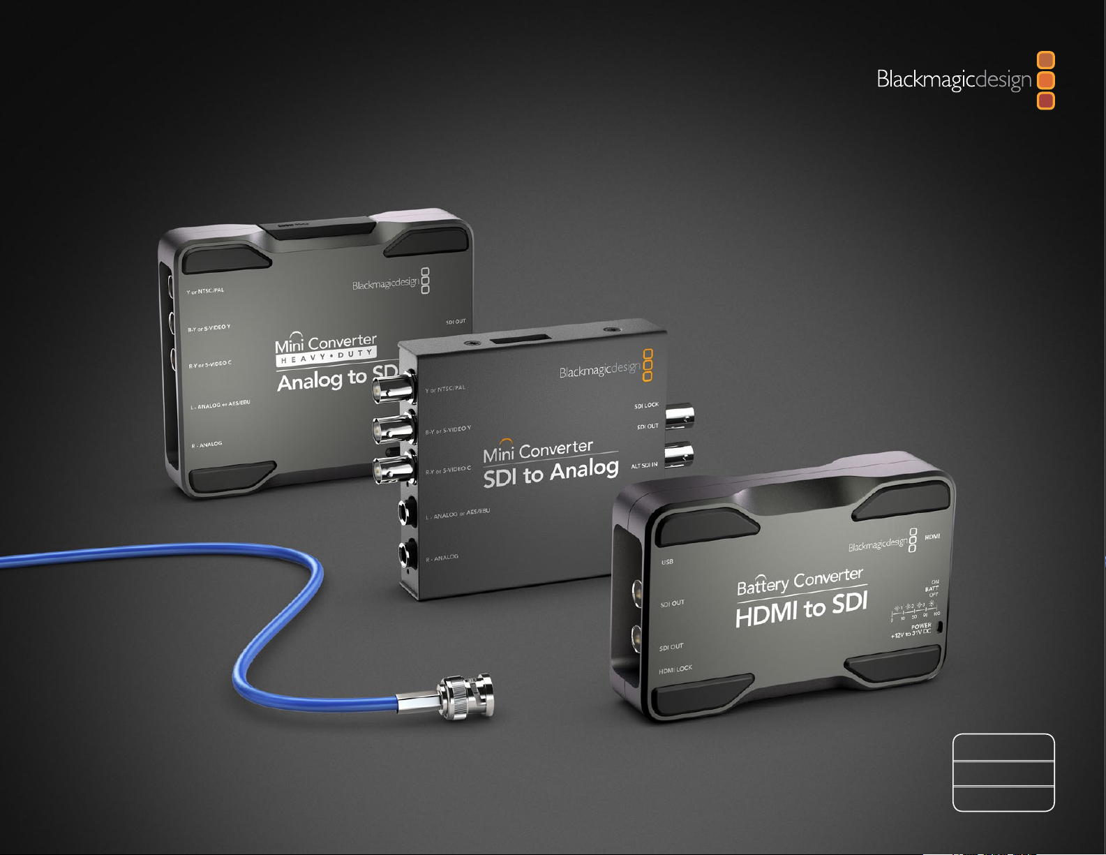
Blackmagic Converters are available in 3 designs. Mini Converter, Mini Converter Heavy Duty and Battery
Converter.
Mini Converter is a sturdy and lightweight design.
Mini Converter
Mini Converter Heavy Duty
Battery Converter
Mini Converter Heavy Duty is robust, ultra strong, and capable of withstanding the harshest
environments.
Battery Converter is ultra strong with an internal rechargeable battery for operating in the field
without external power.
Simple mini switches select input and output settings. The mini switch legend printed on the back of your
converter provides all the information you need.
A 12V power supply is included with international socket adapters. Specified models can also be battery
operated using your own 12 - 31 V DC power supply and software updates are installed via the converter's
USB port. Blackmagic Converters provide the following conversions:
Conversion Mini Converter Mini Converter Heavy Duty Battery Converter
SDI to Analog • •
Analog to SDI • •
HDMI to SDI • • •
SDI to HDMI • • •
SDI to HDMI 4K •
SDI to Audio •
Audio to SDI •
Optical Fiber •
Optical Fiber 4K •
UpDownCross •
Sync Generator •
SDI Distribution •
SDI Multiplex 4K •
Page 5
5
Getting Started
Locking the power cable to the converter’s cable tie point
prevents accidental disconnection.
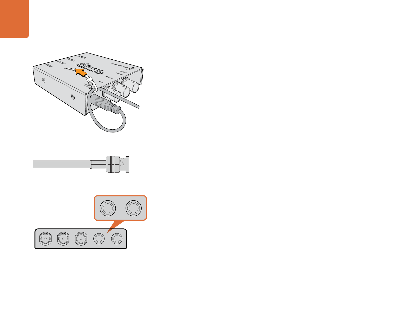
BNC connectors carry SDI video signals with embedded audio.
Plugging in Power
Plug in the 12 volt power supply using the socket adapter for your country. The cable tie point is for securing
the power connection to your converter.
If you are using a Battery Converter with access to external power, we recommend using external power
unless you need to use the built in battery. This will maximize the life of the battery and ensure your Battery
Converter is fully charged when you need it.
Plugging in Video
Plug your source video into your converter's video input and plug the video output into your destination
equipment. Third party adapters are commonly available to connect any video equipment using alternative
connectors such as RCA.
The next step is to plug in audio.
Plugging in Audio
If you're using embedded audio in SDI, optical fiber SDI or HDMI, audio is already connected via the video
input. If using external analog or digital audio, plug into your converter's TRS audio inputs or outputs. Third
party adapters are commonly available to connect any audio equipment using alternative connectors such
as XLR.
Connect external analog or digital audio to your converter's TRS
audio connectors.
Now configure any required settings using the mini switches.
Page 6
6
1ON2 3 4 5 6 7 8
Getting Started
1ON2 3 4 5 6 7 8
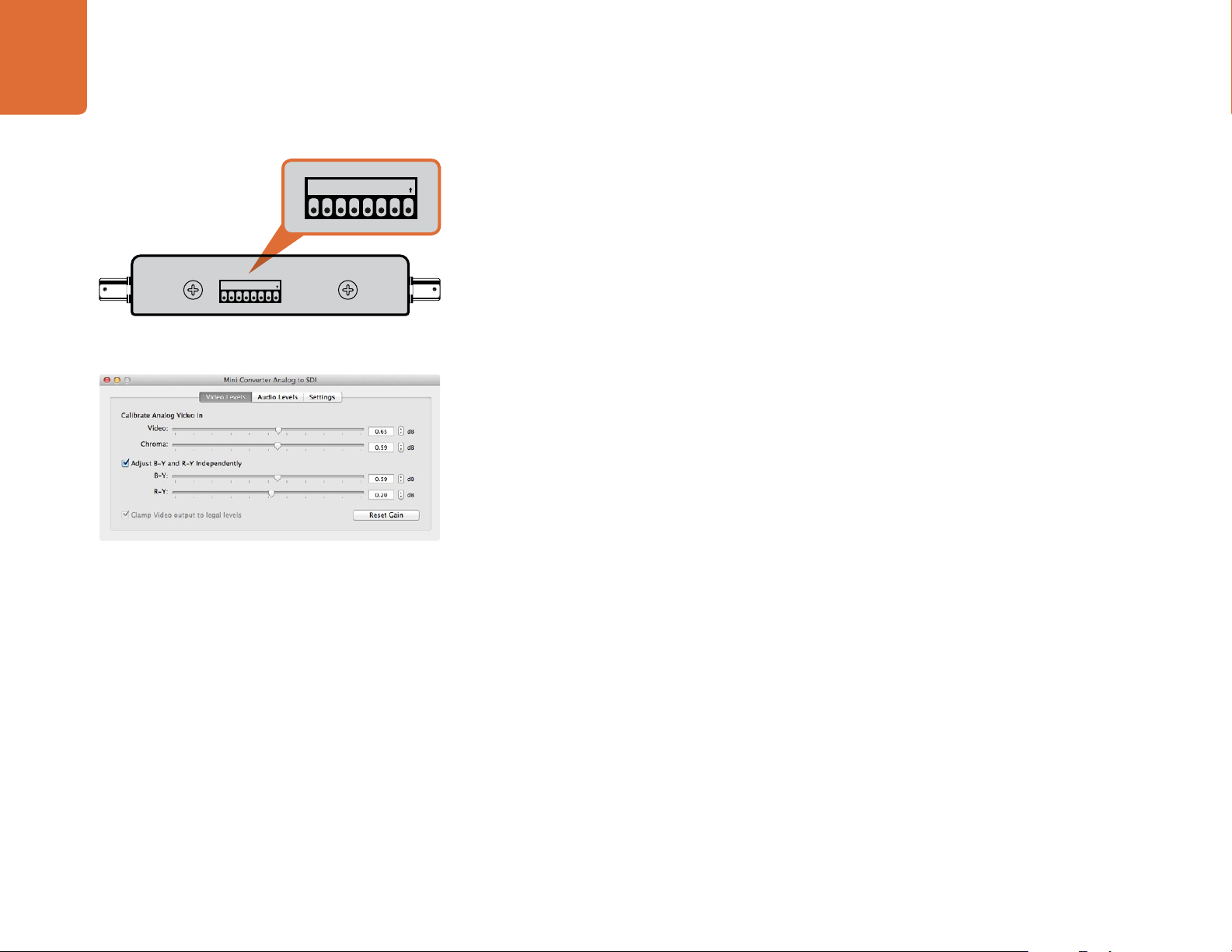
Internal settings are applied by adjusting mini switches with a pen.
Blackmagic Converter Utility lets you adjust analog video levels,
audio levels and conversion settings.
Applying Settings using Mini Switches
Many models of Mini Converter and Mini Converter Heavy Duty have mini switches used to configure
internal settings. Change your settings using the tip of a pen.
On models with mini switches, you'll find a switch settings diagram printed on their base. Ensure your switch
settings correspond to the legend by observing the mini switch numbers from 8 to 1, left to right. The
numbers on the switches will appear upside down.
For a comprehensive description of the mini switches and their settings, refer to your converter model in
this manual.
Applying Settings using Blackmagic Converter Utility
Similar to mini switches, the included Converter Utility software for Mac OS X and Windows provides
adjustment settings.
The Converter Utility interface is composed of three panes for Video Levels, Audio Levels and Settings.
Settings not relevant to your converter model will be grayed out and inactive.
Analog video and audio levels, plus AES/EBU audio levels can be adjusted. Any adjustments will
immediately be saved to your Blackmagic Converter. This means that if power is lost, the new settings will
be re-established as soon as power is restored.
Page 7
7
Mini Converter SDI to Analog
Mini Converter SDI to Analog
1
2
3
4
5
6
Convert from SD/HD-SDI to analog component, NTSC and PAL video out, plus balanced AES/EBU and
analog audio out. Your converter easily connects to analog video monitors and decks such as Betacam SP
7
8
9
and VHS. A hardware down converter lets you connect HD-SDI video to SD analog equipment. You can
even output pairs of analog audio from 16 de-embedded SDI audio channels.
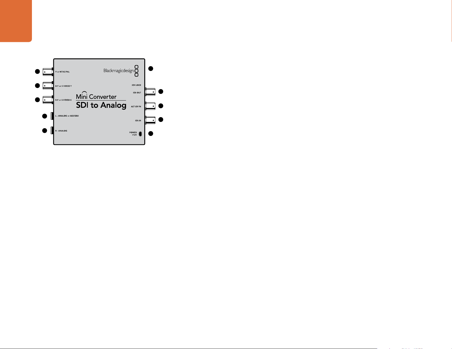
Connectors
1. Y or NTSC/PAL
Analog component Y, or composite NTSC/PAL output on a BNC connector.
10
2. B-Y or S-VIDEO Y
Analog component B-Y, or S-Video Y output BNC connector.
3. R-Y or S-VIDEO C
Analog component R-Y, or S-Video C output BNC connector.
4. L - ANALOG or AES/EBU
Balanced left channel analog audio, or AES/EBU digital audio output on a 1/4" TRS connector.
5. R - ANALOG
Balanced right channel analog audio output 1/4" TRS connector.
6. MINI-B USB PORT
Connects to the Converter Utility software via your Mac OS X or Windows computer. The Mini Converter’s
internal software is also updated using the USB port.
Blackmagic Mini Converter SDI to Analog
7. SDI OUT
SDI video output on a BNC connector.
8. ALT SDI IN
Redundant SDI input is provided as an optional back up.
9. SDI IN
Primary SDI input.
10. POWER +12V
12 volt power supply input.
Page 8
8
Mini Converter SDI to Analog
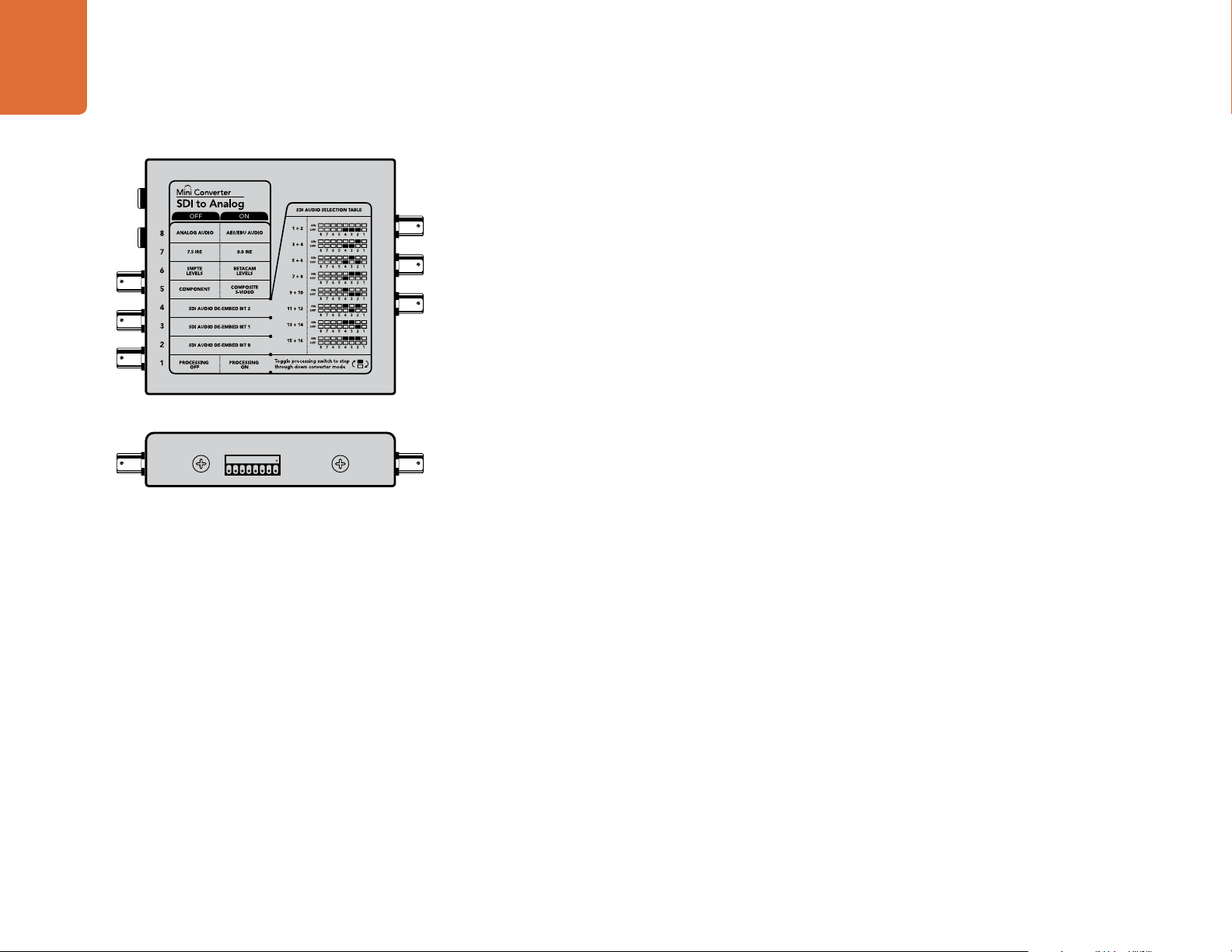
Mini Switches
Mini Converter SDI to Analog’s mini switches provide the following settings:
Switch 8 - Analog Audio, AES/EBU Audio
Set switch 8 to OFF to select balanced analog audio, or to ON for digital AES/EBU audio output.
Switch 7 - 7.5 IRE - 0.0 IRE
The USA and countries using NTSC with 7.5 setup should set switch 7 to OFF. If you’re working in countries
not using 7.5 setup, set switch 7 to ON. This setting only affects composite or S-Video outputs.
Switch 6 - SMPTE Levels - Betacam Levels
Set switch 6 to OFF for SMPTE levels, or ON for Betacam levels. SMPTE levels are more common and even
Betacam SP decks can use SMPTE levels, so only switch this to Betacam if you are sure that Betacam levels
are being used.
1ON2 3 4 5 6 7 8
Change your converter's internal settings by adjusting the mini
switches using the tip of a pen.
Switch 5 - Component, Composite or S-Video
Set switch 5 to OFF to select analog component video output, or ON for composite and S-Video outputs.
To display the HD video input on the S-Video and composite outputs, down conversion must be set to ON.
Component analog video supports both HD and SD video.
Switch 4 - SDI Audio De-Embed Bit 2
Switches 4, 3 and 2 are grouped together to provide 8 ON/OFF combinations. Having eight different
combinations allows eight independent pairs of audio channels to be de-embedded from your SDI input.
Switch 3 - SDI Audio De-Embed Bit 1
See switch 4 description.
Switch 2 - SDI Audio De-Embed Bit 0
See switch 4 description.
Switch 1 - Processing Off - Processing On
Down convert HD to SD with 3 types of aspect ratios by cycling through switch 1. For example, each time
you cycle between Off and On you apply anamorphic, center cut or letterbox aspect ratios. Leaving switch
1 set to OFF bypasses the down converter and outputs in HD.
When connected to the Blackmagic Converter Utility via USB, your down conversion settings are controlled
by the software. If you want the converter to remember your software settings, disconnect from the
computer, power cycle your converter and set your down conversion using mini switch 1.
Page 9
9
Mini Converter SDI to Analog
Mini Switch Settings Example:
Experiment with the mini switches by setting your Blackmagic Mini Converter to output high definition
component video and analog audio channels 1 and 2 by setting switches 8, 5, 4, 3 and 2 to the OFF position
SDI Audio Selection Table
Audio Channels Switch 4 Switch 3 Switch 2 Switch Diagram
1 and 2 OFF OFF OFF
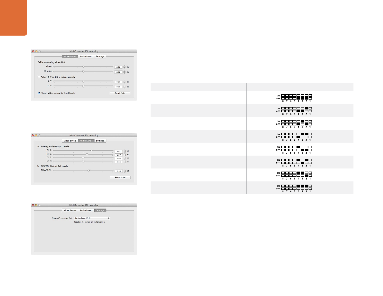
Adjust analog video levels using Blackmagic Converter Utility.
The Clamp Video output to legal levels setting is checked
by default. This setting ensures your analog output is a true
representation of the SDI input. Adjusting video levels may result
in illegal colors.
Adjust audio levels using Blackmagic Converter Utility.
3 and 4 OFF OFF ON
5 and 6 OFF ON OFF
7 and 8 OFF ON ON
9 and 10 ON OFF OFF
11 and 12 ON OFF ON
13 and 14 ON ON OFF
15 and 16 ON ON ON
Blackmagic Converter Utility Settings
The Converter Utility software complements your mini switch settings by providing supplementary
adjustment options.
The Video Levels pane lets you adjust the analog video luminance and chroma levels, and the B-Y and R-Y
component chroma levels independently.
The Audio Levels pane lets you adjust audio levels for your selected analog channels or AES/EBU audio
reference levels.
Adjust down conversion settings using Blackmagic Converter
Utility.
The Settings pane lets you select down conversion aspect ratio options. When your converter is not
connected to Converter Utility software, the mini switches take priority. You will need to set mini switch 1 if
you want to retain your aspect ratio settings after disconnecting from the Converter Utility software.
Page 10
10
Mini Converter SDI to Analog
.
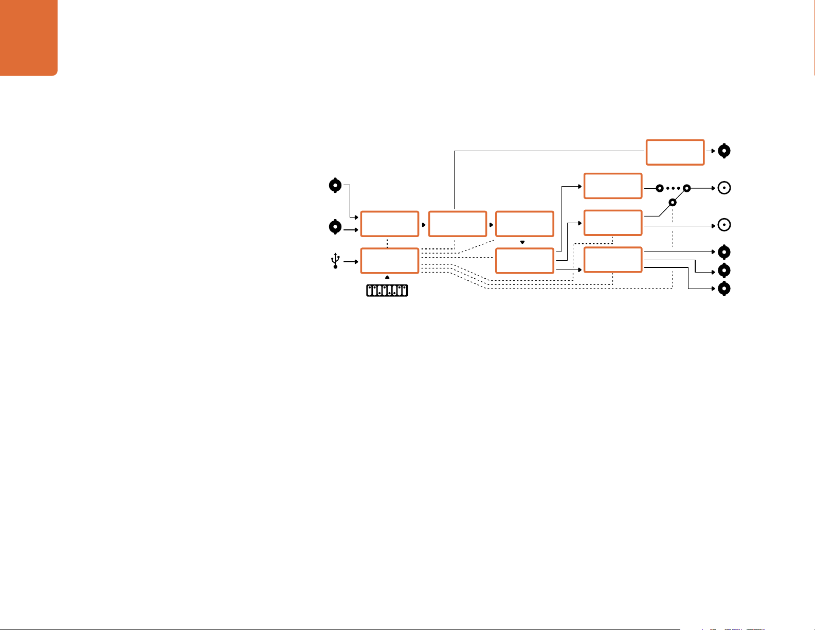
Mini Converter SDI to Analog Block Diagram
SDI In
Alt SDI In
USB
Input automatically
detects between SD,
HD-SDI and 3Gb/s SDI
Redundant
Input Automatic
Change Over
Central
Processor and
Firmware
Mini Switches
Equalizer,
Re-Clocker and
10 bit De-Serializer
10 bit HD to
SD Down
Converter
SDI Audio
De-Embedder
AES/EBU
Audio Formatter
Audio Digital to
Analog with
Balanced Output
12 Bit Digital to
Analog SD/HD
Video Converter
Component output can switch
Automatic SDI/
HD-SDI/3G HD-
SDI Cable Driver
Analog or AES/EBU
Audio Out Switch
to S-Video and composite
Loop SDI
Out
Left Analog Out
or AES/EBU Out
Right Analog Out
Y
R-Y
B-Y
Page 11
Mini Converter Analog to SDI
11
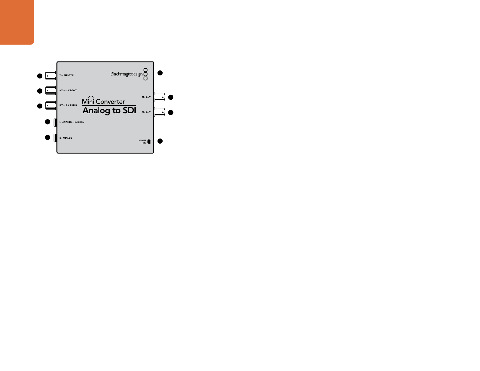
Mini Converter Analog to SDI
1
2
3
4
5
6
7
8
9
Blackmagic Mini Converter Analog to SDI
Convert video and audio from analog equipment such as Betacam SP decks, HDV cameras and game
consoles to SD/HD-SDI video. A choice of analog and digital formats is supported, including component
SD/HD, S-Video, or composite NTSC and PAL. The converter’s HD-SDI outputs include the option to
embed digital AES/EBU or analog audio.
Connectors
1. Y or NTSC/PAL
Analog component Y, or composite NTSC/PAL input on a BNC connector.
2. B-Y or S-VIDEO Y
Analog component B-Y, or S-Video Y input BNC connector.
3. R-Y or S-VIDEO C
Analog component R-Y, or S-Video C input BNC connector.
4. L - ANALOG or AES/EBU
Balanced left channel analog audio, or AES/EBU digital audio input on a 1/4" TRS connector.
5. R - ANALOG
Balanced right channel analog audio input 1/4" TRS connector.
6. MINI-B USB PORT
Connects to the Converter Utility software via your Mac OS X or Windows computer. The Mini Converter’s
internal software is also updated using the USB port.
7. SDI OUT
SDI video output on a BNC connector.
8. SDI OUT
Secondary SDI output.
9. POWER +12V
12 volt power supply input.
Page 12
12
Mini Converter Analog to SDI
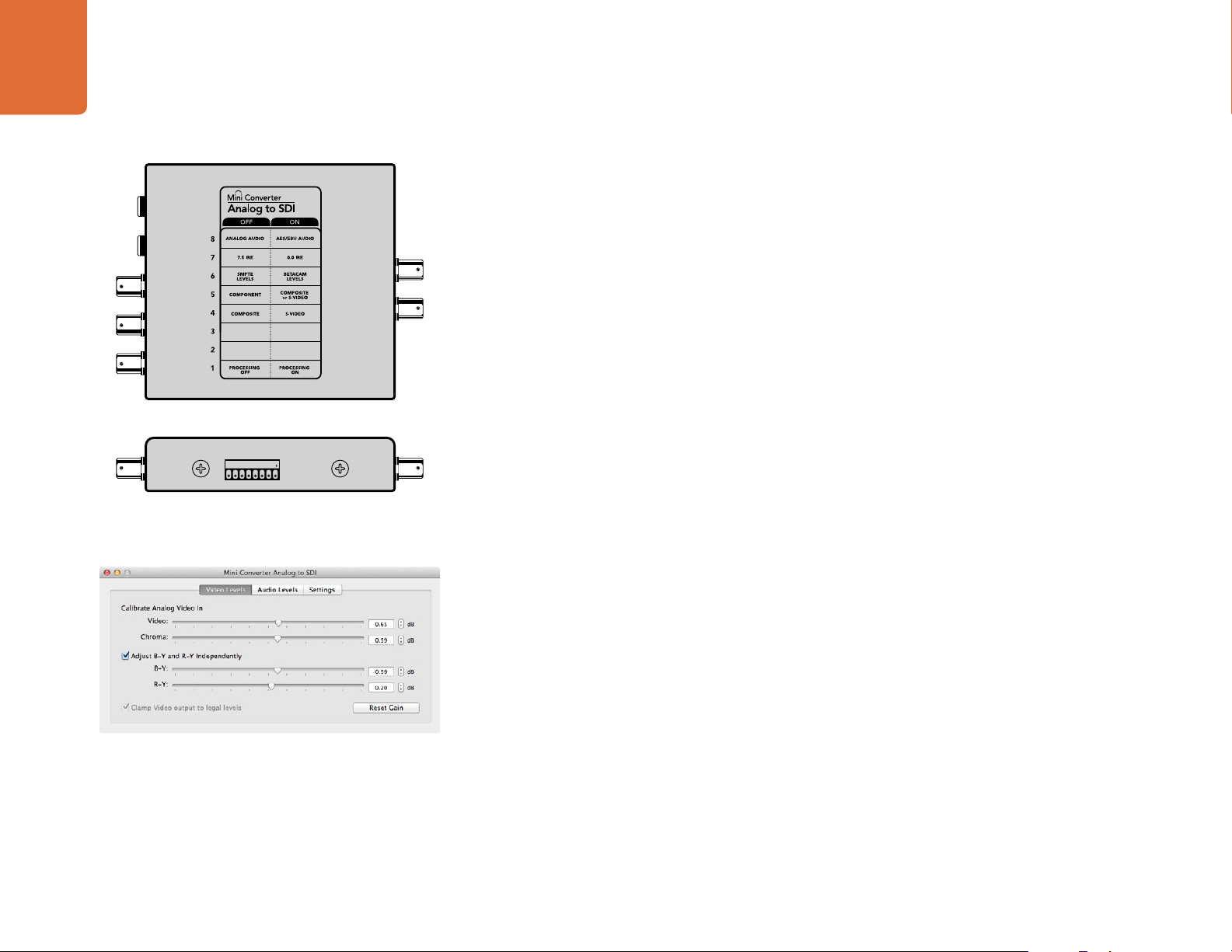
Mini Switches
Mini Converter Analog to SDI’s mini switches provide the following settings:
Switch 8 - Analog Audio, AES/EBU Audio
Set switch 8 to OFF to select balanced analog audio, or to ON for digital AES/EBU audio input.
Switch 7 - 7.5 IRE - 0.0 IRE
The USA and countries using NTSC with 7.5 setup should set switch 7 to OFF. If you’re working in countries
not using 7.5 setup, set switch 7 to ON. This setting only affects composite or S-Video outputs.
Switch 6 - SMPTE Levels - Betacam Levels
This setting selects between SMPTE or Betacam video levels. Set switch 6 to OFF for SMPTE levels, or to
ON for Betacam levels. SMPTE levels are more common and even Betacam SP decks can use SMPTE levels
so only switch this to Betacam if you are sure that Betacam levels are being used.
1ON2 3 4 5 6 7 8
Change your converter's internal settings by adjusting the mini
switches using the tip of a pen.
Adjust analog video levels using Blackmagic Converter Utility.
Switch 5 - Component, Composite or S-Video
Set switch 5 to OFF to select analog component video input, or to ON for composite video and S-Video
analog inputs.
Switch 4 - Composite - S-Video
Set switch 4 to OFF to select composite video input, or to ON for S-Video input.
Switch 1 - Processing Off - Processing On
This switch is not used.
Mini Switch Settings Example: Experiment with the mini switches by setting your Blackmagic Mini
Converter to Component Video and Analog Audio output by setting switches 8 and 5 to the OFF position.
Blackmagic Converter Utility Settings
The Converter Utility software complements your mini switch settings by providing supplementary
adjustment options.
The Video Levels pane lets you adjust the analog video luminance and chroma levels, and the B-Y and R-Y
component chroma levels independently.
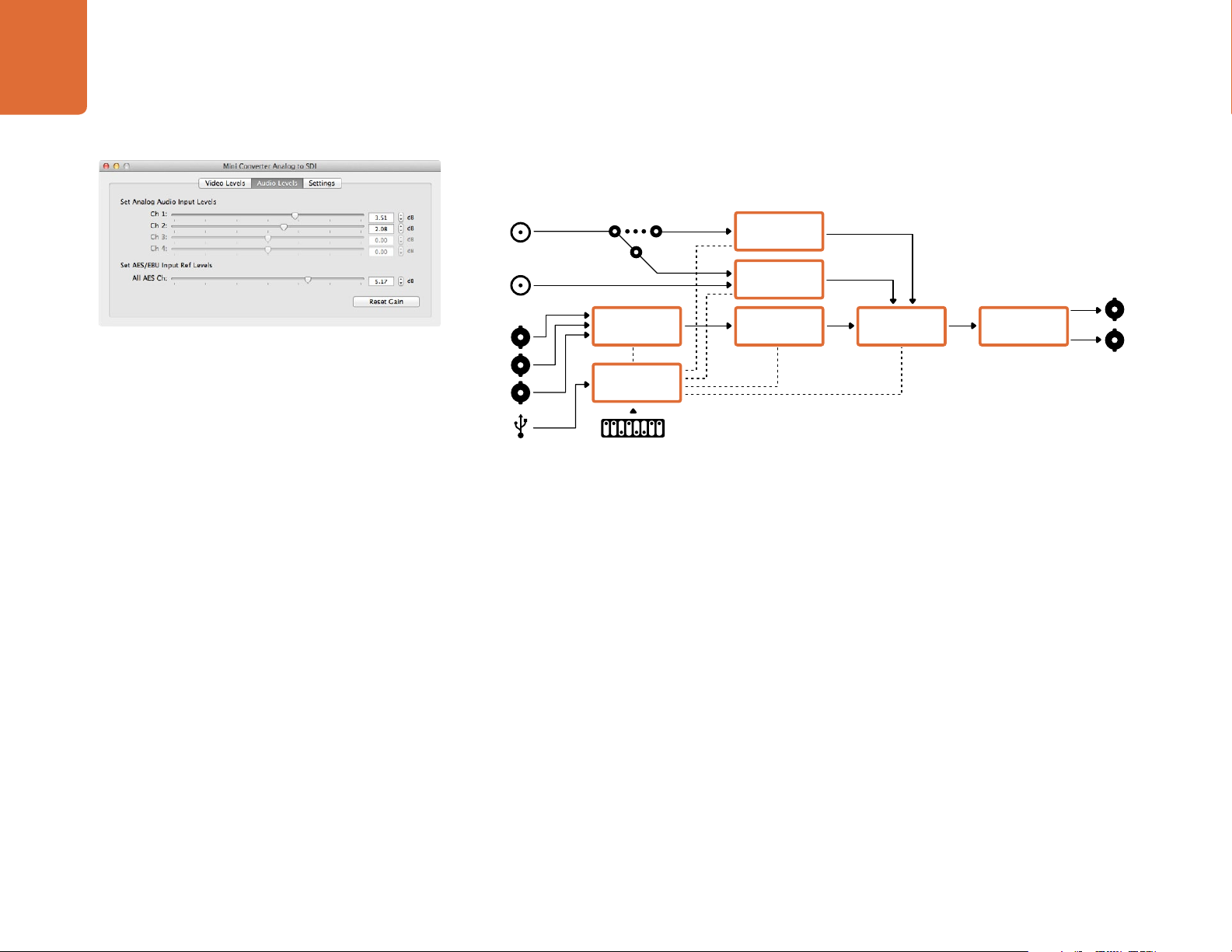
The Audio Levels pane lets you adjust audio levels for analog channels or AES/EBU reference levels.
Page 13
13
Mini Converter Analog to SDI
Mini Converter Analog to SDI Block Diagram
Left Analog In
or AES/EBU
Right Analog In
Adjust audio levels using Blackmagic Converter Utility.
Y
R-Y
B-Y
USB
Analog or AES/EBU
Audio Switch
12 bit Digital to
Analog SD/HD
Video Converter
Central
Processor and
Firmware
Mini Switches
AES/EBU
Sample Rate
Converter
Audio Analog to
Digital from
Balanced Input
Customizable
Video Processor
Component input can switch to
S-Video and Composite
SDI Audio
Embedder
Automatic SDI/
HD-SDI/3G HD-
SDI Cable Driver
SDI Out
SDI Out
Page 14
Mini Converter SDI to HDMI
14
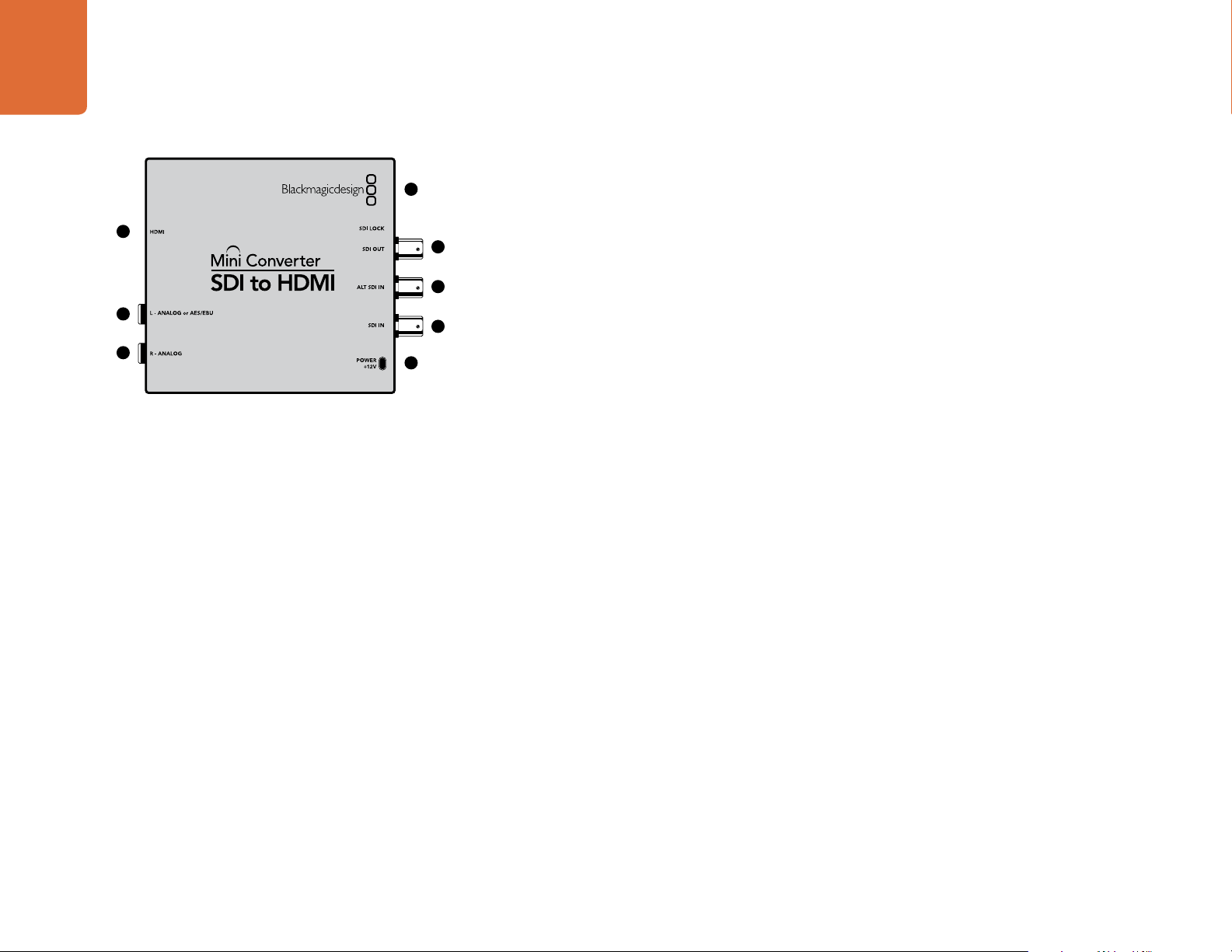
Mini Converter SDI to HDMI
Blackmagic Mini Converter SDI to HDMI
4
1
2
3
5
6
7
8
Connect a huge range of HDMI displays and video projectors to SDI based equipment. Your Mini Converter
SDI to HDMI automatically detects between SD/HD/3G-SDI and converts to HDMI with embedded audio,
plus balanced AES/EBU or analog audio out.
Connectors
1. HDMI
HDMI type A video output.
2. L - ANALOG or AES/EBU
Balanced left channel analog audio, or AES/EBU digital audio output on a 1/4" TRS connector.
3. R - ANALOG
Balanced right channel analog audio output 1/4" TRS connector.
4. MINI-B USB PORT
Connects to the Converter Utility software via your Mac OS X or Windows computer. The Mini Converter’s
internal software is also updated using the USB port.
5. SDI OUT
SDI video output on a BNC connector.
6. ALT SDI IN
Redundant SDI input is provided as an optional back up.
7. SDI IN
Primary SDI input.
8. POWER +12V
12 volt power supply input.
Page 15
15
Mini Converter SDI to HDMI
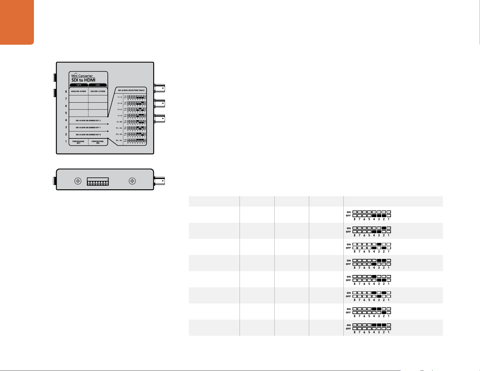
Mini Switches
Mini Converter SDI to HDMI’s mini switches provide the following settings:
Switch 8 - Analog Audio, AES/EBU Audio
Set switch 8 to OFF to select balanced analog audio, or to ON for digital AES/EBU audio output.
Switch 4 - SDI Audio De-Embed Bit 2
Switches 4, 3 and 2 are grouped together to provide 8 ON/OFF combinations. Having eight different
combinations allows eight independent pairs of audio channels to be de-embedded from your SDI input
and output to HDMI, analog or AES/EBU audio.
Switch 3 - SDI Audio De-Embed Bit 1
See switch 4 description.
Switch 2 - SDI Audio De-Embed Bit 0
1ON2 3 4 5 6 7 8
Change your converter's internal settings by adjusting the mini
switches using the tip of a pen.
See switch 4 description.
SDI Audio Selection Table
Audio Channels Switch 4 Switch 3 Switch 2 Switch Diagram
1 and 2 OFF OFF OFF
3 and 4 OFF OFF ON
5 and 6 OFF ON OFF
7 and 8 OFF ON ON
9 and 10 ON OFF OFF
11 and 12 ON OFF ON
13 and 14 ON ON OFF
15 and 16 ON ON ON
Page 16
16
Mini Converter SDI to HDMI
SDI Audio Selection Table
Switch 1 - Processing Off - Processing On
This switch is not used.
Mini Switch Settings Example: Experiment with the mini switches by setting your Blackmagic Mini
Converter to de-embed SDI audio channels 1 and 2 and output to analog by setting switches 8, 4, 3 and 2
to the OFF position.
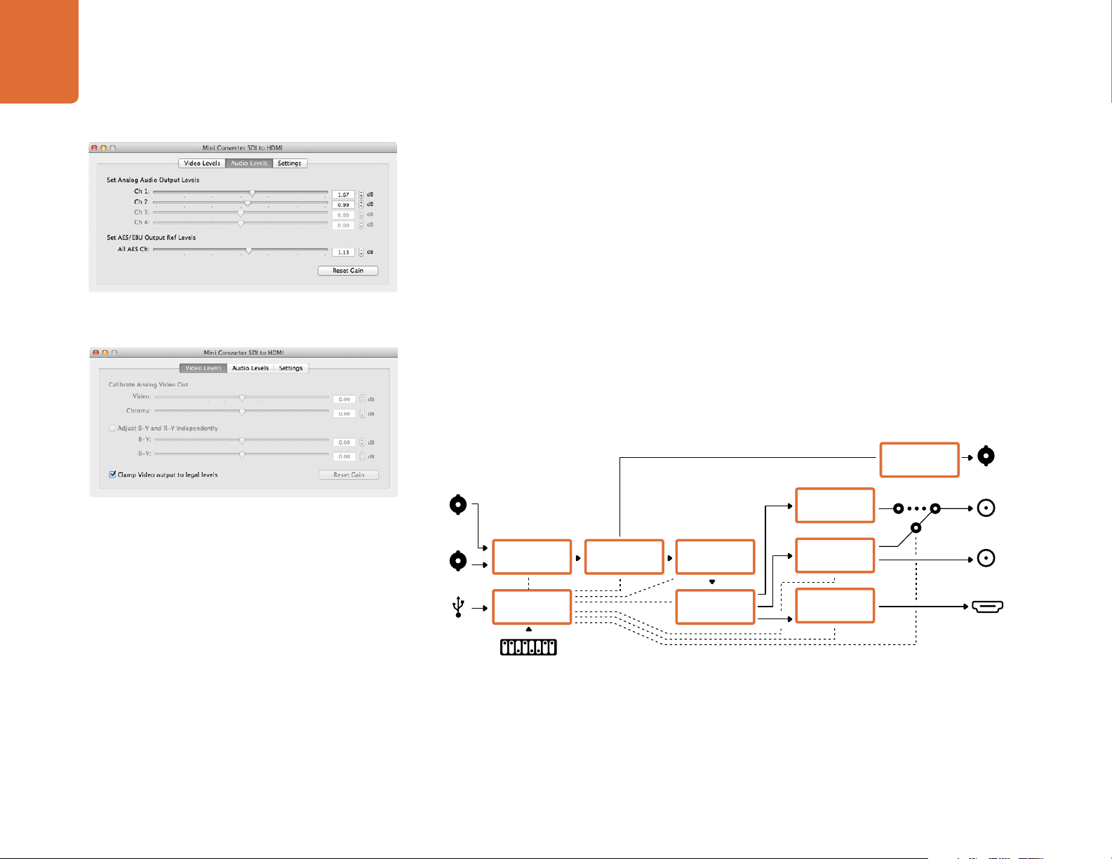
Blackmagic Converter Utility Settings
Adjust audio levels using Blackmagic Converter Utility.
The Clamp Video output to legal levels setting is checked
by default. This setting ensures your analog output is a true
representation of the SDI input. Adjusting video levels may result
in illegal colors.
The Converter Utility software complements your mini switch settings by providing supplementary
adjustment options.
The Audio Levels pane lets you adjust audio levels for the selected analog channels or AES/EBU
reference levels.
Mini Converter SDI to HDMI Block Diagram
SDI In
Alt SDI In
USB
Input automatically
detects between SD,
HD-SDI and 3G-SDI
Redundant
Input Automatic
Change Over
Central
Processor and
Firmware
Equalizer,
Re-Clocker and
10 bit De-Serializer
Customizable
Video Processor
SDI Audio
De-Embedder
AES/EBU
Audio Formatter
Audio Digital to
Analog with
Balanced Output
HDMI Video and
Audio Formatter
Automatic SDI/
HD-SDI/3G HD-
SDI Cable Driver
Analog or AES/EBU
Audio Out Switch
Loop SDI
Out
Left Analog Out
or AES/EBU Out
Right Analog Out
HDMI Out
Mini Switches
Page 17
Mini Converter HDMI to SDI
17
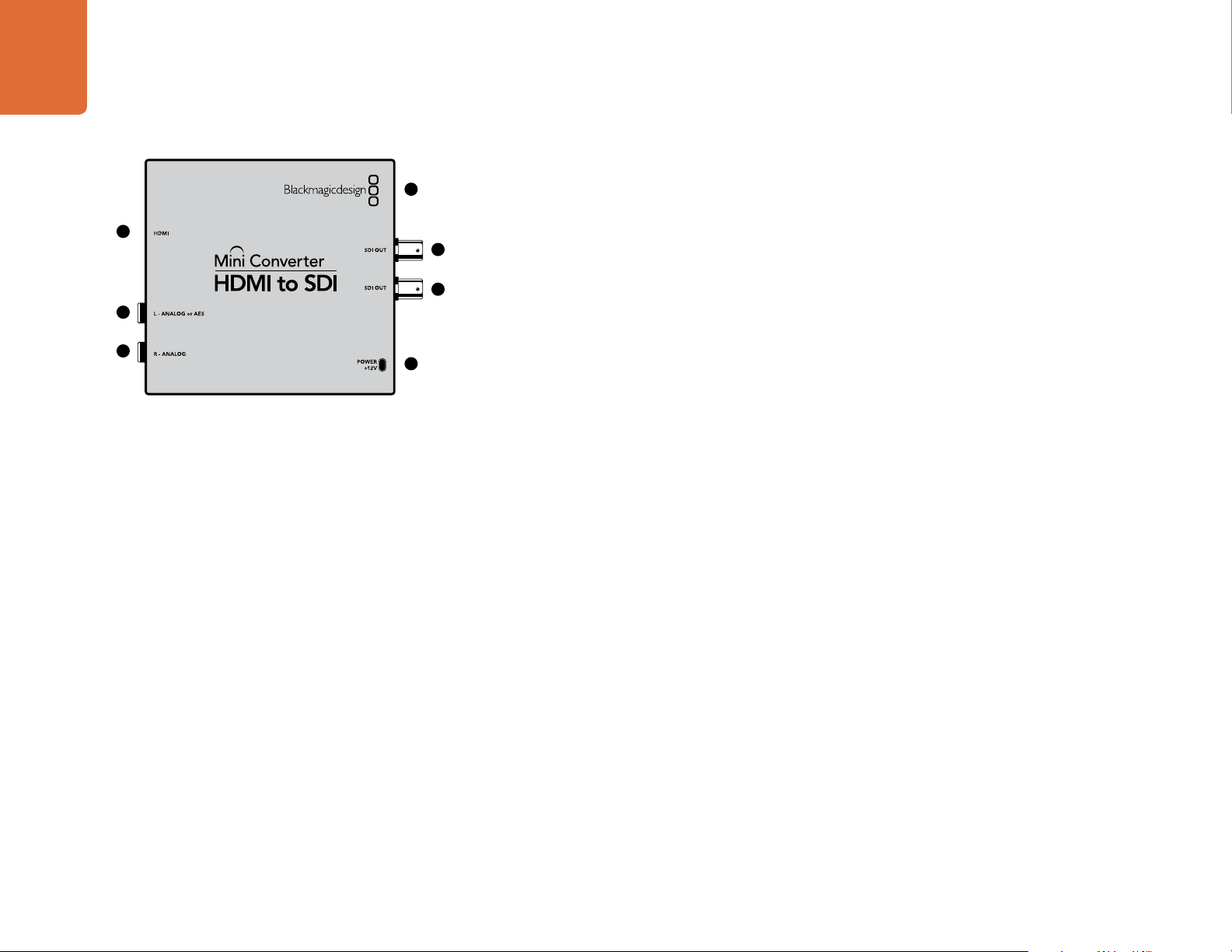
Mini Converter HDMI to SDI
Blackmagic Mini Converter HDMI to SDI
4
1
5
6
2
3
7
Convert HDMI outputs from devices such as HDV cameras and game consoles to SDI with the choice to
embed audio from HDMI, AES/EBU or balanced analog audio inputs. This means you can send video
signals from HDMI over SDI using the longest SDI cables. You can even add SDI outputs to computers with
HDMI compatibility. This converter also includes HD to SD down conversion.
Connectors
1. HDMI
HDMI type A video input.
2. L - ANALOG or AES/EBU
Balanced left channel analog audio or AES/EBU digital audio input on a 1/4" TRS connector.
3. R - ANALOG
Balanced right channel analog audio output 1/4" TRS connector.
4. MINI-B USB PORT
Connects to the Converter Utility software via your Mac OS X or Windows computer. The Mini Converter’s
internal software is also updated using the USB port.
5. SDI OUT
SDI video output on a BNC connector.
6. SDI OUT
Secondary SDI output.
7. POWER +12V
12 volt power supply input.
Page 18
18
Mini Converter HDMI to SDI
Mini Switches
Mini Converter HDMI to SDI’s mini switches provide the following settings:
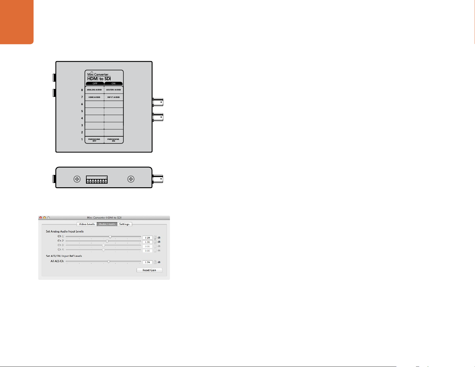
Switch 8 - Analog Audio, AES/EBU Audio
Set switch 8 to OFF to select balanced analog audio, or to ON for digital AES/EBU audio input. To use these
inputs Switch 7 must also be set to ON.
Switch 7 - HDMI Audio - Input Audio
Set switch 7 to OFF to select embedded HDMI audio, or to ON for analog or AES/EBU audio.
Switch 1 - Processing Off - Processing On
Down convert HD to SD with 3 types of aspect ratios by cycling through switch 1. For example, each time
you cycle between OFF and On you apply anamorphic, center cut or letterbox aspect ratios. Leaving switch
1 set to OFF bypasses the down converter and outputs in HD.
1ON2 3 4 5 6 7 8
Change your converter's internal settings by adjusting the mini
switches using the tip of a pen.
Converter Utility can be used to adjust audio levels.
When connected to the Blackmagic Converter Utility via USB, your down conversion settings are controlled
by the software. If you want the converter to remember your software settings, disconnect from the
computer, power cycle your converter and set your down conversion using mini switch 1.
Blackmagic Converter Utility Settings
The Converter Utility software complements your mini switch settings by providing supplementary
adjustment options.
The Audio Levels pane lets you adjust audio levels for analog channels or AES/EBU audio reference levels.
Page 19
19
Mini Converter HDMI to SDI
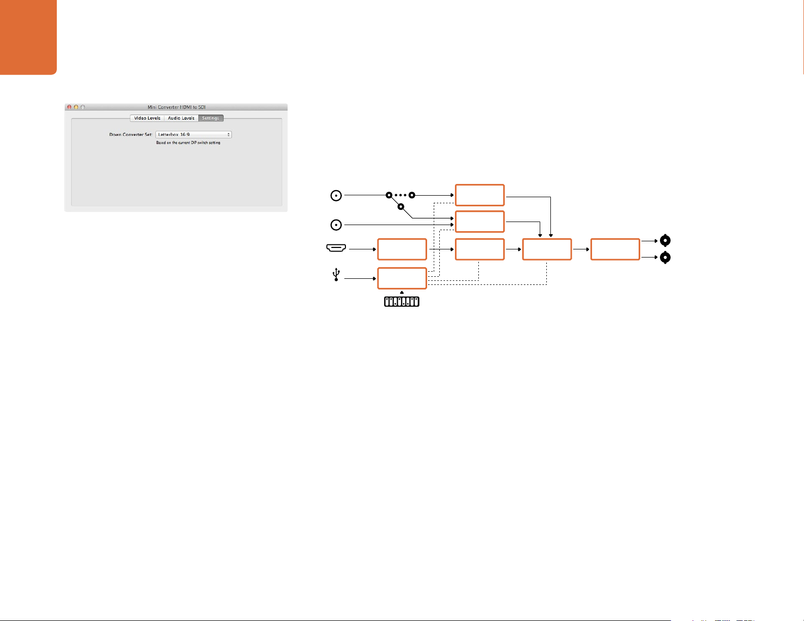
The Settings pane lets you select down conversion aspect ratio options. However, your settings will need
to be set by mini switch 1 if you want to retain them after disconnecting your converter from the Converter
Utility software.
Mini Converter HDMI to SDI Block Diagram
Left Analog In
or AES/EBU
Adjust down conversion settings using Blackmagic Converter
Utility.
Right Analog In
HDMI In
USB
Analog or AES/EBU
Audio Switch
HDMI Video and
Audio Decoder
Central
Processor and
Firmware
Mini Switches
AES/EBU
Sample Rate
Converter
Audio Analog to
Digital with
Balanced Input
Customizable
Video Processor
SDI Audio
Embedder
Automatic SDI/
HD-SDI/3G HD-
SDI Cable Driver
SDI Out
SDI Out
Page 20

Mini Converter SDI to Audio
20
Mini Converter SDI to Audio
Blackmagic Mini Converter SDI to Audio
5
1
6
2
7
3
8
4
9
De-embed 4 channels of audio from any SDI video connection and output to 4 channels of analog audio
or 8 channels of AES/EBU digital. Output to audio equipment such as audio mixers, analog decks and
reference monitors. Additional SDI audio channels can be de-embedded by daisy chaining another Mini
Converter SDI to Audio to your converter's SDI output.
Connectors
1. CH 1 ANALOG or CH 1 & 2 AES/EBU
Balanced analog audio channel 1, or AES/EBU digital audio channels 1 and 2 output on a 1/4" TRS connector.
2. CH 2 ANALOG or CH 3 & 4 AES/EBU
Balanced analog audio channel 2, or AES/EBU digital audio channels 3 and 4 output 1/4" TRS connector.
3. CH 3 ANALOG or CH 5 & 6 AES/EBU
Balanced analog audio channel 3, or AES/EBU digital audio channels 5 and 6 output 1/4" TRS connector.
4. CH 4 ANALOG or CH 7 & 8 AES/EBU
Balanced analog audio channel 4, or AES/EBU digital audio channels 7 and 8 output 1/4" TRS connector.
5. MINI-B USB PORT
Connects to the Converter Utility software via your Mac OS X or Windows computer. The Mini Converter’s
internal software is also updated using the USB port.
6. SDI OUT
Loop through SDI video output on a BNC connector.
7. ALT SDI IN
Redundant SDI input provided as an optional back up.
8. SDI IN
Primary SDI input.
9. POWER +12V
12 volt power supply input.
Page 21

21
Mini Converter SDI to Audio
Mini Switches
Mini Converter SDI to Audio’s mini switches provide the following settings:
Switch 8 - Analog Audio, AES/EBU Audio
Set switch 8 to OFF to select balanced analog audio, or to ON for digital AES/EBU audio output.
Switch 6 - Audio Group Bit 1
Switches 6 and 5 are grouped together to provide four ON/OFF combinations. This allows up to 4
quadruplets of analog audio channels, or 2 sets of 8 AES/EBU audio channels, to be de-embedded from
your SDI input.
Audio Selection Tables
1ON2 3 4 5 6 7 8
Change your converter's internal settings by adjusting the mini
switches using the tip of a pen.
Analog Audio
Channels
1 to 4 OFF OFF
5 to 8 OFF ON
9 to 12 ON OFF
13 to 16 ON ON
AES/EBU Channels Switch 6 Switch 5 Switch Diagram
1 to 8 OFF OFF
9 to 16 OFF ON
Switch 5 - Audio Group Bit 0
See switch 6 description.
Mini Switch Settings Example: Try experimenting with the mini switches. Select analog audio channels 1
to 4 by setting switches 8, 6 and 5 to the OFF position.
Switch 6 Switch 5 Switch Diagram
Page 22

22
Mini Converter SDI to Audio
Blackmagic Converter Utility Settings
The Converter Utility software complements your mini switch settings by providing additional adjustment
options.
The Audio Levels pane lets you adjust audio levels for the selected analog channels or AES/EBU audio
reference levels.
Mini Converter SDI to Audio Block Diagram
Adjust audio levels using Blackmagic Converter Utility.
SDI In
Alt SDI In
USB
Input automatically
detects between SD,
HD-SDI and 3G-SDI
Redundant
Input Automatic
Change Over
Central
Processor and
Firmware
Mini Switches
Equalizer,
Re-Clocker and
10 bit De-Serializer
SDI Audio
De-Embedder
AES/EBU
Audio Formatter
Audio Digital to
Analog with
Balanced Output
AES/EBU
Audio Formatter
AES/EBU
Audio Formatter
Audio Digital to
Analog with
Balanced Output
AES/EBU
Audio Formatter
Automatic SDI/
HD-SDI/3G HD-
SDI Cable Driver
Analog or AES/EBU
Analog or AES/EBU
Analog or AES/EBU
Analog or AES/EBU
Loop SDI Out
Ch 1 Analog or
Ch 1&2 AES/EBU
Ch 2 Analog or
Ch 3&4 AES/EBU
Ch 3 Analog or
Ch 5&6 AES/EBU
Ch 4 Analog or
Ch 7&8 AES/EBU
Page 23

Mini Converter Audio to SDI
23
Mini Converter Audio to SDI
Blackmagic Mini Converter Audio to SDI
5
1
6
2
7
3
8
4
9
Embed four channels of analog audio, or eight channels of AES/EBU digital audio into any SDI video
connection. You can use this Mini Converter to embed audio from equipment, such as audio mixers and
analog decks, into SDI video connections for use with SDI routers and decks. Additional SDI audio channels
can be embedded by daisy chaining another Mini Converter Audio to SDI to your converter's SDI output.
Connectors
1. CH 1 ANALOG or CH 1 & 2 AES/EBU
Balanced analog audio channel 1, or AES/EBU digital audio channels 1 and 2 input on a 1/4" TRS connector.
2. CH 2 ANALOG or CH 3 & 4 AES/EBU
Balanced analog audio channel 2, or AES/EBU digital audio channels 3 and 4 input 1/4" TRS connector.
3. CH 3 ANALOG or CH 5 & 6 AES/EBU
Balanced analog audio channel 3, or AES/EBU digital audio channels 5 and 6 input 1/4" TRS connector.
4. CH 4 ANALOG or CH 7 & 8 AES/EBU
Balanced analog audio channel 4, or AES/EBU digital audio channels 7 and 8 input 1/4" TRS connector.
5. MINI-B USB PORT
Connects to the Converter Utility software via your Mac OS X or Windows computer. The Mini Converter’s
internal software is also updated using the USB port.
6. SDI OUT
Loop through SDI video output on a BNC connector.
7. ALT SDI IN
Redundant SDI input provided as an optional back up.
8. SDI IN
Primary SDI input.
9. POWER +12V
12 volt power supply input.
Page 24

24
Mini Converter Audio to SDI
Mini Switches
Mini Converter Audio to SDI’s mini switches provide the following settings:
Switch 8 - Analog Audio, AES/EBU Audio
Set switch 8 to OFF to select balanced analog audio, or to ON for digital AES/EBU audio input.
Switch 7 - Sample Rate Conversion, No Sample Rate Conversion
Set switch 7 to OFF to enable sample rate conversion, or ON to disable sample rate conversion. This switch
should almost always be set to OFF to ensure audio is embedded at the correct sample rate for television.
When switch 7 is set to OFF this setting converts the sample rate of your analog or AES/EBU audio and
embeds audio into the SDI output at a sample rate of 48 kHz. When switch 7 is set to ON, sample rate
conversion is disabled and audio is output at the original sample rate of your input audio.
Switch 6 - Audio Group Bit 1
1ON2 3 4 5 6 7 8
Change your converter's internal settings by adjusting the mini
switches using the tip of a pen.
Switches 6 and 5 are grouped together to provide four ON/OFF combinations. Having four different
combinations allows up to four analog audio channels, or eight AES/EBU audio channels to be embedded
in your SDI output.
Audio Selection Tables
Analog Audio
Channels
1 to 4 OFF OFF
5 to 8 OFF ON
9 to 12 ON OFF
13 to 16 ON ON
AES/EBU Channels Switch 6 Switch 5 Switch Diagram
1 to 8 OFF OFF
9 to 16 OFF ON
Switch 6 Switch 5 Switch Diagram
Page 25

25
Mini Converter Audio to SDI
Switch 5 - Audio Group Bit 0
See switch 6 description.
Switch 4 - CH 4 or AES 7&8 Embed or Disable
Once you have selected your audio channels, use switches 4, 3, 2 and 1 to select which channels to disable
or embed. The disable setting lets you avoid overwriting audio channels you wish to keep in the SDI signal.
For example, you can disable analog audio channel 1 or AES/EBU channels 1 and 2 by setting switch 1 to
the ON position. Alternatively, you can embed the audio channels by setting switch 1 to the OFF position.
Adjust audio levels for the selected analog channels or AES/EBU
audio reference levels using Blackmagic Converter Utility.
Audio Selection Tables
Switch Setting Audio Channels
4 ON Disable analog CH 4, AES/EBU CH 7 and 8
OFF Embed analog CH 4, AES/EBU CH 7 and 8
3 ON Disable analog CH 3, AES/EBU CH 5 and 6
OFF Embed analog CH 3, AES/EBU CH 5 and 6
2 ON Disable analog CH 2, AES/EBU CH 3 and 4
OFF Embed analog CH 2, AES/EBU CH 3 and 4
1 ON Disable analog CH 1, AES/EBU CH 1 and 2
OFF Embed analog CH 1, AES/EBU CH 1 and 2
Mini Switch Settings Example: Try experimenting with the mini switches. Select analog audio channels 1
to 4 by setting switches 8, 6 and 5 to the OFF position.
Embed analog audio channels 1 to 4 by setting switches 8, 6, 5, 4, 3, 2 and 1 to the OFF position.
Blackmagic Converter Utility Settings
The Converter Utility software complements your mini switch settings by providing additional adjustment
options.
The Audio Levels pane lets you adjust audio levels for the selected analog channels or AES/EBU audio
reference levels.
Page 26

26
Mini Converter Audio to SDI
Mini Converter Audio to SDI Block Diagram
SDI In
Alt SDI In
USB
Input automatically
detects between SD,
HD-SDI and 3Gb/s SDI
Redundant
Input Automatic
Change Over
Central
Processor and
Firmware
Mini Switches
Equalizer,
Re-Clocker and
10 bit De-Serializer
Serializer and SDI
Cable Driver
SDI Audio
Embedder
AES/EBU
Audio Sample Rate
Converter
Stereo Audio
Analog to Digital
Converter
AES/EBU
Audio Sample Rate
Converter
AES/EBU
Audio Sample Rate
Converter
Stereo Audio
Analog to Digital
Converter
AES/EBU
Audio Sample Rate
Converter
Analog or AES/EBU
Analog or AES/EBU
Analog or AES/EBU
Analog or AES/EBU
Embedded
SDI Out
Ch 1 Analog or
Ch 1&2 AES/EBU
Ch 2 Analog or
Ch 3&4 AES/EBU
Ch 3 Analog or
Ch 5&6 AES/EBU
Ch 4 Analog or
Ch 7&8 AES/EBU
Page 27

Mini Converter Optical Fiber
27
Mini Converter Optical Fiber
Blackmagic Mini Converter Optical Fiber
Convert SDI to Optical Fiber and Optical Fiber to SDI simultaneously. Mini Converter Optical Fiber
automatically switches between SD/HD/3G-SDI video standards and both directions are completely
3
4
1
2
5
independent. Use this converter if you need to send and receive SDI signals over longer distances than
traditional SDI cables will support. SD video can be sent up to 45 km or 147000 feet using optical fiber,
compared to just 300 feet with copper SDI cables. 3G-SDI can be sent up to 25 km away!
Connectors
1. OPTICAL OUT
Optical fiber output supports a single mode optical fiber cable with LC connector.
2. OPTICAL IN
Optical fiber input supports a single mode optical fiber cable with LC connector.
3. 3G-SDI OUT
SDI video output on a BNC connector for connection to traditional SDI equipment.
4. 3G-SDI IN
SDI input on a BNC connector for connection to traditional SDI equipment.
5. POWER +12V
12 volt power supply input.
Mini Converter Optical Fiber Block Diagram
SDI In
SDI Out
Automatic SDI/
HD-SDI/3G HD-
SDI Equalizer
Automatic SDI/
HD-SDI/3G
HD-SDI Driver
Reclocker
Reclocker
SFP Optical Fiber Transmitter
and Receiver Module
1310nm Laser
Driver with
LC Connector
1310nm Laser
Receiver with
LC Connector
Optical Out
Optical In
Page 28

Mini Converter Optical Fiber 4K
28
Mini Converter Optical Fiber 4K
Blackmagic Mini Converter Optical Fiber 4K
1
4
4K
5
2
3
6
Convert SD/HD and single link 6G-SDI to Optical Fiber and Optical Fiber to SD/HD and single link 6G-SDI
simultaneously. Mini Converter Optical Fiber automatically switches between SD/HD/3G/6G-SDI video
standards and both directions are completely independent. Use this converter if you need to send and
receive SDI signals over longer distances than traditional SDI cables will support. SD video can be sent up to
45 km or 147000 feet using optical fiber, compared to just 300 feet with copper SDI cables. 6G-SDI can be
sent up to 25 km away!
Connectors
1. MINI-B USB PORT.
The Mini Converter’s internal software is updated using the USB port.
2. OPTICAL OUT
Optical fiber output supports a single mode optical fiber cable with LC connector.
3. OPTICAL IN
Optical fiber input supports a single mode optical fiber cable with LC connector.
4. SDI OUT
SDI video output on a BNC connector for connection to traditional SDI equipment.
5. SDI IN
SDI input on a BNC connector for connection to traditional SDI equipment.
6. POWER +12V
12 volt power supply input.
Mini Converter Optical Fiber Block Diagram
SDI In
SDI Out
USB
Automatic SDI/
HD-SDI/6G HD-
SDI Equalizer
Automatic SDI/
HD-SDI/6G
HD-SDI Driver
Central
Processor and
Firmware
Reclocker
Reclocker
1310nm Laser
Driver with
LC Connector
1310nm Laser
Receiver with
LC Connector
SFP Optical Fiber Transmitter
and Receiver Module
Optical Out
Optical In
Page 29

Mini Converter UpDownCross
29
Mini Converter UpDownCross
Blackmagic Mini Converter UpDownCross
Perform up, down and cross conversions as well as NTSC/PAL standards conversion and format conversion.
Mini Converter UpDownCross can convert between video formats such as 720p to 1080i and PAL and NTSC
video standards. It also provides up conversions with aspect ratios such as 4:3 Pillarbox and 16:9 zoom, and
down conversion options such as letterbox 4:3 and anamorphic 16:9.
When conversion processing is set to OFF, the Mini Converter acts as an SDI distribution amplifier.
Connectors
1, 2, 3, 4 and 5. SDI OUT
SDI video outputs on BNC connectors.
6. MINI-B USB PORT
Connects to the Converter Utility software via your Mac OS X or Windows computer. The Mini Converter’s
internal software is also updated using the USB port.
7. SDI LOOP
Direct output of your input video.
8. SDI IN
SDI Input.
SDI LOOP
SDI IN
REF IN
6
7
8
9
10
1
2
3
4
5
SDI OUT
SDI OUT
SDI OUT
SDI OUT
SDI OUT
1ON2 3 4 5 6 7 8
Change your converter's internal settings by adjusting the mini
switches using the tip of a pen.
9. REF IN
Reference video input.
10. POWER +12V
12 volt power supply input.
Page 30

30
Mini Converter UpDownCross
Mini Switches
Mini Converter UpDownCross’ mini switches provide the following settings:
Switch 8 - Aspect Ratio Conversion
Combinations of switches 8 and 7 set the video aspect ratio when up or down converting. For example,
when down converting, the letterbox aspect ratio is applied by setting switches 8 and 7 to the OFF position.
Down conversion Switch 8 Switch 7 Switch Diagram
Letterbox
Anamorphic
OFF OFF
16:9 Ratio Image 4:3 Ratio Display
OFF ON
16:9 Ratio Image
Center Cut
16:9 Ratio Image
4:3 Ratio Display
ON ON
4:3 Ratio Display
Up conversion Switch 8 Switch 7 Switch Diagram
4:3 Pillarbox
14:9 Pillarbox
4:3 Ratio Image
16:9 Ratio Display4:3 Ratio Image
16:9 Ratio Display
OFF OFF
OFF ON
16:9 Zoom ON ON
4:3 Ratio Image
16:9 Ratio Display
Page 31

31
Mini Converter UpDownCross
You've probably noticed switches 8 and 7 share settings for up and down conversions. This is because
aspect ratio settings are determined by the output settings. For example, if you have switches 3 and 2 set
for 1080i50 HD output, and processing switch 1 set to ON, Mini Converter UpDownCross will automatically
set switches 8 and 7 for down conversion.
Below is a description for each aspect ratio conversion:
Down conversion:
Letterbox: This setting scales the entire 16:9 HD image into a 4:3 SD frame without squeezing,
leaving black bars on the top and bottom.
Anamorphic: This setting horizontally squeezes the 16:9 HD image into a 4:3 SD frame.
Center Cut: This setting cuts a 4:3 SD frame from the 16:9 HD image. This aspect ratio setting
discards a portion from each side of the 16:9 image.
Up conversion:
4:3 Pillarbox: This setting displays 4:3 standard definition inside a high definition 16:9 frame.
Black bars feature on the sides.
14:9 Pillarbox: This setting is a compromise between 4:3 pillarbox and 16:9 zoom. The
standard definition 4:3 image is slightly zoomed into, allowing more image in the 16:9 frame and
reducing the amount of black bars on the sides, but slightly losing the top and bottom.
16:9 Zoom: This setting zooms into the standard definition 4:3 image until it completely fills the
16:9 frame. A portion of the 4:3 frame’s top and bottom is lost.
Blackmagic Converter Utility Settings
The Clamp Video output to legal levels setting is permanently selected to ensure your SDI conversion
provides legal levels and an accurate representation of the SDI input.
Switches 3 and 2 - Output Format
Combinations of switches 3 and 2 set your up, down or cross conversion output format or standard. For
example, if you input 625i50 SD PAL video, setting switches 3, 2 and 1 to the ON position will output 1080i50
HD video. A conversion table is provided below.
Page 32

32
Mini Converter UpDownCross
Switch 1 - Processing Off - Processing On
When switch 1 is set to OFF all conversions are bypassed and the Mini Converter can be used to distribute
your video to six SDI devices.
Mini Switch Settings Example: Set the converter to up convert 4:3 625i50 video to 1080i50 with the 4:3
Pillarbox aspect ratio by setting switches 8 and 7 to the OFF position and switches 3, 2 and 1 to the ON
position.
Mini Converter UpDownCross Conversion Table
Input Video NTSC (Switches 1
and 2 ON)
525i59.94 525i59.94 625i50 720p59.94 1080i59.94
625i50 525i59.94 625i50 720p50 1080i50
720p50 525i59.94 625i50 720p50 1080i50
720p59.94 525i59.94 625i50 720p59.94 1080i59.94
720p60 525i59.94 625i50 720p60 1080i60
1080PsF23.98 525i59.94 625i50 720p59.94 1080PsF23.98
1080p23.98 525i59.94 625i50 720p59.94 1080p23.98
1080PsF24 525i59.94 625i50 720p50 1080PsF24
1080p24 525i59.94 625i50 720p50 1080p24
1080p25 525i59.94 625i50 720p50 1080p25
1080p29.97 525i59.94 625i50 720p59.94 1080p29.97
1080p30 525i59.94 625i50 720p60 1080p30
1080i50 525i59.94 625i50 720p50 1080i50
1080i59.94 525i59.94 625i50 720p59.94 1080i59.94
1080i60 525i59.94 625i50 720p60 1080i60
1080p50 525i59.94 625i50 720p50 1080p50
1080p59.94 525i59.94 625i50 720p59.94 1080p59.94
1080p60 525i59.94 625i50 720p60 1080p60
2048x1556PsF23.98 525i59.94 625i50 2048x1556PsF23.98 2048x1556PsF23.98
2048x1556PsF24 525i59.94 625i50 2048x1556PsF24 2048x1556PsF24
2048x1556PsF25 525i59.94 625i50 2048x1556PsF25 2048x1556PsF25
PAL (Switch 1
ON)
720p (Switches 1
and 3 ON)
1080 (Switches 1, 2
and 3 ON)
Page 33

33
Mini Converter UpDownCross
Mini Converter UpDownCross Block Diagram
SDI In
Ref In
USB
Equalizer
Re-Clocker and
10 bit De-Serializer
Central
Processor and
Firmware
Mini Switches
SDI Audio
De-Embedder
Frame Re-Sync
Automatic
Audio
Delay
Format Conversion
Up/Down/Cross
Standards
Converter
NTSC/PAL
Use bypass if
you want to
use for SDI
distribution
Automatic SDI/
HD-SDI/3G HD-
SDI Cable Driver
SDI Audio
Embedder and
SDI Cable Driver
SDI Loop
Out
SDI Out
SDI Out
SDI Out
SDI Out
SDI Out
Page 34

Mini Converter Sync Generator
34
Mini Converter Sync Generator
1
2
3
7
4
5
6
8
Blackmagic Mini Converter Sync Generator
Mini Converter Sync Generator includes 6 crystal stabilized video reference outputs for locking your video
equipment to a common reference signal. Sync Generator produces high definition tri-sync or standard
definition blackburst signals and is perfect for small studios and outside broadcasts.
Connectors
1, 2, 3, 4, 5 and 6. REF OUT
Reference video outputs on BNC connectors.
7. MINI-B USB PORT
Connects to the Converter Utility software via your Mac OS X or Windows computer. The Mini Converter’s
internal software is also updated using the USB port.
8. POWER +12V
12 volt power supply input.
Page 35

35
Mini Converter Sync Generator
Mini Switches
Mini Converter Sync Generator’s mini switches provide the following settings:
Switch 4 - SYNC REF FORMAT BIT 3
Switches 4, 3, 2 and 1 are grouped together to select from many reference video formats, including:
Video Format Switch 4 Switch 3 Switch 2 Switch 1 Switch Diagram
NTSC OFF OFF OFF OFF
PAL OFF OFF OFF ON
720p50 OFF ON ON ON
720p59.94 OFF ON ON OFF
1ON2 3 4 5 6 7 8
720p60 ON ON ON OFF
Change your converter's internal settings by adjusting the mini
switches using the tip of a pen.
1080i50 OFF OFF ON ON
1080i59.94 OFF OFF ON OFF
1080i60 ON OFF OFF OFF
1080PsF23.98 OFF ON OFF OFF
1080PsF24 OFF ON OFF ON
1080p23.98 ON ON OFF ON
1080p24 ON ON OFF OFF
1080p25 ON OFF ON ON
Page 36

36
Mini Converter Sync Generator
Video Format Switch 4 Switch 3 Switch 2 Switch 1 Switch Diagram
1080p29.97 ON OFF ON OFF
1080p30 ON OFF OFF ON
Switch 3 - Sync Ref Format Bit 2
See switch 4 description.
Switch 2 - Sync Ref Format Bit 1
See switch 4 description.
Switch 1 - Sync Ref Format Bit 0
See switch 4 description.
Mini Converter Sync Generator Block Diagram
USB
Central
Processor and
Firmware
Mini Switches
Crystal Locked
Black Burst and
HD Tri-Sync
Generator
Ref Out
Ref Out
Ref Out
Ref Out
Ref Out
Ref Out
Page 37

Mini Converter SDI Distribution
37
Mini Converter SDI Distribution
Blackmagic Mini Converter SDI Distribution
1
2
3
SDI OUT
SDI OUT
SDI OUT
SDI Distribution
4
5
SDI OUT
SDI OUT
SDI OUT
SDI OUT
SDI OUT
SDI IN
6
Output your SDI signal to eight SDI devices simultaneously, such as decks, monitor walls and switchers.
Whenever the video input changes between SD-SDI, HD-SDI and 3G-SDI video formats, Mini Converter
7
SDI Distribution automatically switches the 8 re-clocked outputs to match with support for ASI, ancillary data
and embedded audio formats.
8
Connectors
9
10
1, 2, 3, 4, 5, 6, 7 and 8. SDI OUT
SDI video outputs on BNC connectors.
9. SDI IN
SDI input.
10. POWER +12V
12 volt power supply input.
Mini Converter SDI Distribution Block Diagram
SDI In
8 Output
Re-clocking
Distribution
Amplifier
SDI Out
SDI Out
SDI Out
SDI Out
SDI Out
SDI Out
SDI Out
SDI Out
Page 38

4K
Mini Converter SDI Multiplex 4K
38
Mini Converter SDI Multiplex 4K
Blackmagic Mini Converter SDI Multiplex 4K
1
2
3
SDI IN 1
SDI IN 2
SDI OUT 1
SDI OUT 2
4K
4
5
SDI IN 3
SDI IN 4
SDI OUT 3
SDI OUT 4
6
7
8
Your Mini Converter SDI Multiplex 4K can perform the following conversions:
Distribute an SD/HD and 6G-SDI signal to all four outputs.
Distribute a dual link HD-SDI signal to all four 3G-SDI outputs.
Single link 3G-SDI to dual link HD-SDI. The dual link output is distributed on both pairs of outputs.
Single link 6G-SDI to dual link 3G-SDI or Quad link 1.5G SDI.
9
Quad link HD-SDI 4K to single link 6G-SDI, or dual link 3G-SDI 4K so you can connect existing Ultra
HD 4K sources to dual link Ultra HD 4K displays. The dual link output is distributed on both pairs
10
of outputs.
Dual link 3G-SDI to single link 6G-SDI.
Dual link 3G-SDI 4K to quad link HD-SDI 4K so you can connect the latest dual link Ultra HD 4K
sources to existing quad link Ultra HD 4K displays.
Connectors
1. POWER +12V
12 volt power supply input.
Supported formats for each SDI input:
2. SDI IN 1
SD/HD-SDI
Single link 3G-SDI
Single link 6G-SDI
Dual link HD-SDI channel A
Dual link 3G-SDI 4K channel A
Quad link HD-SDI 4K channel A
3. SDI IN 2
Dual link HD-SDI channel B
Dual link 3G-SDI 4K channel B
Quad link HD-SDI 4K channel B
4. SDI IN 3
Quad link HD-SDI 4K channel C
5. SDI IN 4
Quad link HD-SDI 4K channel D
Page 39

39
4K
Mini Converter SDI Multiplex 4K
6. MINI-B USB PORT
1
6
Connects to the Converter Utility software via your Mac OS X or Windows computer. The Mini Converter’s
internal software can also be updated using the USB port.
2
3
4
SDI IN 1
SDI IN 2
SDI IN 3
4K
SDI OUT 1
SDI OUT 2
SDI OUT 3
7
8
9
Supported formats are listed under each SDI output:
7. SDI OUT 1
SD/HD-SDI
Single link 3G-SDI
Single link 6G-SDI
5
SDI IN 4
SDI OUT 4
10
Dual link HD-SDI channel A
Dual link 3G-SDI 4K channel A
Quad link HD-SDI 4K channel A
8. SDI OUT 2
SD/HD-SDI
Single link 3G-SDI
Single link 6G-SDI
Dual link HD-SDI channel B
Dual link 3G-SDI 4K channel B
Quad link HD-SDI 4K channel B
9. SDI OUT 3
SD/HD-SDI
Single link 3G-SDI
Single link 6G-SDI
Dual link HD-SDI channel A
Dual link 3G-SDI 4K channel A
Quad link HD-SDI 4K channel C
10. SDI OUT 4
SD/HD-SDI
Single link 3G-SDI
Single link 6G-SDI
Dual link HD-SDI channel B
Dual link 3G-SDI 4K channel B
Quad link HD-SDI 4K channel D
Page 40

40
Mini Converter SDI Multiplex 4K
Mini Switches
4K
Mini Converter SDI Multiplex 4K's mini switches provide the following settings:
Switches 8, 7 and 6 - Format Conversion
Combinations of switches 8, 7 and 6 set conversions such as dual link HD-SDI to single link HD-SDI, or quad
link 4K to single link 4K.
Conversion Switch 8 Switch 7 Switch 6 Switch 1 Switch Diagram
Single Link 6G/3G-SDI
to Dual Link 3G/1.5GSDI
ON ON ON ON
1ON2 3 4 5 6 7 8
Change your converter's internal settings by adjusting the mini
switches using the tip of a pen.
Single Link 6G-SDI to
Quad Link 1.5G-SDI
Dual Link 3G/1.5G-SDI
to Single Link 6G/3GSDI
Dual Link 3G-SDI to
Quad Link 1.5G-SDI
Quad Link 1.5G-SDI to
Single Link 6G-SDI
Quad Link 1.5G-SDI to
Dual Link 3G-SDI
Switch 1 - Processing ON/OFF
When switch 1 is set to OFF, Mini Converter SDI Multiplex 4K acts as a 4 output SD/HD/6G-SDI distribution
amplifier.
Mini Switch Settings Example: Convert quad link 4K to dual link 4K by setting switch 8 to ON, and switch
7 to OFF.
ON OFF ON ON
ON ON OFF ON
ON OFF OFF ON
OFF ON ON ON
OFF OFF ON ON
Page 41

41
Mini Converter SDI Multiplex 4K
Mini Converter SDI Multiplex 4K Block Diagram
SDI IN 1
SDI IN 2
SDI IN 3
SDI IN 4
Cable
EQ
Cable
EQ
Cable
EQ
Cable
EQ
Central
Processor and
Firmware
USB
Cable
Driver
Cable
Driver
Cable
Driver
Cable
Driver
SDI OUT 1
SDI OUT 2
SDI OUT 3
SDI OUT 4
Page 42

Mini Converter SDI to HDMI 4K
42
Mini Converter SDI to HDMI 4K
5
1
2
3
4
SDI IN 1
SDI IN 2
SDI to HDMI 4K
SDI IN 3
SDI IN 4
HDMI OUT
6
7
Blackmagic Mini Converter SDI to HDMI 4K
Connect single link, dual link and quad link SDI 4K to the latest Ultra HD projectors and televisions that
support 4K over a single HDMI link. You can also convert any of the following inputs to HDMI:
SD-SDI to SDTV.
HD-SDI to HDTV.
Single link 3G-SDI
Single link 6G-SDI
Dual link HD-SDI
Dual link 3G-SDI 4K to Ultra HD 4K.
Quad link HD-SDI 4K to Ultra HD 4K.
If the HDMI output detects an HD monitor or HDTV, the output signal is automatically downconverted. Only
use inputs 1 and 2 with a valid dual link signal.
Connectors
Supported formats are listed under each SDI input:
1. SDI IN 1
SD/HD-SDI
Single link 3G-SDI
Single link 6G-SDI
Dual link HD-SDI channel A
Dual link 3G-SDI 4K channel A
Quad link HD-SDI 4K channel A
2. SDI IN 2
Dual link HD-SDI channel B
Dual link 3G-SDI 4K channel B
Quad link HD-SDI 4K channel B
3. SDI IN 3
Quad link HD-SDI 4K channel C
4. SDI IN 4
Quad link HD-SDI 4K channel D
Page 43

43
Mini Converter SDI to HDMI 4K
5. MINI-B USB PORT
5
1
SDI IN 1
Connects to the Converter Utility software via your Mac OS X or Windows computer. The Mini Converter’s
internal software is also updated using the USB port.
2
3
SDI IN 2
SDI to HDMI 4K
SDI IN 3
HDMI OUT
6
6. HDMI
HDMI type A video output.
7. POWER +12V
12 volt power supply input.
4
SDI IN 4
7
Mini Converter SDI to HDMI 4K Block Diagram
SDI IN 1
SDI IN 2
SDI IN 3
SDI IN 4
Cable
EQ
Cable
EQ
Cable
EQ
Cable
EQ
SDI
Wrapper
Central
Processor and
Firmware
USB
HDMI
Transmitter
HDMI Out
Page 44

Mini Converter Heavy Duty SDI to Analog
44
Mini Converter Heavy Duty SDI to Analog
Blackmagic Mini Converter Heavy Duty SDI to Analog
1
2
3
4
5
6
7
8
9
10
Convert from SD/HD-SDI to analog component, NTSC and PAL video out, plus balanced AES/EBU and
analog audio out. Your converter easily connects to analog video monitors and decks such as Betacam SP
and VHS. A hardware down converter lets you connect HD-SDI video to SD analog equipment. You can
even output pairs of analog audio from 16 de-embedded SDI audio channels. All connectors are recessed
and protected by a tough aircraft grade aluminum chassis.
Connectors
1. Y or NTSC/PAL
Analog component Y, or composite NTSC/PAL output on a BNC connector.
2. B-Y or S-VIDEO Y
Analog component B-Y, or S-Video Y output BNC connector.
3. R-Y or S-VIDEO C
Analog component R-Y, or S-Video C output BNC connector.
4. L - ANALOG or AES/EBU
Balanced left channel analog audio or AES/EBU digital audio output on a 1/4" TRS connector.
5. R - ANALOG
Balanced right channel analog audio output 1/4" TRS connector.
6. MINI-B USB PORT
Connects to the Converter Utility software via your Mac OS X or Windows computer. The Mini Converter’s
internal software is also updated using the USB port.
7. SDI OUT
SDI video output on a BNC connector.
8. ALT SDI IN
Redundant SDI input provided as an optional back up.
9. SDI IN
Primary SDI input.
10. POWER +12V
12 volt power supply input.
Page 45

45
Mini Converter Heavy Duty SDI to Analog
Mini Switches
Mini Converter Heavy Duty SDI to Analog’s mini switches are protected by a rubber hood. Open the hood
by lifting the edges with your fingernails. The mini switches provide the following settings:
Switch 8 - Analog Audio, AES/EBU Audio
Set switch 8 to OFF to select balanced analog audio, or to ON for digital AES/EBU audio output.
Switch 7 - 7.5 IRE - 0.0 IRE
The USA and countries using NTSC with 7.5 setup should set switch 7 to OFF. If you’re working in countries
not using 7.5 setup, set switch 7 to ON. This setting only affects composite or S-Video outputs.
Switch 6 - SMPTE Levels - Betacam Levels
Set switch 6 to OFF for SMPTE levels, or ON for Betacam levels. SMPTE levels are more common and even
Betacam SP decks can use SMPTE levels, so only switch this to Betacam if you are sure that Betacam levels
are being used.
1ON2 3 4 5 6 7 8
Switch 5 - Component, Composite or S-Video
Set switch 5 to OFF to select analog component video output, or to ON for composite video and S-Video
outputs.
To display the HD video input on the S-Video and composite outputs, down conversion must be set to ON.
Component analog video supports both HD and SD video.
Switch 4 - SDI Audio De-Embed Bit 2
Switches 4, 3 and 2 are grouped together to provide eight ON/OFF combinations. Having eight different
combinations allows eight independent pairs of audio channels to be de-embedded from your SDI input.
Switch 3 - SDI Audio De-Embed Bit 1
See switch 4 description.
Switch 2 - SDI Audio De-Embed Bit 0
See switch 4 description.
Page 46

46
Mini Converter Heavy Duty SDI to Analog
Switch 1 - Processing Off - Processing On
Down convert HD to SD with 3 types of aspect ratios by cycling through switch 1. For example, each time
you cycle between OFF and ON you apply anamorphic, center cut or letterbox aspect ratios. Leaving switch
1 set to OFF bypasses the down converter and outputs in HD.
When connected to the Blackmagic Converter Utility via USB, your down conversion settings are controlled
by the software. If you want the converter to remember your software settings, disconnect from the
computer, power cycle your converter and set your down conversion using mini switch 1.
Mini Switch Settings Example: Experiment with the mini switches. Set your Blackmagic Mini Converter to
output high definition component video and analog audio channels 1 and 2 by setting switches 8, 5, 4, 3
and 2 to the OFF position.
Audio Channels Switch 4 Switch 3 Switch 2 Switch Diagram
1 and 2 OFF OFF OFF
3 and 4 OFF OFF ON
5 and 6 OFF ON OFF
7 and 8 OFF ON ON
9 and 10 ON OFF OFF
11 and 12 ON OFF ON
13 and 14 ON ON OFF
15 and 16 ON ON ON
Page 47

47
Mini Converter Heavy Duty SDI to Analog
Blackmagic Converter Utility Settings
The Converter Utility software complements your mini switch settings by providing supplementary
adjustment options.
The Video Levels pane lets you adjust the analog video luminance and chroma levels, and the B-Y and R-Y
component chroma levels independently.
The Audio Levels pane lets you adjust audio levels for your selected analog channels or AES/EBU audio
reference levels.
Adjust analog video levels using Blackmagic Converter Utility.
The Clamp Video output to legal levels setting is checked
by default. This setting ensures your analog output is a true
representation of the SDI input. Adjusting video levels may result
in illegal colors.
Adjust audio levels using Blackmagic Converter Utility.
The Settings pane lets you select down conversion aspect ratio options. When your converter is not
connected to Converter Utility software, the mini switches take priority. You will need to set mini switch 1 if
you want to retain your aspect ratio settings after disconnecting from the Converter Utility software.
Mini Converter Heavy Duty SDI to Analog Block Diagram
Automatic SDI/
HD-SDI/3G HD-
SDI In
Alt SDI In
USB
Input automatically
detects between SD,
HD-SDI and 3Gb/s SDI
Redundant
Input Automatic
Change Over
Central
Processor and
Firmware
Mini Switches
Equalizer,
Re-Clocker and
10 bit De-Serializer
10 bit HD to
SD Down
Converter
SDI Audio
De-Embedder
AES/EBU
Audio Formatter
Audio Digital to
Analog with
Balanced Output
12 Bit Digital to
Analog SD/HD
Video Converter
SDI Cable Driver
Analog or AES/EBU
Audio Out Switch
Component output can switch
to S-Video and composite
Loop SDI
Out
Left Analog Out
or AES/EBU Out
Right Analog Out
Y
R-Y
B-Y
Adjust down conversion settings using Blackmagic Converter
Utility.
Page 48

Mini Converter Heavy Duty Analog to SDI
48
Mini Converter Heavy Duty Analog to SDI
Blackmagic Mini Converter Heavy Duty Analog to SDI
1
2
3
4
5
6
7
8
9
Convert video and audio from analog equipment such as Betacam SP decks, HDV cameras and game
consoles to SD/HD-SDI video. A choice of analog and digital formats is supported, including component
SD/HD, S-Video, or composite NTSC and PAL. The converter’s HD-SDI outputs include the option to
embed digital AES/EBU or analog audio.
Connectors
1. Y or NTSC/PAL
Analog component Y, or composite NTSC/PAL input on a BNC connector.
2. B-Y or S-VIDEO Y
Analog component B-Y, or S-Video Y input BNC connector.
3. R-Y or S-VIDEO C
Analog component R-Y, or S-Video C input BNC connector.
4. L - ANALOG or AES/EBU
Balanced left channel analog audio, or AES/EBU digital audio input on a 1/4" TRS connector.
5. R - ANALOG
Balanced right channel analog audio input 1/4" TRS connector.
6. MINI-B USB PORT
Connects to the Converter Utility software via your Mac OS X or Windows computer. The Mini Converter’s
internal software is also updated using the USB port.
7. SDI OUT
SDI video output on a BNC connector.
8. SDI OUT
Secondary SDI output.
9. POWER +12V
12 volt power supply input.
Page 49

49
Mini Converter Heavy Duty Analog to SDI
Mini Switches
Mini Converter Heavy Duty Analog to SDI’s mini switches are protected by a rubber hood. Open the hood
by lifting the edges with your fingernails. The mini switches provide the following settings:
Switch 8 - Analog Audio, AES/EBU Audio
Set switch 8 to OFF to select balanced analog audio, or ON for digital AES/EBU audio input.
Switch 7 - 7.5 IRE - 0.0 IRE
The USA and countries using NTSC with 7.5 setup should set switch 7 to OFF. If you’re working in countries
not using 7.5 setup, set switch 7 to ON. This setting only affects composite or S-Video outputs.
Switch 6 - SMPTE Levels - Betacam Levels
This setting selects between SMPTE or Betacam video levels. Set switch 6 to OFF for SMPTE levels, or to
ON for Betacam levels. SMPTE levels are more common and even Betacam SP decks can use SMPTE levels
so only switch this to Betacam if you are sure that Betacam levels are being used.
1ON2 3 4 5 6 7 8
Change your converter's internal settings by adjusting the mini
switches using the tip of a pen.
Switch 5 - Component, Composite or S-Video
Set switch 5 to OFF to select analog component video input, or to ON for composite video and S-Video
analog inputs.
Switch 4 - Composite - S-Video
Set switch 4 to OFF to select composite video input, or to ON for S-Video input.
Switch 1 - Processing Off - Processing On
This switch is not used.
Mini Switch Settings Example: Experiment with the mini switches by setting your Blackmagic Mini
Converter to Component Video and Analog Audio output by setting switches 8 and 5 to the OFF position.
Page 50

50
Mini Switches
USB
Mini Converter Heavy Duty Analog to SDI
Blackmagic Converter Utility Settings
The Converter Utility software complements your mini switch settings by providing supplementary
adjustment options.
The Video Levels pane lets you adjust the analog video luminance and chroma levels, and the B-Y and R-Y
component chroma levels independently.
The Audio Levels pane lets you adjust audio levels for analog channels or AES/EBU reference levels.
Mini Converter Heavy Duty Analog to SDI Block Diagram
Adjust analog video levels using Blackmagic Converter Utility.
Adjust audio levels using Blackmagic Converter Utility.
Left Analog In
or AES/EBU
Right Analog In
Y
R-Y
B-Y
Analog or AES/EBU
Audio Switch
12 bit Digital to
Analog SD/HD
Video Converter
Central
Processor and
Firmware
Component input can switch to
S-Video and Composite
AES/EBU
Sample Rate
Converter
Audio Analog to
Digital from
Balanced Input
Customizable
Video Processor
SDI Audio
Embedder
Automatic SDI/
HD-SDI/3G HDSDI Cable Driver
SDI Out
SDI Out
Page 51

Mini Converter Heavy Duty SDI to HDMI
51
Mini Converter Heavy Duty SDI to HDMI
Blackmagic Mini Converter Heavy Duty SDI to HDMI
4
1
5
6
2
3
7
8
Connect a huge range of HDMI displays and video projectors to SDI based equipment. Your Mini Converter
SDI to HDMI automatically detects between SD/HD/3G-SDI and converts to HDMI with embedded audio,
plus balanced AES/EBU or analog audio out.
Connectors
1. HDMI
HDMI type A video output.
2. L - ANALOG or AES/EBU
Balanced left channel analog audio, or AES/EBU digital audio output on a 1/4" TRS connector.
3. R - ANALOG
Balanced right channel analog audio output 1/4" TRS connector.
4. MINI-B USB PORT
Connects to the Converter Utility software via your Mac OS X or Windows computer. The Mini Converter’s
internal software is also updated using the USB port.
5. SDI OUT
SDI video output on a BNC connector.
6. ALT SDI IN
Redundant SDI input is provided as an optional back up.
7. SDI IN
Primary SDI input.
8. POWER +12V
12 volt power supply input.
Page 52

52
Mini Converter Heavy Duty SDI to HDMI
Mini Switches
Mini Converter Heavy Duty SDI to HDMI’s mini switches provide the following settings:
Switch 8 - Analog Audio, AES/EBU Audio
Set switch 8 to OFF to select balanced analog audio, or to ON for digital AES/EBU audio output.
Switch 4 - SDI Audio De-Embed Bit 2
Switches 4, 3 and 2 are grouped together to provide 8 ON/OFF combinations. Having eight different
combinations allows eight independent pairs of audio channels to be de-embedded from your SDI input
and output to HDMI, analog or AES/EBU audio.
Switch 3 - SDI Audio De-Embed Bit 1
See switch 4 description.
Switch 2 - SDI Audio De-Embed Bit 0
See switch 4 description.
1ON2 3 4 5 6 7 8
Change your converter's internal settings by adjusting the mini
switches using the tip of a pen.
SDI Audio Selection Table
Audio Channels Switch 4 Switch 3 Switch 2 Switch Diagram
1 and 2 OFF OFF OFF
3 and 4 OFF OFF ON
5 and 6 OFF ON OFF
7 and 8 OFF ON ON
9 and 10 ON OFF OFF
11 and 12 ON OFF ON
13 and 14 ON ON OFF
15 and 16 ON ON ON
Page 53

53
Mini Converter Heavy Duty SDI to HDMI
Switch 1 - Processing Off - Processing On
This switch is not used.
Mini Switch Settings Example: Experiment with the mini switches by setting your Blackmagic Converter
to de-embed SDI audio channels 1 and 2 and output to analog by setting switches 8, 4, 3 and 2 to the
OFF position.
Blackmagic Converter Utility Settings
The Converter Utility software complements your mini switch settings by providing supplementary
The Clamp Video output to legal levels setting is checked
by default. This setting ensures your analog output is a true
representation of the SDI input. Adjusting video levels may result
in illegal colors.
Adjust audio levels using Blackmagic Converter Utility.
adjustment options.
The Audio Levels pane lets you adjust audio levels for the selected analog channels or AES/EBU
reference levels.
Mini Converter Heavy Duty SDI to HDMI Block Diagram
Input automatically
detects between SD,
SDI In
HD-SDI and 3G-SDI
Alt SDI In
USB
Redundant
Input Automatic
Change Over
Central
Processor and
Firmware
Equalizer,
Re-Clocker and
10 bit De-Serializer
Customizable
Video Processor
SDI Audio
De-Embedder
AES/EBU
Audio Formatter
Audio Digital to
Analog with
Balanced Output
HDMI Video and
Audio Formatter
Automatic SDI/
HD-SDI/3G HD-
SDI Cable Driver
Analog or AES/EBU
Audio Out Switch
Loop SDI
Out
Left Analog Out
or AES/EBU Out
Right Analog Out
HDMI Out
Mini Switches
Page 54

Mini Converter Heavy Duty HDMI to SDI
54
Mini Converter Heavy Duty HDMI to SDI
Blackmagic Mini Converter Heavy Duty HDMI to SDI
4
1
5
6
2
3
7
Convert HDMI outputs from devices such as HDV cameras and game consoles to SDI with the choice to
embed audio from HDMI, AES/EBU or balanced analog audio inputs. This means you can send video
signals from HDMI over SDI using the longest SDI cables. You can even add SDI outputs to computers with
HDMI compatibility. This converter also includes HD to SD down conversion.
Connectors
1. HDMI
HDMI type A video input.
2. L - ANALOG or AES/EBU
Balanced left channel analog audio or AES/EBU digital audio input on a 1/4" TRS connector.
3. R - ANALOG
Balanced right channel analog audio output 1/4" TRS connector.
4. MINI-B USB PORT
Connects to the Converter Utility software via your Mac OS X or Windows computer. The Mini Converter’s
internal software is also updated using the USB port.
5. SDI OUT
SDI video output on a BNC connector.
6. SDI OUT
Secondary SDI output.
7. POWER +12V
12 volt power supply input.
Page 55

55
Mini Converter Heavy Duty HDMI to SDI
Mini Switches
Mini Converter HDMI to SDI’s mini switches provide the following settings:
Switch 8 - Analog Audio, AES/EBU Audio
Set switch 8 to OFF to select balanced analog audio, or to ON for digital AES/EBU audio input. To use these
inputs Switch 7 must also be set to ON.
Switch 7 - HDMI Audio - Input Audio
Set switch 7 to OFF to select embedded HDMI audio, or to ON for analog or AES/EBU audio.
Switch 1 - Processing Off - Processing On
Down convert HD to SD with 3 types of aspect ratios by cycling through switch 1. For example, each time
you cycle between OFF and ON you apply anamorphic, center cut or letterbox aspect ratios. Leaving switch
1 set to OFF bypasses the down converter and outputs in HD.
When connected to the Blackmagic Converter Utility via USB, your down conversion settings are controlled
1ON2 3 4 5 6 7 8
Change your converter's internal settings by adjusting the mini
switches using the tip of a pen.
by the software. If you want the converter to remember your software settings, disconnect from the
computer, power cycle your converter and set your down conversion using mini switch 1.
Blackmagic Converter Utility Settings
The Converter Utility software complements your mini switch settings by providing supplementary
adjustment options.
Converter Utility can be used to adjust audio levels.
The Audio Levels pane lets you adjust audio levels for analog channels or AES/EBU audio reference levels.
Page 56

56
Mini Converter Heavy Duty HDMI to SDI
The Settings pane lets you select down conversion aspect ratio options. However, your settings will need
to be set by mini switch 1 if you want to retain them after disconnecting your converter from the Converter
Utility software.
Mini Converter Heavy Duty HDMI to SDI Block Diagram
Analog or AES/EBU
Audio Switch
Left Analog In
or AES/EBU
Converter Utility can be used to adjust down conversion settings.
Right Analog In
HDMI Video and
HDMI In
USB
Audio Decoder
Central
Processor and
Firmware
Mini Switches
AES/EBU
Sample Rate
Converter
Audio Analog to
Digital with
Balanced Input
Customizable
Video Processor
SDI Audio
Embedder
Automatic SDI/
HD-SDI/3G HD-
SDI Cable Driver
SDI Out
SDI Out
Page 57

SDI to HDMI
Battery Converter
HDMI
USB
SDI IN
ON
OFF
1
10
0 9050
POWER
+12V to 31V DC
100
BATT
SDI LOOP
SDI LOCK
2
3
Battery Converter SDI to HDMI
57
Battery Converter SDI to HDMI
Blackmagic Battery Converter SDI to HDMI
1
2
3
Battery Converter SDI to HDMI
Block Diagram
Automatic SDI/
HD-SDI/3G HD-SDI
Cable Equalizer
Automatic SDI/
HDMI Out
Mini USB
Central
Processor and
Firmware
HD-SDI/3G HD-SDI
Cable Driver
Power
Battery
4
5
6
SDI In
SDI Loop Out
12-31V
Input
Connect a huge range of HDMI displays and video projectors to SDI based equipment. Your Battery
Converter SDI to HDMI automatically detects between SD/HD/3G-SDI and converts to HDMI with
embedded audio. Battery Converter SDI to HDMI includes a built in rechargeable battery and recessed
connectors protected by an aircraft grade aluminum chassis.
Connectors
1. MINI-B USB PORT
Connects to the Converter Utility software via your Mac OS X or Windows computer. The Mini Converter’s
internal software is also updated using the USB port.
2. SDI IN
Primary SDI input on a BNC connector.
3. SDI LOOP
Loop through output of your SDI input on a BNC connector.
4. HDMI
HDMI type A video output.
5. ON BATT OFF
Switches battery power On or Off. When set to On, the Battery Converter will keep working even if external
power is lost. When set to Off, only external power is used to ensure built in battery power is saved. The LED
near the switch indicates the battery charge level by a continuous illumination for 100 percent charge, three
flashes for 50 to 90 percent charge, two flashes for 10 to 50 percent charge and a single flash if less than 10
percent charge is remaining.
6. POWER +12V
12 volt power supply input.
Page 58

HDMI to SDI
Battery Converter
HDMI
USB
SDI OUT
ON
OFF
POWER
+12V to 31V DC
BATT
SDI OUT
HDMI LOCK
1
10
0 9050
100
2
3
Battery Converter HDMI to SDI
58
Battery Converter HDMI to SDI
Blackmagic Battery Converter HDMI to SDI
1
2
3
Battery Converter HDMI to SDI
Block Diagram
Automatic SDI/
HD-SDI/3G HD-SDI
HDMI In
Mini USB
Central
Processor and
Firmware
Cable Driver
Power
4
5
6
SDI Out
SDI Out
12-31V
Input
Convert HDMI outputs from devices such as HDV cameras and game consoles to SDI. This means you can
send video signals from HDMI over SDI using the longest SDI cables. You can even add SDI outputs to
computers with HDMI compatibility. Battery Converter HDMI to SDI includes a built in rechargeable battery.
Connectors are recessed and protected by an aircraft grade aluminum chassis.
Connectors
1. MINI-B USB PORT
Connects to the Converter Utility software via your Mac OS X or Windows computer. The Mini Converter’s
internal software is also updated using the USB port.
2. SDI OUT
SDI video output on a BNC connector.
3. SDI OUT
Secondary SDI output.
4. HDMI
HDMI type A video input.
Battery
Switches battery power On or Off. When set to On, the Battery Converter will keep working even if external
power is lost. When set to Off, only external power is used to ensure built in battery power is saved. The LED
near the switch indicates the battery charge level by a continuous illumination for 100 percent charge, three
flashes for 50 to 90 percent charge, two flashes for 10 to 50 percent charge and a single flash if less than 10
percent charge is remaining.
6. POWER +12V
12 volt power supply input.
5. ON BATT OFF
Page 59

Using Blackmagic Converter Utility
59
Using Blackmagic Converter Utility
Installing the Blackmagic Converter Utility Software
Converter Utility software can be used to update your converter to new video standards, add compatibility
with new hardware or adjust video and audio levels.
Installation on Mac OS X
After downloading the Converter Utility software from www.blackmagicdesign.com and unzipping the
downloaded file, open the resulting disk image to reveal its contents.
Drag the Blackmagic Converter Utility icon and drop it on to the Applications icon. Blackmagic Converter
Utility is now installed.
Installation on Windows
After downloading the Converter Utility software and unzipping the downloaded file, you should see a
Converter Utility folder containing this PDF manual and the Converter Utility installer.
Double-click the installer and follow the prompts to complete the installation. When the installation has
finished, it will prompt you to restart the computer. The restart will load a USB driver for Converter Utility so
that it can communicate with the converter's internal settings. Click “restart” to complete the installation
Once the computer has restarted, Blackmagic Converter Utility will be ready to use.
Updating the Internal Software
It is important to ensure that power is connected to the Blackmagic Converter before connecting a USB
cable between the computer and converter.
Step 1. Power your converter.
Step 2. Attach a USB cable from the computer to the converter and launch the Blackmagic Converter Utility.
If the converter is missing or not detected, Converter Utility will report, “No converter connected” in the title
bar. Otherwise, it will report the model name of your Blackmagic Converter.
If Converter Utility contains newer internal software than that currently installed in your Blackmagic
Converter, it will prompt you to update. Just follow the on screen instructions to complete the update.
Once the internal software update is complete, you will be able to make adjustments to your Blackmagic
Converter using the Converter Utility.
Page 60

Help
60
Help
Getting Help
The fastest way to obtain help is to go to the Blackmagic Design online support pages and check the latest
support material available for your Blackmagic Converter.
Blackmagic Design Online Support Pages
The latest manual, software and support notes can be found at the Blackmagic Support Center at
www.blackmagicdesign.com/support.
Contacting Blackmagic Design Support
If you can't find the help you need in our support material, please use the "Send request" button,
on the support page for your converter model, to email a support request. Alternatively call your nearest
Blackmagic Design support office at www.blackmagicdesign.com/company.
Checking the Software Version Currently Installed
To check which version of Converter Utility software is installed on your computer, open the About
Blackmagic Converter Utility window.
On Mac OS X, open Blackmagic Converter Utility from the Applications folder. Select About
Blackmagic Converter Utility from the application menu to reveal the version number.
On Windows 7, open Blackmagic Converter Utility from your Start menu. Click on the Help menu
and select About Blackmagic Converter Utility to reveal the version number.
On Windows 8, open Blackmagic Converter Utility from the Blackmagic Converter Utility tile on
your Start page. Click on the Help menu and select About Blackmagic Converter Utility to reveal
the version number.
How to Get the Latest Software Updates
After checking the version of Converter Utility software installed on your computer, please visit the
Blackmagic Support Center at www.blackmagicdesign.com/support to check for the latest updates.
While it is usually a good idea to run the latest updates, it is a wise practice to avoid updating any software
if you are in the middle of an important project.
Page 61

Warranty
61
Warranty
12 Month Limited Warranty
Blackmagic Design warrants that Mini Converters and Mini Converters Heavy Duty will be free from defects
in materials and workmanship for a period of 36 months from the date of purchase excluding connectors,
cables, fiber optic modules, fuses and batteries which will be free from defects in materials and workmanship
for a period of 12 months from the date of purchase. Blackmagic Design warrants that Battery Converters
will be free from defects in materials and workmanship for a period of 12 months from the date of purchase.
If a product proves to be defective during this warranty period, Blackmagic Design, at its option, either will
repair the defective product without charge for parts and labor, or will provide a replacement in exchange
for the defective product.
In order to obtain service under this warranty, you the Customer, must notify Blackmagic Design of the
defect before the expiration of the warranty period and make suitable arrangements for the performance
of service. The Customer shall be responsible for packaging and shipping the defective product to a
designated service center nominated by Blackmagic Design, with shipping charges pre paid. Customer
shall be responsible for paying all shipping charges, insurance, duties, taxes, and any other charges for
products returned to us for any reason.
This warranty shall not apply to any defect, failure or damage caused by improper use or improper or
inadequate maintenance and care. Blackmagic Design shall not be obligated to furnish service under
this warranty: a) to repair damage resulting from attempts by personnel other than Blackmagic Design
representatives to install, repair or service the product, b) to repair damage resulting from improper use
or connection to incompatible equipment, c) to repair any damage or malfunction caused by the use of
non Blackmagic Design parts or supplies, or d) to service a product that has been modified or integrated
with other products when the effect of such a modification or integration increases the time or difficulty
of servicing the product. THIS WARRANTY IS GIVEN BY BLACKMAGIC DESIGN IN LIEU OF ANY
OTHER WARRANTIES, EXPRESS OR IMPLIED. BLACKMAGIC DESIGN AND ITS VENDORS DISCLAIM
ANY IMPLIED WARRANTIES OF MERCHANTABILITY OR FITNESS FOR A PARTICULAR PURPOSE.
BLACKMAGIC DESIGN’S RESPONSIBILITY TO REPAIR OR REPLACE DEFECTIVE PRODUCTS IS THE
WHOLE AND EXCLUSIVE REMEDY PROVIDED TO THE CUSTOMER FOR ANY INDIRECT, SPECIAL,
INCIDENTAL OR CONSEQUENTIAL DAMAGES IRRESPECTIVE OF WHETHER BLACKMAGIC DESIGN
OR THE VENDOR HAS ADVANCE NOTICE OF THE POSSIBILITY OF SUCH DAMAGES. BLACKMAGIC
DESIGN IS NOT LIABLE FOR ANY ILLEGAL USE OF EQUIPMENT BY CUSTOMER. BLACKMAGIC IS
NOT LIABLE FOR ANY DAMAGES RESULTING FROM USE OF THIS PRODUCT. USER OPERATES THIS
PRODUCT AT OWN RISK.
© Copyright 2013 Blackmagic Design. All rights reserved. ‘Blackmagic Design’, ‘DeckLink’, ‘HDLink’, ‘Workgroup Videohub’, ‘Multibridge Pro’,
‘Multibridge Extreme’, ‘Intensity’ and ‘Leading the creative video revolution’ are registered trademarks in the US and other countries. All other
company and product names may be trade marks of their respective companies with which they are associated.
 Loading...