

Page 1
Operation Manual
Blackmagic Cameras
English
Mac OS X
Windows
June 2016
™
™
Page 2

2
Welcome
Thank you for purchasing your Blackmagic Camera!
We have worked hard to produce four cameras that have been
designed from the ground up to fit any kind of workflow. Our
Blackmagic Pocket Cinema Camera is a Super 16 digital film
camera with 13 stops of dynamic range that is small enough to
take anywhere. Blackmagic Micro Cinema Camera takes the
size and capability of the Blackmagic Pocket Cinema Camera
even further. With an incredibly tiny chassis and a customizable
expansion port complete with a host of remote control options,
now you can capture footage from practically any angle and
tricky locations.
Our Cinema Camera records lossless compressed CinemaDNG
RAW files for pristine images, and the Production Camera 4K is
a Super 35 4K camera with a global shutter and 6G-SDI output.
Our cameras are designed to produce files that are "flat",
which means they preserve the wide dynamic range from the
sensor, as well as standard file formats that work with all video
software. This allows you to make creative decisions by using
the included DaVinci color correction software!
We think this means you get a cinema style shooting
experience where you capture and preserve more of the
image so you have as many creative options as possible.
We have also included large screens on our cameras for
easy focus and metadata entry. We hope you connect to
our cameras in creative ways and produce some amazing
looking images! We are extremely excited to see what
creative work you produce!
Grant Petty
CEO Blackmagic Design
Page 3

Contents
3
Blackmagic Cameras
5 Getting Started
Attaching a Lens 5
Turning Your Camera On 5
7 Installing Media
Using an SD Card 7
Using an SSD 7
8 Recording
Recording Clips 8
10 Playback
Playing Back Clips 10
11 About SSDs and SD Cards
Choosing a Fast SSD 11
Choosing a Fast SD Card 13
Checking Disk Speed 16
17 Camera Connections
Blackmagic Pocket Cinema Camera 17
Blackmagic Micro Cinema Camera 18
Wiring Diagram for the Blackmagic Micro Cinema
Camera Expansion Cable 20
Blackmagic Cinema Camera and Production Camera 4K 21
22 Tally Light Indicators
Blackmagic Micro Cinema Camera Tally Light 22
23 Menu Settings
Dashboard 23
Camera Settings 23
Audio Settings 26
Recording Settings 28
File Naming Convention 30
Display Settings 30
On Screen Meters 33
Adjusting Settings 34
Status Strip 36
37 Entering Metadata
What is the Slate? 37
38 Using DaVinci Resolve
Introducing DaVinci Resolve 38
Importing your Clips 38
Editing your Clips 39
Trimming Clips 40
Mapping Keyboard Shortcuts 40
Adding Transitions 41
Adding Titles 41
Adding Audio Tracks 42
Color Correcting your Clips 42
Using Scopes 43
Secondary Color Correction 44
Qualifying a Color 44
Adding a Power Window 45
Page 4
Contents
4
Blackmagic Cameras
Tracking a Window 45
Using Plugins 46
Mastering your Edit 46
48 Camera Video Output
Monitoring using SDI 48
Waveform Monitoring using Thunderbolt 49
Using Blackmagic UltraScope 50
53 Blackmagic Camera Setup Software
54 Post Production Workflow
Working with Files from SSDs 54
Working with Files from SD Cards 54
Working with 3rd Party Sofware 55
Using Final Cut Pro X 55
Using Avid Media Composer 55
Using Adobe Premiere Pro CC 56
Using Autodesk Smoke 56
58 Attaching Accessories
60 Shimming the PL Mount
62 Replacing the Fan
63 Help
64 Warranty
Page 5

5
SSD
SD CARD
SD CARD
Getting Started
5
Getting Started
Attaching a Lens
Getting started with your Blackmagic Camera is as simple as attaching a lens and turning the camera
on. To remove the protective dust cap from the EF lens mount, hold down the locking button and
rotate the cap counterclockwise until it is released. For the PL mount, rotate the PL locking ring
HDMI
12V
HDMI
12V
counterclockwise. We recommend always turning off your Blackmagic camera prior to attaching or
removing a lens.
To attach an EF or MFT mount lens:
Step 1. Align the dot on your lens with the dot on the camera mount. Many lenses have a visual
indicator, for example a blue, red or white dot.
Step 2. Twist the lens clockwise until it locks into place.
Step 3. To remove the lens, hold down the locking button, rotate the lens counterclockwise until
its dot or indicator reaches the 12 o’clock position, and gently remove.
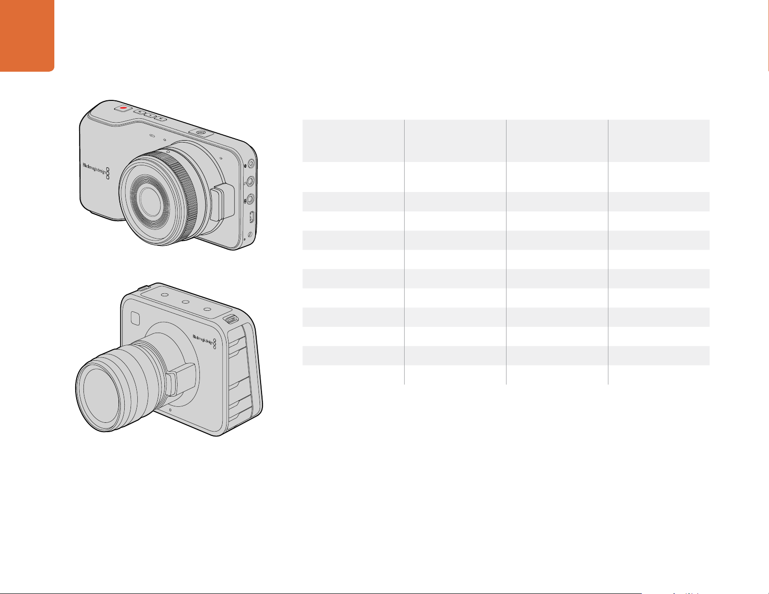
Attaching and removing an MFT lens on Blackmagic Pocket
Cinema Camera and Blackmagic Micro Cinema Camera.
To attach a PL mount lens:
Step 1. Open your camera's PL locking ring by rotating it counterclockwise until it stops.
Step 2. Align one of the lens' four flange notches with the locating pin on the camera mount.
Be sure to align the lens for easy viewing of the lens marks.
Step 3. Tighten the camera's PL locking ring by rotating it clockwise.
Step 4. To remove the lens, rotate the locking ring counterclockwise until it stops, then gently
remove the lens.
When no lens is attached to the camera, the glass filter covering the sensor is exposed to dust and
other debris so you'll want to keep the dust cap on whenever possible.
Attaching and removing an EF lens on Blackmagic Cinema
Camera and Blackmagic Produc tion Camera 4K.
Turning Your Camera On
To turn your camera on, you'll first need to supply power to your camera. Blackmagic Pocket Cinema
Camera and Micro Cinema Camera have removable, rechargeable batteries, while Blackmagic Cinema
SSD
SSD
Camera and Production Camera 4K have rechargeable batteries built in. All Blackmagic Cameras
can be powered simply by plugging the supplied power adapter into their power input. This also
recharges the battery, either built in or plugged in.
The Micro Cinema Camera powers up automatically when power is supplied via an AC adapter using
the expansion port. This means that if you have the camera installed in a remote location or mounted
Attaching and removing a PL lens on Blackmagic Cinema
Camera PL and Blackmagic Produc tion Camera 4K PL.
in an awkward or inconvenient position to access, you don't have to manually turn the camera on
because as long as it is connected to an external power supply, it will always stay powered on.
Page 6
6
Getting Started
6
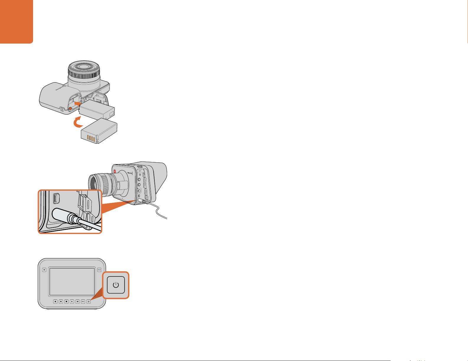
Inser ting the battery into Blackmagic Pocket Cinema Camera.
Inserting a Battery and Powering Blackmagic Pocket Cinema Camera
Your Pocket Cinema Camera uses an EN-EL20 battery. One is included with the camera, but if you
need additional batteries, they can be purchased from your Blackmagic Design reseller or from most
video or photography equipment stores.
Step 1. On the under side of the camera, push the door release towards the lens to access the
battery terminal.
Step 2. With the gold contacts facing into the terminal and the white arrow facing the lens, hook
the lip of the battery under the orange tab and insert the battery until you feel it press
into place. Push the orange tab to release the battery.
Step 3. Close the door to the battery terminal and slide the door release to the right to lock it.
Step 4. Press the power button on the bottom right of the back panel. The status strip will appear
along the top of the LCD.
Step 5. Press and hold the power button to switch off the camera.
Inserting a Battery and Powering Blackmagic Micro Cinema Camera
Your Micro Cinema Camera uses an LP-E6 or LP-E6N battery. One is included with the camera but if
you need additional batteries, they can be purchased from your Blackmagic Design reseller or from
any video or photography equipment store.
Use the supplied power adapter to charge the internal
battery and power the camera.
Press the power button to turn the camera on.
Press and hold to turn the camera off.
Step 1. With the battery's contacts facing the bottom of the camera, gently press the battery
against the battery slot, then slide it down until you feel it click and lock into place. Press
the battery release button on the top panel to remove the battery.
Step 2. To switch on your camera, press the ‘power’ button located on the right panel of the
camera. To switch off, press and hold the 'power' button.
You are now ready to insert an SD card and start recording!
Using Built in Batteries
Blackmagic Cinema Camera and Blackmagic Production Camera 4K have internal batteries that
can be charged using the supplied power adapter. The camera can be charged and operated while
connected via external power and will switch between power sources without any interruption.
You can also charge the camera via a powered USB connection, however it takes longer to charge
so we recommend using the power adapter when possible.
Step 1. Press the power button below the touchscreen. The status strip will appear along the top
of the LCD.
Page 7
7 Installing Media
Installing Media
Step 2. Press and hold the power button to switch off the camera.
You are now ready to insert an SSD and start recording!
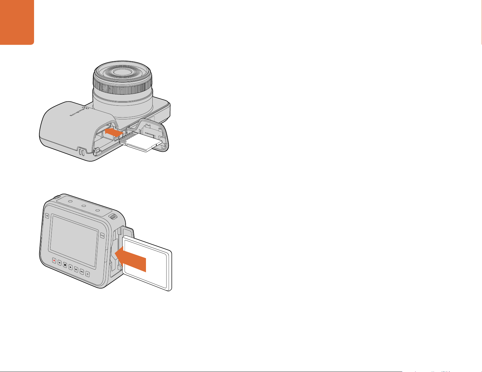
Using an SD Card
If your camera uses an SD card for recording clips, you can insert an SDXC or SDHC card. To insert
an SD card into your camera:
Blackmagic Pocket Cinema Camera
On the underside of the camera, push the battery door release towards the lens. The SD card slot is
located next to the battery terminal. With the metal contacts on the SD card facing towards the lens,
insert the SD card until you feel it lock into place. Push on the SD card to release it.
Inser ting an SD card into the Blackmagic Pocket
Cinema Camera.
Inser ting an SSD into the Blackmagic Cinema Camera
and the Blackmagic Production Camera 4K.
After inserting the SD card and powering your camera, the status strip will display a moving dot while
the camera checks the SD card and then it will say 'ready'.
Blackmagic Micro Cinema Camera
With the SD card's metal contacts facing away from the lens, point the SD card towards the SD card
slot and gently insert the card until you feel it lock into place. Push on the SD card to release it.
The front tally light on the Micro Cinema Camera will flash green three times while the camera checks
the SD card and will stay green when the card is ready.
The supplied SD card is for software installation only and not suitable for video recording. You'll find
a list of recommended SD cards in the 'about SSD and SD cards' section.
Using an SSD
If your camera uses an SSD to record clips, you can insert a 2.5" 9.5 mm SSD formatted in either
the HFS+ or exFAT file systems. To insert an SSD into Blackmagic Cinema Camera and Blackmagic
Production Camera 4K:
Step 1. Open the SSD door on the right hand side of the camera.
Step 2. With the gold SATA contacts facing towards the camera door, insert the SSD until you feel
it press into place. Close the SSD door.
Step 3. Power on the camera. The status strip will display a moving dot while the camera checks
the SSD and then it will say 'ready'
You'll find a list of recommended SSDs in the 'about SSDs and SD cards' section.
Page 8
8
Recording
8
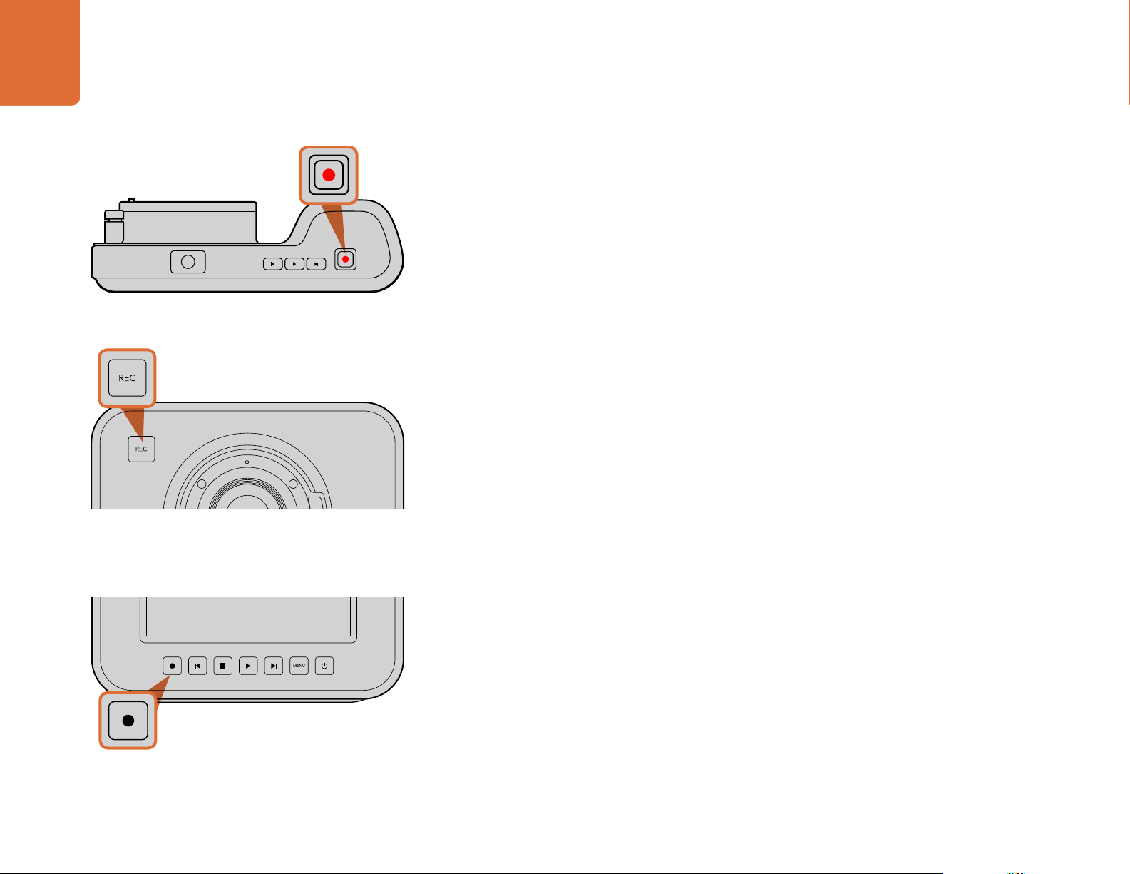
To record a clip, press the 'rec' button on the top of
Blackmagic Pocket Cinema Camera.
Recording
Recording Clips
Press the 'rec' button on your camera to begin recording immediately. Press 'rec' again to stop
recording.
Choosing the Recording Format
Blackmagic cameras record to several different formats, depending on which model you are using.
All Blackmagic cameras record lossless compressed CinemaDNG RAW, plus Apple ProRes codecs
including ProRes 422 HQ, ProRes 422, ProRes 422 LT and ProRes 422 Proxy. ProRes codecs let you
fit more video on your SSD or SD card. ProRes 422 HQ provides the highest quality video with the
lowest compression. Alternatively, ProRes 422 Proxy gives you far more recording time with greater
compression.
Blackmagic Micro Cinema Camera also records RAW 3:1.
Blackmagic Cinema Camera can also record using the Avid DNxHD codec for more options when
you need high quality HD compressed video. You may decide to experiment to see which format
best suits your workflow.
To record a clip on Blackmagic Cinema Camera or Production
Camera 4K, press the 'rec' button on the front face.
or
on the transport control panel.
To select your desired video format:
Step 1. Press the 'menu' button to open the dashboard and select Settings.
Step 2. Select the 'recording' menu and use the selection arrows to set the desired recording format.
Step 3. Press the 'menu' button twice to exit.
Your camera is now ready to record in the video format you have selected. On Blackmagic cameras
with a built in LCD, the current recording format is shown on the LCD status strip.
Page 9
9
Recording
9
Blackmagic Cameras Supported Video Formats
Blackmagic Pocket Cinema Camera
Blackmagic Pocket
Cinema Camera
1080p23.98 1080p23.98 2400 x 1350
1080p24 1080p24 1080p23.98 216 0 p23.98
HDMI
12V
1080p25 1080p25 1080p24 2160p24
1080p29.97 1080p29.97 1080p25 2160p25
1080p30 1080p30 1080p29.97 2160 p 2 9.97
Blackmagic Micro
Cinema Camera
1080p50 1080p30 2160p30
1080p59.94 1080i50 (output) 1080p23.98
1080p60 1080i59.94 (output) 1080p24
Blackmagic
Cinema Camera
12-bit 2.5K RAW
Blackmagic
Production
Camera 4K
4000 x 2160
12-bit 4K RAW
1080p25
1080p29.97
1080p30
Blackmagic Cinema Camera
Page 10
Playback
10
10
Playback
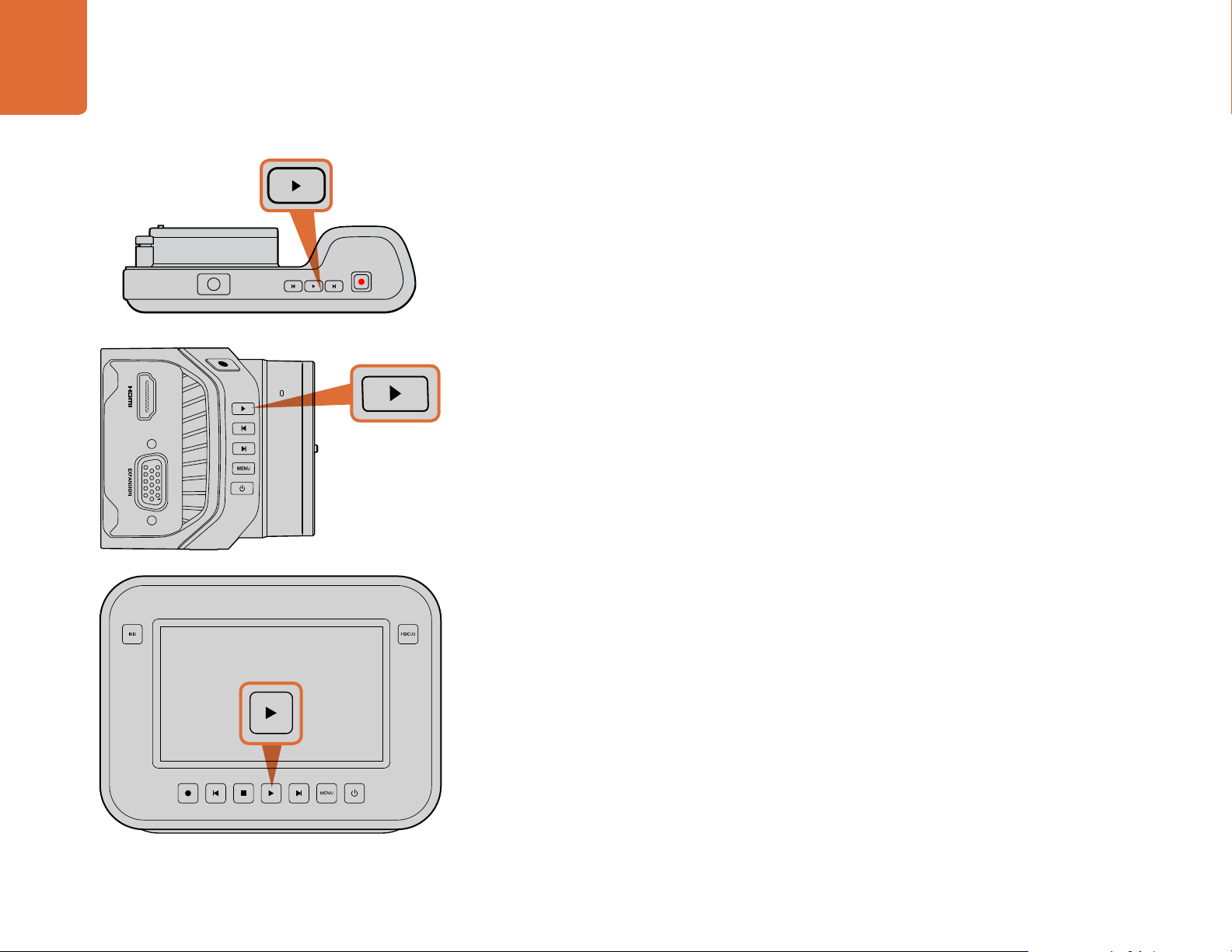
Playing Back Clips
Once you have recorded your video, you can use the transport control buttons to play back your
video on the LCD.
Press the play button once for instant playback and you'll see your video on the LCD and on any
display connected to the HDMI or SDI output. Hold down the forward or reverse buttons to fast
forward or reverse through the clip. Playback will finish when the end of the current clip is reached.
The controls of your camera work just like a CD player, so pressing the forward button will skip to
the start of the next clip. Press the reverse button once to go to the start of the current clip or press
twice to skip back to the start of the previous clip.
On Blackmagic Cinema Camera and Production Camera 4K you can also connect to a Mac or Windows
PC via the Thunderbolt port and monitor your clips using Blackmagic UltraScope. You can check
exposure with the waveform scope, clipping on color channels using RGB parade, color balance using
the vectorscope, audio levels, phase, and more.
To immediately view your recorded clip on a Blackmagic
Camera simply press the 'play' button on the transport controls.
Page 11
11 About SSDs and SD Cards
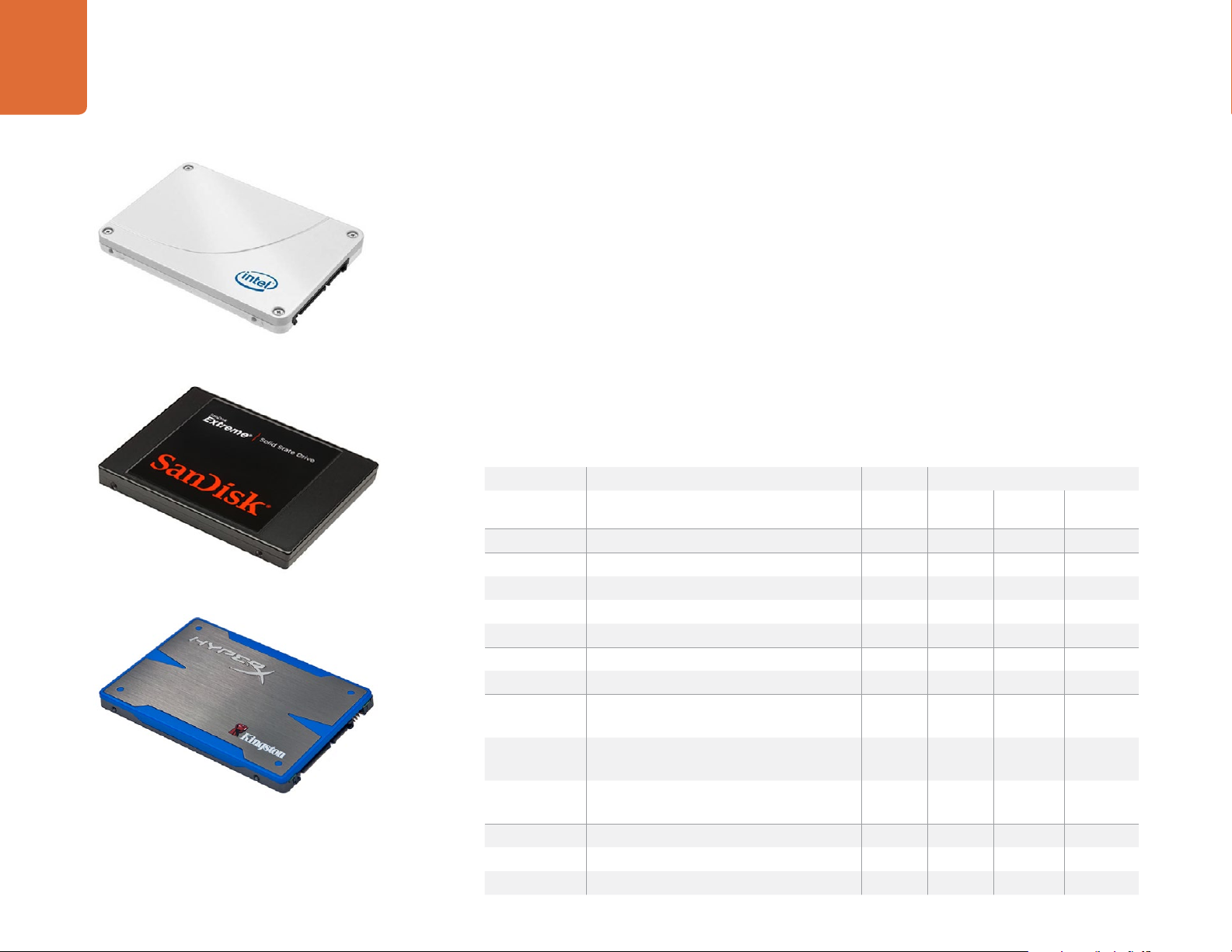
Intel 335 Series 240GB SSD
About SSDs and SD Cards
Choosing a Fast SSD
When working with high data rate video it's important to carefully check the SSD you would like to
use. This is because some SSDs can have a lower sustained write speed than the manufacturer’s
claimed speed, so even though a disk specification can claim an SSD is fast enough to handle video,
in reality the disk may not be fast enough for real time video recording.
Use Blackmagic Disk Speed Test to accurately measure whether your SSD will be able to handle
uncompressed video capture and playback. Blackmagic Disk Speed Test uses data to simulate
the storage of video so you get results similar to what you’ll see when capturing video to a disk.
During Blackmagic testing, we have found newer, larger models of SSD and larger capacity SSDs
are generally faster.
We have provided a table showing SSDs that have tested reliable for video recording and playback.
From a quick glance you can see which SSD is fast enough to handle a chosen format.
Please check the tech notes at the Blackmagic Design support center for the latest information.
SanDisk Extreme 480GB SSD
Kingston HyperX 240GB SSD
Brand SSD Name/Model Number Storage Supported Formats
4K RAW 2.5K RAW
ADATA XPG SX900. ASX900S3-256GM-C 256GB No Yes Yes
Angelbird AV Pro 500GB Ye s Yes Yes
AV Pro 250GB Ye s Yes Yes
AV Pro 480GB No Ye s Ye s
AV Pro 240GB No Yes Yes
Crucial M4 (firmware 009 only). CT512M4SSD2. 512GB No No Ye s
M4 (firmware 000F only). CT256M4SSD2. 256GB No No Ye s
Digistor
Intel 520 series. SSDSC2CW480A310. 480GB No Ye s Ye s
4K Professional Video Series.
DIG-PVD1000, pre-formatted exFat.
Professional Video Series.
DIG-PVD480S, pre-formatted exFat.
Professional Video Series.
DIG-PVD240S, pre-formatted exFat.
520 series. SSDSC2CW240A310. 240GB No Yes Yes
530 series. SSDSC2BW240A401. 240GB No Yes Yes
1TB Yes Yes Yes
480GB No Ye s Ye s
240GB No Yes Yes
ProRes and
DNxHD
Page 12

12 About SSDs and SD Cards
Brand SSD Name/Model Number Storage Supported Formats
4K RAW 2.5K RAW
530 series. SSDSC2BW180A401. 180 GB No Yes Yes
335 series. SSDSC2CT240A4K5. 240GB No Yes Yes
Kingston HyperX Savage. SHSS37A/960G. 960GB Yes Yes Yes
HyperX Savage. SHSS37A/480G. 480GB Ye s Yes Yes
HyperX Savage. SHSS37A/240G. 240GB Yes Yes Yes
HyperX Savage. SHSS37A/120G. 120 GB Yes Yes Ye s
HyperX 3K. SH103S3/480G. 480GB No Ye s Ye s
HyperX 3K. SH103S3/240G. 240GB No Yes Yes
SSDNow KC300. SKC300S37A/480G. 480GB No Ye s Ye s
SSDNow KC300.SKC300S37A/240G. 240GB No Yes Yes
OCZ Agility 3. AGT3-25SAT3-240G. 240GB No No Ye s
OWC
Samsung 850 Pro. MZ-7KE2T0BW, spacer required 2TB Yes Yes Yes
SanDisk Extreme Pro. SDSSDXPS-240G-G25. 240GB Yes Yes Yes
PNY Prevail. SSD9SC480GCDA-PB. 480GB No Ye s Ye s
Mercury Extreme Pro 6G.
OWCSSD7P6G480.
Mercury Extreme Pro 6G.
OWCSSD7P6G240.
Mercury Extreme Pro 6G.
OWCSSD7P6G120.
850 Pro. MZ-7KE1T0BW, spacer required. 1TB Yes Yes Yes
850 Pro. MZ-7KE512BW, spacer required. 512GB Yes Yes Yes
850 Pro. MZ-7KE256BW, spacer required. 256GB Yes Yes Ye s
Extreme Pro. SDSSDXPS-480G-G25. 480GB Ye s Yes Yes
Extreme Pro. SDSSDXPS-960G-G25. 960GB Ye s Yes Yes
Extreme. SDSSDX-480G-G25. 480GB No Ye s Yes
Extreme. SDSSDX-240G-G25. 240GB No Yes Yes
Extreme. SDSSDX-120G-G25. 120 GB No No Yes
Prevail. SSD9SC240GCDA-PB. 240GB No Yes Yes
480GB No Ye s Ye s
240GB No Yes Yes
120GB No Yes Yes
ProRes and
DNxHD
Page 13

13 About SSDs and SD Cards
Brand SSD Name/Model Number Storage Supported Formats
4K RAW 2.5K RAW
PNY XLR8. SSD9SC480GMDA-RB. 480GB No Ye s Yes
CL4100. SSD7S480GCL4. 480GB No No Yes
CL4100. SSD7S240GCL4. 240GB No No Yes
Transcend SSD370. TS1TSSD370. 1TB No Yes Yes
SSD370. TS512GSSD370. 512GB No Ye s Ye s
Transcend SSD370. TS256GSSD370. 256GB No Yes Yes
SSD720. TS256GSSD720. 256GB No Yes Yes
Wise Cinema CMS-0240 240GB Yes Yes Ye s
Important Notes About SSD Speed
If your SSD is dropping frames, try a different SSD or use a compressed HD recording format such as
ProRes or DNxHD for lower data rates. Check the Blackmagic Design website for the latest information.
ProRes and
DNxHD
Choosing a Fast SD Card
It's important to use SDHC and SDXC cards with Blackmagic Pocket Cinema Camera and Blackmagic
Micro Cinema Camera. These cards are rated for fast data speeds and support larger storage sizes.
We have provided a table showing SD cards that have tested reliable for video recording and playback.
From a quick glance you can see which SD card is fast enough to handle a chosen format.
Please check the tech notes at the Blackmagic Design support center for the latest information.
Brand SD Card Name/Type Storage Supported Formats
RAW ProRes
Delkin Devices Elite SDHC UHS-I. 32GB No Yes
Elite SDHC UHS-I. 16GB No Yes
SanDisk Extreme Pro. 95 MB/sec SDXC UHS-I 512GB Yes Yes
Extreme Pro. 95 MB/sec SDXC UHS-I 256GB Yes Ye s
Extreme Pro. 95 MB/sec SDXC UHS-I 128GB Yes Yes
Extreme Pro. 95 MB/sec SDXC UHS-I 64GB Ye s Ye s
Page 14
14 About SSDs and SD Cards
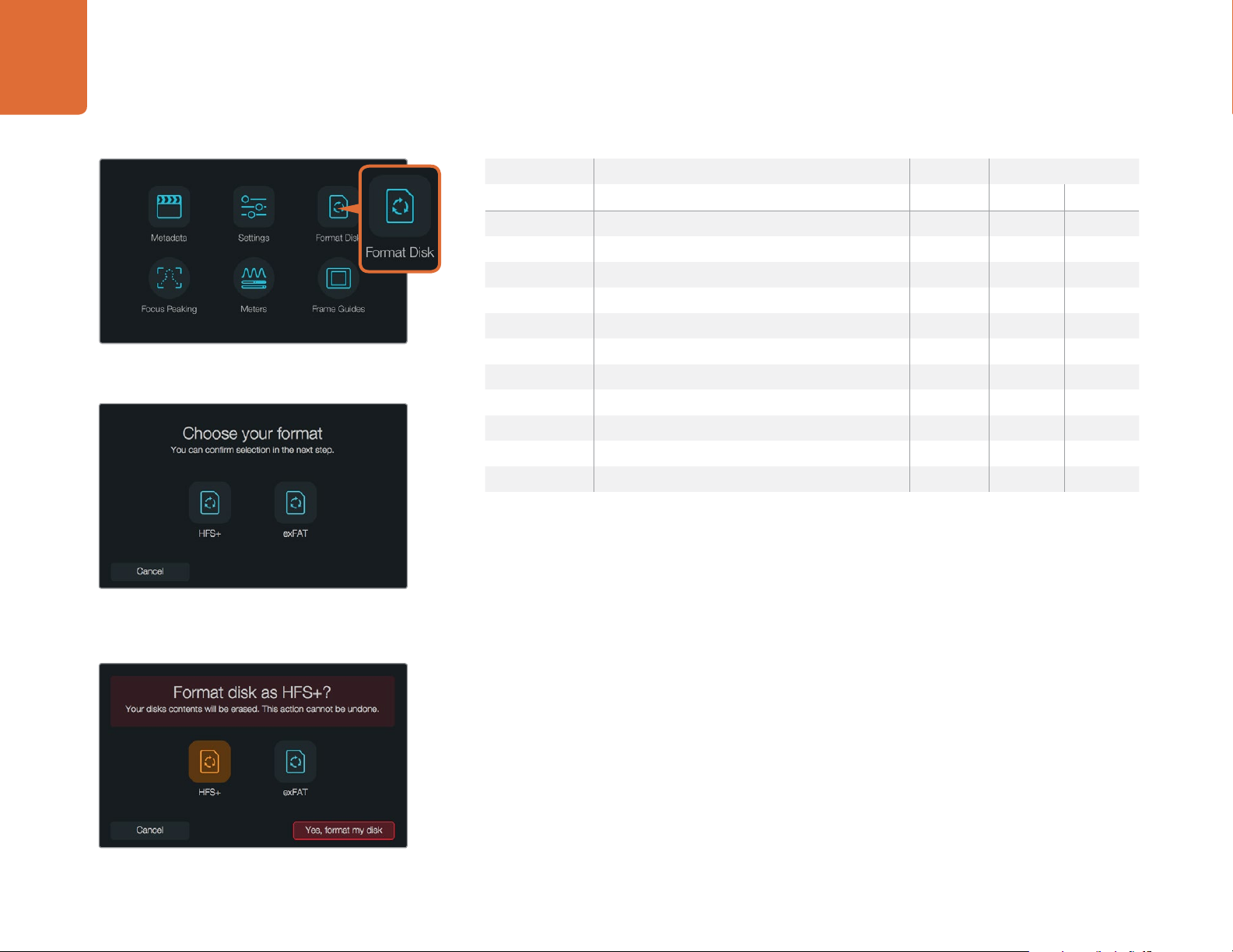
Select the 'format disk' or 'format card' icon on the camera
dashboard to format your SSD or SD card.
Brand SD Card Name/Type Storage Supported Formats
RAW ProRes
Extreme Pro. 95 MB/sec SDHC UHS-I 32GB Ye s Ye s
Extreme Plus. 80 MB/sec SDXC UHS-I 128GB Yes Yes
Extreme Plus. 80 MB/sec SDXC UHS-I 64GB No Yes
Extreme Plus. 80 MB/sec SDHC UHS-I 32GB No Yes
Extreme Plus. 80 MB/sec SDHC UHS-I 16GB No Yes
Extreme Plus. 80 MB/sec SDHC UHS-I 8GB No Yes
Extreme. 45 MB/sec SDXC UHS-I 128GB No Yes
Extreme. 45 MB/sec SDXC UHS-I 64GB No Yes
Extreme. 45 MB/sec SDHC UHS-I 32GB No Yes
Extreme. 45 MB/sec SDHC UHS-I 16GB No Yes
Extreme. 45 MB/sec SDHC UHS-I 8GB No Ye s
Preparing Media for Recording
Choose from HFS+ or exFAT formats. Confirm your selection
by tapping the 'yes, format my disk /card' icon to continue,
or 'cancel' to cancel the format.
SD cards used by Blackmagic Pocket Cinema Camera and Micro Cinema Camera, and SSDs used by
Blackmagic Cinema Camera and Production Camera 4K must be formatted as either HFS+ or exFAT.
These disk formats allow long clips to be recorded as single files and can be formatted using the
'format disk' feature on the dashboard, or using the 'settings menu' on Blackmagic Micro Cinema
Camera. To see the 'settings menu' on Blackmagic Micro Cinema Camera, plug in an HDMI monitor
into the HDMI port or plug in a composite video display unit using the composite video out connector
from the expansion cable.
You can also format SD cards and SSDs via a Mac or PC computer. SSDs can be formatted using an
SSD dock such as Blackmagic MultiDock.
HFS+ is also known as Mac OS Extended. It is the recommended format as it supports "journaling".
Data on journaled media is more recoverable and less likely to be corrupted. HFS+ is natively
supported by Mac OS X.
ExFAT is supported natively by Mac OS X and Windows without needing to purchase any additional
software. However, exFAT does not support journaling which means data is less protected against
the rare event your media card or SSD is corrupted.
Page 15
15 About SSDs and SD Cards
Use 'disk utility' on Mac OS X to erase your SSD or SD card
in the Mac OS extended (journaled) or exFAT format.
To format your SSD or SD card using the camera settings:
Step 1. Press the 'menu' button to open the dashboard, or to open the settings menu on Blackmagic
Micro Cinema Camera.
Step 2. Select the 'format disk' or 'format card' icon by tapping on the touchscreen or using the
navigation and 'ok' buttons on the Blackmagic Pocket Cinema Camera. On Blackmagic
Micro Cinema Camera, press the 'right' arrow button to navigate through the settings and
press the 'play' button to select 'setup'>'card'.
Step 3. Choose your format by selecting the HFS+ or exFAT icon.
Step 4. A warning will appear asking you to confirm the format. Select 'yes, format my disk/card'
to continue, or 'cancel' to cancel the format.
Step 5. A progress bar shows you the progress of the format. 'Complete' will appear when the
format is done. It is important not to remove cards or SSDs while they are formatting.
Step 6. Select the 'done' icon to return to the dashboard, or press the 'menu' button on
Blackmagic Micro Cinema Camera to return to the main menu settings.
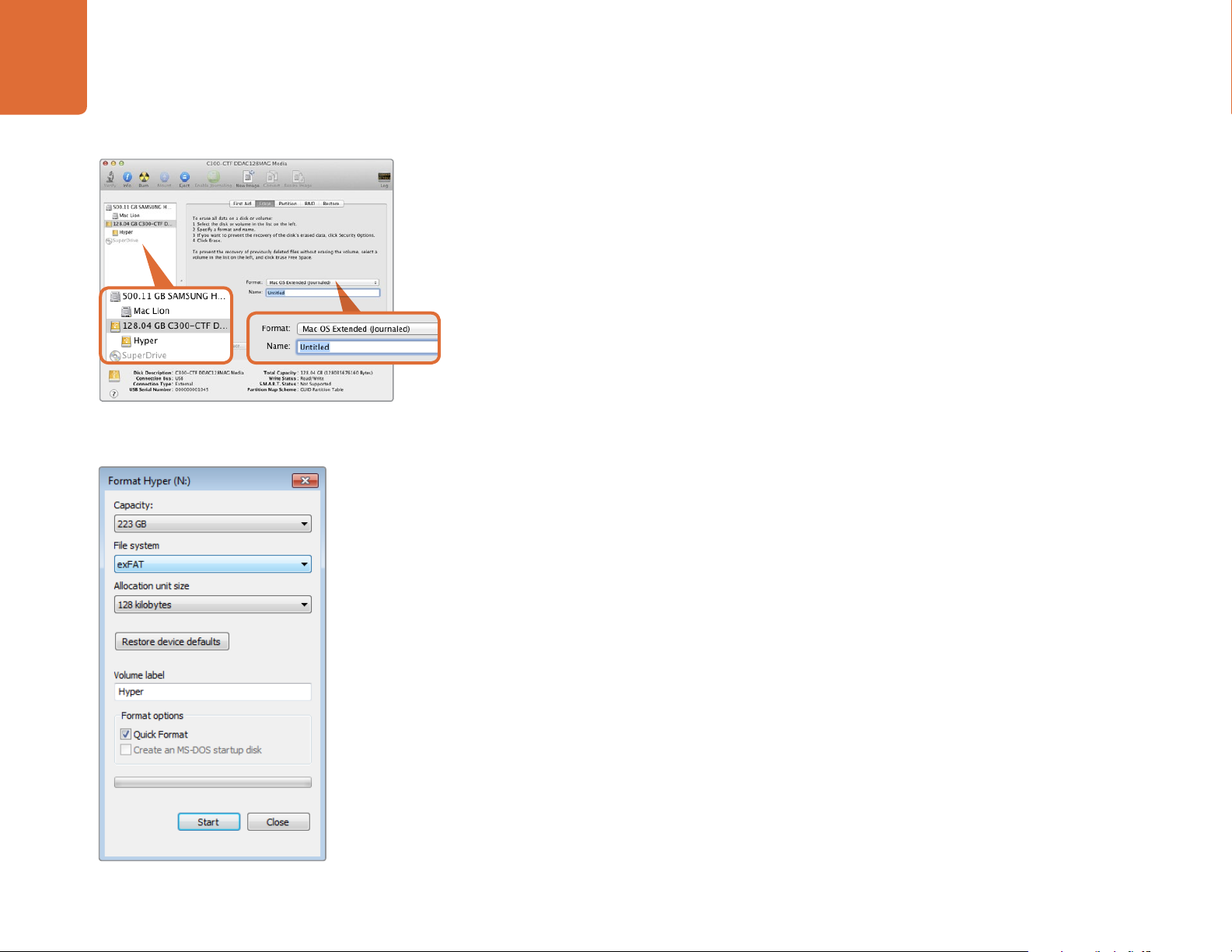
Preparing SSDs and SD Cards on a Mac OS X computer
Use the 'disk utility' application included with Mac OS X to format or initialize your SSD or SD card
in the HFS+ or exFAT formats. If your SSD or SD card already has files recorded on them, remember
to back up your media as all data will be lost when it is formatted.
Use the 'format' dialog box feature in Windows
to format your SSD or SD card in the exFAT format.
Step 1. Connect the SSD to your computer with an external dock, such as Blackmagic MultiDock,
or cable adapter and dismiss any message offering to use your SSD for time machine
backups. Plug an SD card into your computer's SD card slot or via an SD card reader.
Step 2. Go to 'applications/utilities' and launch 'disk utility'.
Step 3. Click on the disk icon of your SSD or SD card and then click the 'erase' tab.
Step 4. Set the format to 'Mac OS extended (journaled)' or "exFAT".
Step 5. Type a 'name' for the new volume and then click 'erase'. Your SSD or SD card will quickly
be formatted and made ready for use.
Page 16
16 About SSDs and SD Cards
Use Disk Speed Test to find out the performance of your
media drives.
Preparing SSDs on a Windows computer
The 'format' dialog box can format an SSD or SD card in the exFAT format on a Windows PC. Remember
to back up anything important from your media as all data will be lost when it is formatted.
Step 1. Connect the SSD to your computer with an external dock, such as Blackmagic MultiDock, or
cable adapter. Plug an SD card into your computer's SD card slot or via an SD card reader.
Step 2. Open the 'start menu' or 'start screen' and choose 'computer'. Right-click on your SSD
or SD card.
Step 3. From the contextual menu, choose 'format'.
Step 4. Set the file system to 'exFAT' and the allocation unit size to 128 kilobytes.
Step 5. Type a volume label, select 'quick format' and click 'start'.
Step 6. Your SSD or SD card will quickly be formatted and made ready for use.
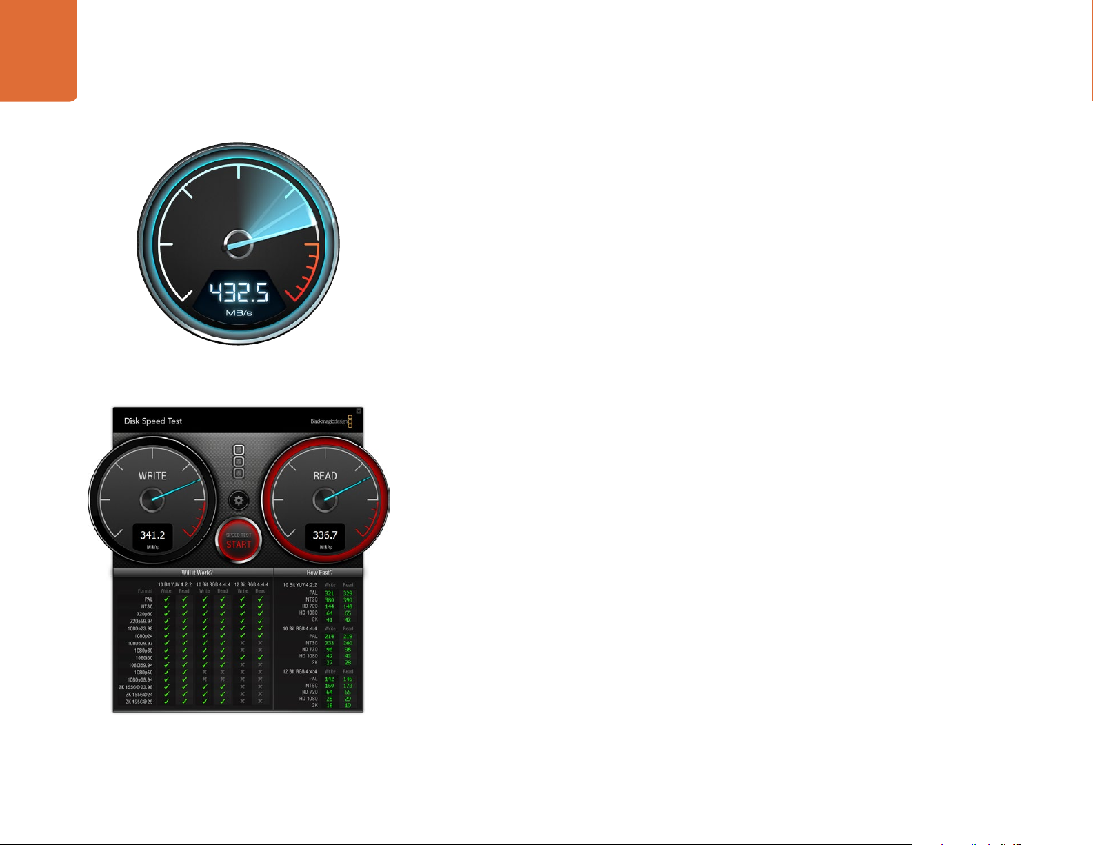
Checking Disk Speed
Blackmagic Disk Speed Test is a fun application that measures the read and write performance of
storage media, then displays the results using video formats.
If you have ever wondered whether your hard drive is suitable for recording ("write") or playback
(“read”) of a particular video format, you can use Disk Speed Test to find out. Test the performance
of your media drives with a single click of the 'start' button! Disk Speed Test will even show you how
many streams of video your storage is capable of handling.
Disk Speed Test interface.
Disk Speed Test is installed by the Desktop Video Software. It is also available as a free download
for Mac OS X from the Mac App Store.
Page 17
17 Camera Connections
HDMI
12V
Camera Connections
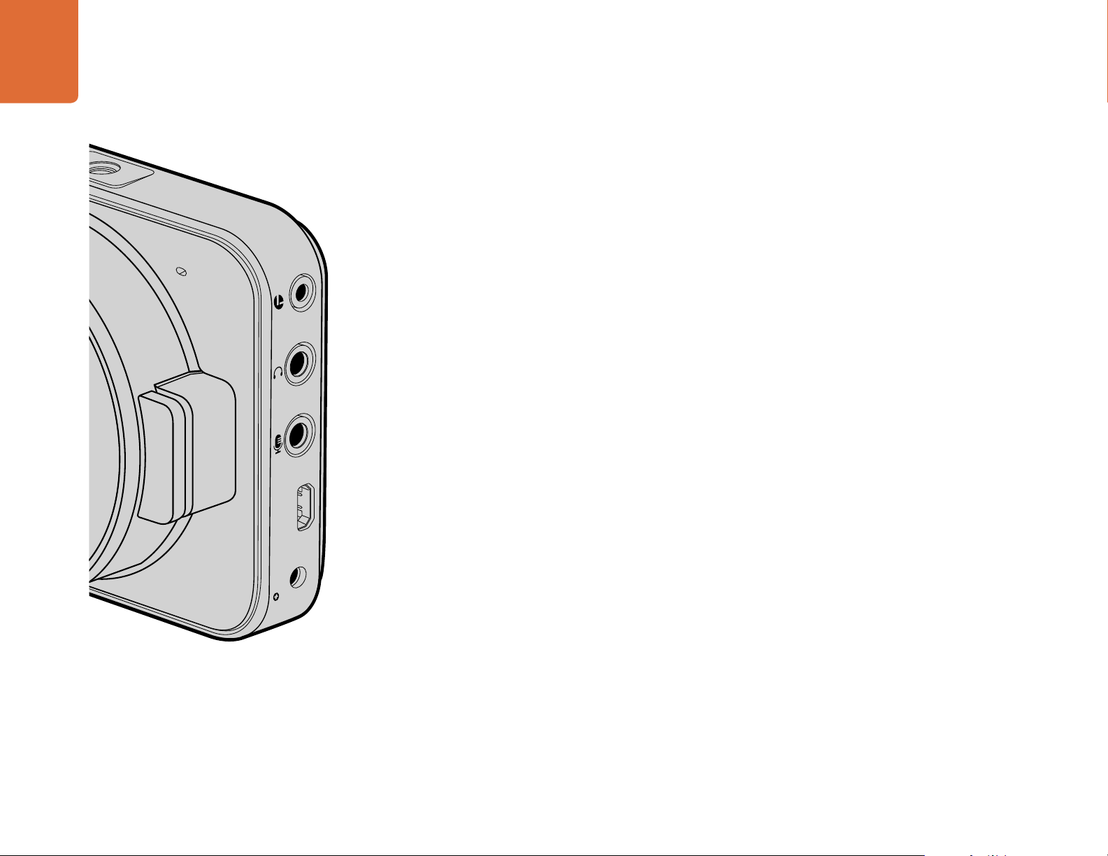
Blackmagic Pocket Cinema Camera
LANC Remote Control
The remote port on your camera is used to remotely control record starting and stopping, iris
adjustments and manual focus adjustments when using a compatible lens.
The port is a 2.5 mm stereo jack using the standard LANC protocol.
Headphones
Monitor audio while recording or playing back clips by plugging your headphones into the 3.5mm
stereo headphones jack.
Audio In
The 3.5mm stereo audio connector accepts microphone or line level audio. It's important to select
the appropriate setting or your audio may sound too quiet or too loud. The camera automatically
switches to line level if the audio is too loud for a sustained period.
HDMI Out
The micro HDMI port outputs 10-bit uncompressed HD1080p video, even while recording. It can be used
to output video to routers, monitors, capture devices, broadcast switchers and other HDMI devices.
Power
Use the 0.7mm 12 – 20V power input for connecting your power supply and to charge the battery.
USB
Use the USB port to connect your Blackmagic Pocket Cinema Camera to your computer and update
the internal software. The USB port can be found inside the battery compartment.
Page 18
18 Camera Connections
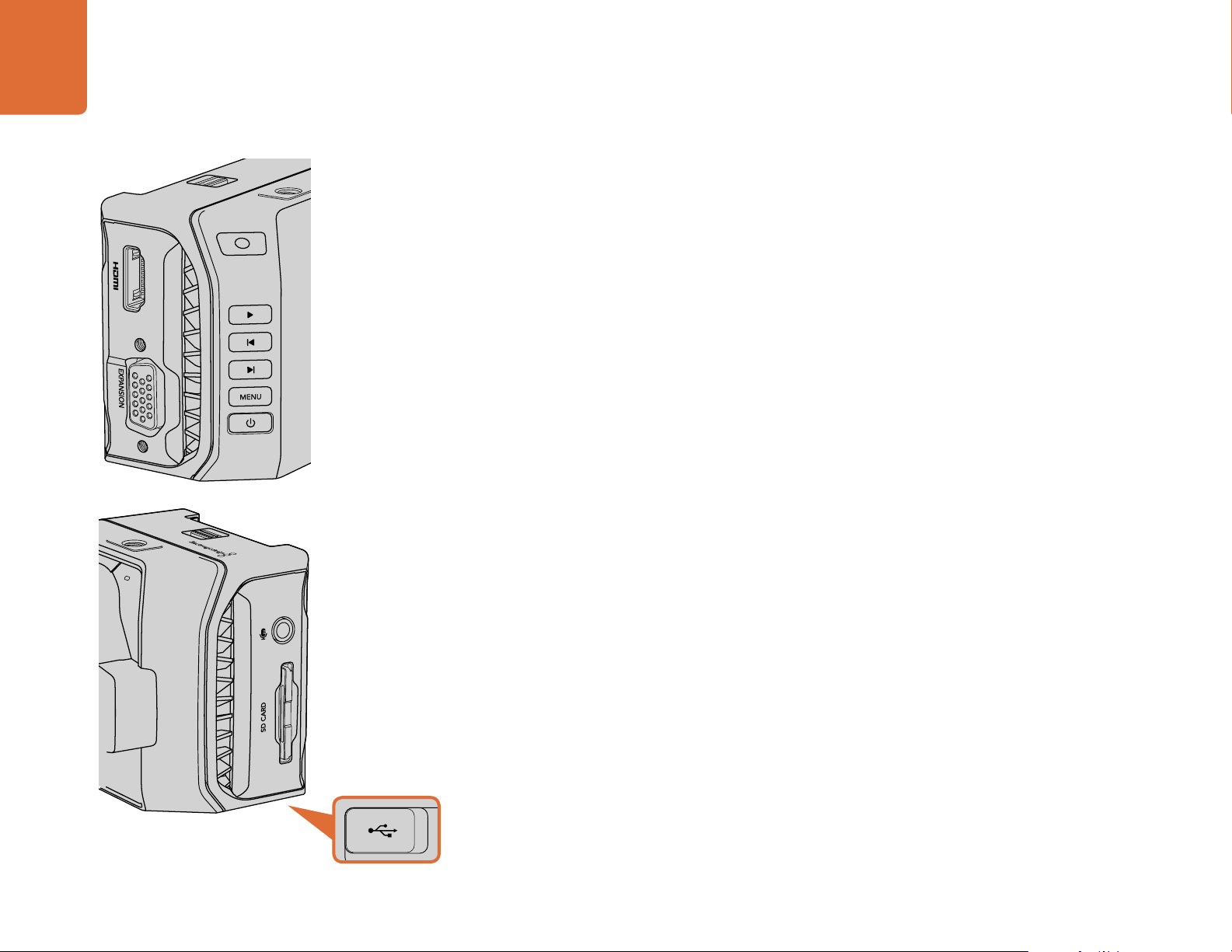
Blackmagic Micro Cinema Camera
HDMI Out
The HDMI output supports 10-bit 4:2:2 1080p HD video with 2 channels of embedded audio. This
gives you the option to either send a clean video feed or insert overlays on the HDMI output from
the camera menu.
Expansion Port
The expansion port is a standard DB-HD15 connector which includes connections such as +12v power,
analog servo, BNC and RCA connectors. The DB-HD15 is actually quite an old fashioned connector
and it was chosen because its extremely easy to solder wires to it and the plugs are very common
so are easy to purchase. This means you don't have to use the included breakout cable as you can
make up your own custom cables simply by soldering the wires you need to the relevant pins on the
DB-HD15 plug. If you look closely at the pins you can see the pin numbers.
This makes it easy to look up the connector signal layout and connect the wires you need. You can
add a backshell to the DB-HD15 on custom cables or you can even put a little silicon compound on
the plug to keep it small when the camera is being used on a moving mount.
For more information about the expansion port and expansion cable, refer to the ‘Micro Cinema
Camera Expansion Port’ section on the following page.
The USB por t is located on the bottom of the Micro
Cinema Camera.
Analog Audio In
The 3.5mm stereo audio connector accepts both microphone and line level audio, selectable in the
camera menu. The microphone level audio is lower than the line level audio so if you are connecting
a microphone to the camera and have the line level selected, you will find that the levels will be
too low. You can also use the analog audio input for embedding timecode onto your video clip by
sending an SMPTE compliant LTC timecode in the left audio channel and selecting the timecode
option in the camera menu.
USB
Use the mini USB port to connect your Blackmagic Micro Cinema Camera to your computer for
software updates. The USB port can be found on the bottom of the camera.
Page 19
19 Camera Connections
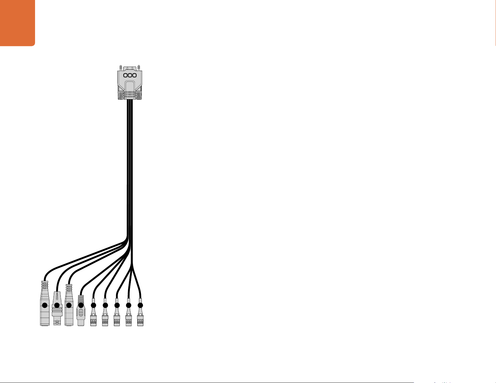
Blackmagic Micro Cinema Camera Expansion Port and Expansion Cable
There are two ways to access the expansion port’s functions. You can use the expansion cable that
comes with your Micro Cinema Camera, or solder your own custom connectors.
Blackmagic Micro Cinema Camera has a standard DB-HD15 serial connector and can be used with
the included expansion cable for the following control options:
1. Power Input
The 12V power input connects via a DC jack and provides power to the Micro Cinema Camera,
as well as trickle charging any batteries attached. When mains power is supplied, the camera will
automatically turn on.
2. Reference Input
This allows multiple cameras to be genlocked to a blackburst or tri-level reference signal. Genlocking
cameras to an external reference signal helps to prevent timing errors which may result in the picture
jumping when switching between different cameras.
3. LANC
Connect wired LANC remote controllers to the 2.5mm jack for controlling functions like recording
start and stop, iris adjustment, and manual focus from a tripod arm when using compatible lenses.
1
2 3 4 5 6 7 8 9
Blackmagic Micro Cinema Camera Expansion Cable
4. Composite Video Out
Standard definition composite video output via an RCA connector. You can connect this output to
any low cost composite display device or even a wireless composite transmitter. The output can be
selected to be either NTSC or PAL standard from the camera's menu.
5 - 8. Analog Servo Ch1 - Ch4
The four analog servo ports are connected with the Futaba J connectors to a compatible receiver
unit. This is used to wirelessly control your camera. Each PWM analog input operates a single channel
that can drive a feature such as lens focus, iris and servo zooms. You can also connect a simple switch
so that you can quickly toggle the camera to start and stop recording. The camera will treat each
of the analog channel as a switch until it detects a PWM signal. Once a PWM signal is detected, it
will automatically latch on and respond to PWM signals. Power cycle the camera if you want to use
a switch to control the camera.
9. S.Bus Digital Servo
By connecting to a compatible S.Bus receiver using the Futaba J cable, you have 18 S.Bus remote
channels where features of the camera can be assigned to and remotely controlled. These features can
include focus, servo zoom, iris control and other such features. For more information about mapping
functions to S.Bus remote channels, see the ‘Remote Settings’ section of this manual.
Page 20

20 Camera Connections
Wiring Diagram for the Blackmagic Micro Cinema Camera Expansion Cable
When using Blackmagic Micro Cinema Camera’s expansion port, you may only
want to access one or two functions. For example, you may want to use the
composite video output feature while simultaneously controlling the zoom
function. It’s easy to make a connector that will give you just these functions
without the clutter of additional, unused connectors.
P1
GROUND
GROUND
GROUND
5
15
10
4
14
9
3
13
8
2
12
7
1
11
6
GROUND
GROUND
GROUND
Use the following diagram when wiring the expansion cable included or use
it as an example of how you can wire up the connections on you own custom
cable correctly. The full range of available pins are listed under group P1, while
subsets used for particular functions, as well as their layout within the appropriate
connectors, are shown in groups P2 through P7.
PIN ASSIGNMENT
2
3
8
12
13
15
S. Bus
Analog Servo Ch1
Analog Servo Ch2
Analog Servo Ch3
Analog Servo Ch4
Composite Video Out
TIP
RING
1
2
3
1
2
3
1
2
3
1
2
3
1
2
3
P2
P3
P4
P5
P6
P7
1 Ground
2 S. Bus
3 Analog Servo Ch1
4 Ground
5 Reference Input
6 Power +12V in
7 Ground
8 Analog Servo Ch2
9 LANC Data
10 LANC Power
11 Ground
12 Analog Servo Ch3
13 Analog Servo Ch4
14 +5V 400mA Out
15 Composite Video Out
GROUND
10
GROUND
GROUND
5
9
6
Reference Input
LANC Data
LANC Power
Power +12V in
TIP
RING
TIP
RING
SLEEVE
PIN
SLEEVE
P8
P9
P10
Page 21

21 Camera Connections
Blackmagic Cinema Camera and Production Camera 4K
LANC Remote Control
The remote port on your camera is used to remotely control record starting and stopping, plus iris
and focus adjustments when using a compatible lens on Blackmagic Cinema Camera and Production
Camera 4K EF models.
The port is a 2.5 mm stereo jack using the standard LANC protocol.
Headphones
Monitor audio while recording or playing back clips by plugging your headphones into the 3.5mm
stereo headphones jack.
Audio In
The 1/4 inch TRS Phone audio connectors accept microphone or line level audio. It's important to
select the appropriate setting or your audio may sound too quiet or too loud. The camera automatically
switches to line level if the audio is too loud for a sustained period.
SDI Out
Blackmagic Cinema Camera supports 3G-SDI so it can be used to output uncompressed 10-bit 4:2:2
video to routers, monitors, SDI capture devices, broadcast switchers and any other SDI devices.
Blackmagic Production Camera 4K supports 6G-SDI, so it can be used to connect to any SDI monitor
as well as 4K switchers such as ATEM Production Studio 4K.
Thunderbolt
When connected to a Mac OS X or Windows computer with Thunderbolt technology, your Blackmagic
Cinema Camera or Production Camera 4K can be used as a powerful solution for waveform
monitoring and color correction. Blackmagic Cinema Camera's Thunderbolt port always outputs
10-bit uncompressed HD1080p video. Production Camera 4K's Thunderbolt port matches the SDI
output, which can be 10-bit uncompressed HD1080p or Ultra HD 4K.
Power
Use the 12 – 30V power input for connecting your power supply and to charge the internal battery.
USB
Use the USB port to connect your Blackmagic Cinema Camera or Production Camera 4K to your
computer and update the internal software. Open the SSD door to access the USB port.
Page 22

22 Tally Light Indicators
SD CARD
Tally Light Indicators
Blackmagic Micro Cinema Camera Tally Light
Blackmagic Micro Cinema Camera includes a tally light feature. The tally light indicates the following
camera scenarios to the camera operator:
White - Power On
Red - Recording
Green (flashes 3 times) - SD card is being inserted and recognised
Green - SD card is present in the camera / camera is playing back.
Red (flashing slowly) - Card filling up
Red (flashing quickly) - Dropped Frames
Red, Orange (alternating slowly) - Battery low when recording
White, Orange (alternating slowly) - Battery low when in standby
You can adjust the brightness of the tally light in Micro Cinema Camera's settings. See the 'camera
settings' section for more information.
The tally light is located at the top of Blackmagic Micro
Cinema Camera's lens.
Page 23

23 Menu Settings
Press the 'menu' but ton to open the dashboard.
Menu Settings
Dashboard
The dashboard feature is opened by pressing the 'menu' button. From the dashboard you can access
the 'settings' menu and key features such as metadata, media formatting, activating meters, frame
guides and focus peaking. Press 'menu' again to exit the dashboard.
To view menu settings on Blackmagic Micro Cinema Camera, simply connect an external monitor
such as the Blackmagic Video Assist to the HDMI port or use the composite output on the expansion
cable to connect to a low cost composite display. Pressing the 'menu' button brings you directly to
the menu screen. You can also use the composite output on the expansion cable to connect to a
low cost composite display.
Camera Settings
To configure camera settings on your Blackmagic camera, press the 'menu' button to open the
dashboard, select the 'settings' icon, then select the camera icon to the left of the settings menu.
If you want to bypass the dashboard for direct access to the menu screen, simply hold down the
menu button. Pressing the 'menu' button in Micro Cinema Camera opens the menu settings display.
The 'camera' settings screen lets you adjust key features such
as ISO, white balance, shutter angle, date, time and camera ID.
Change the camera ID using the onscreen keyboard.
Blackmagic Pocket Cinema Camera
Press the up and down buttons to highlight each settings menu. Press 'ok' to enter a settings menu.
Use the left and right directional arrows to adjust values and the up and down arrows to move between
settings. Press 'menu' again to return to selecting between main settings pages.
Blackmagic Micro Cinema Camera
Press the left and right arrow buttons to navigate and change settings. Press the 'play' button to
highlight a setting and to confirm a change. Press the 'menu' button to return to the menu screen.
Blackmagic Cinema Camera & Production Camera 4K
Tap or slide the relevant arrows and icons on the touchscreen to change values or switch between
settings menus.
Camera ID
If using more than one Blackmagic Camera, it's helpful to set each camera's ID which will be included
with any metadata recorded with your clips. Set the camera ID with the onscreen keyboard. When you
have finished entering a new camera ID, select 'enter' to save, or select 'cancel' to discard any changes.
If you're using the Blackmagic Micro Cinema Camera, you will find the 'camera number', 'date' and
'time' settings in the 'setup' menu.
Page 24

24 Menu Settings
The 'camera' settings screen.
Setting Date and Time
To set date and time on your Blackmagic Pocket Cinema Camera, select the + or - buttons to change
the year, month and day settings.
Time is set to 24 hour format on Blackmagic Cameras. To set the time, select the + and - keys to
make adjustments to the time. If traveling with your Blackmagic Camera, remember to change the
date and time to local time zones.
If you have your Blackmagic Camera stored for long periods, the time may need to be reset. It is
always a good idea to check the time and date prior to recording. When connecting your camera
to your computer via USB and launching Blackmagic Camera Setup, your computer's time is synced
to your camera.
ISO
ISO settings are helpful when you are shooting in a variety of light conditions. The optimum ISO
setting for the Blackmagic Micro Cinema Camera, Pocket Cinema Camera and Cinema Camera is
800ASA with a maximum ISO of 1600ASA. For Production Camera 4K the optimum setting is 400ASA
with a maximum ISO of 800ASA.
Depending on your situation, however, you may choose a lower or higher ISO setting. For example,
in low light conditions 1600ASA would be suitable, or 800ASA for Production Camera 4K, but may
introduce some visible noise. In bright conditions 400ASA, or 200ASA on Production Camera 4K,
would be best to record richer colors.
Adjust the ISO settings using the arrow icons in the menu.
White Balance
Blackmagic Cameras include white balance presets for a variety of color temperature conditions.
Each light source emits a warm or cool color. Warm appears red and cool appears blue, so the white
balance setting adds opposing red or blue to compensate. This makes sure white stays white in
your image. Color temperature also changes depending on the position of the sun and the cloud
conditions. For example, light is warm at sunrise, cools down until midday, then warms up again as
the sun sets. Shady areas in your picture, including overcast conditions, will generally appear blue.
Use the following guide to set your white balance to compensate for the changing light conditions:
2500, 2800, 3000, 3200, 3400, 3600, 4000, 4500 and 4800K for various conditions under
tungsten, incandescent or fluorescent light, or under dull natural light including candle
light, sunrise/sunset, morning, and after noon light.
5000, 5200, 5400 and 5600K for outdoors on a clear, sunny day.
6000, 6500, 7000, 7500 and 8000K for a variety of daylight conditions.
Page 25

25 Menu Settings
Adjust the White Balance settings using the arrow icons in the menu.
Shutter Angle
Shutter angle complements the ISO setting by regulating the amount of light on the sensor.
180 degrees is the optimum shutter angle, however as lighting conditions change you may need
to adjust accordingly. For example, 360 degrees is considered 'wide open' and allows maximum
light onto the sensor. This is useful for low light conditions. If you notice lights are flickering,
172.8 degrees will minimize this effect when shooting 24p in countries with 50 hertz power supplies.
Adjust the 'shutter angle' settings using the arrow icons in the menu.
Auto Exposure
Blackmagic Micro Cinema Camera has the following auto exposure options.
Iris
Maintains a constant shutter speed while changing the aperture to achieve a constant exposure.
Shutter
Maintains a constant aperture while changing the shutter speed to achieve a constant exposure.
The 'camera' settings screen in Blackmagic Micro
Cinema Camera.
Iris + Shutter
Maintains a constant exposure level by adjusting the aperture. If the maximum or minimum available
aperture is reached and exposure still cannot be maintained, Micro Cinema Camera will begin
adjusting the shutter speed to keep exposure constant.
Shutter + Iris
Maintains the correct exposure levels by adjusting the shutter speed. If the maximum or minimum
available shutter speed is reached and exposure still cannot be maintained, Micro Cinema Camera
will begin adjusting the aperture to keep exposure constant.
Manual Trigger
Iris aperture and shutter speed are set manually and exposure may vary with changing light conditions.
Page 26

26 Menu Settings
The 'audio' settings screen lets you adjust the microphone
input level, input level type, audio channel levels, mirror ch 1
audio to ch 2, and adjust the headphones or speaker volume.
Audio Settings
To adjust audio input and audio monitoring settings on your Blackmagic Camera, press the 'menu'
button to open the dashboard, select the 'settings' icon, then select the microphone icon to the left
of the settings menu.
On Blackmagic Micro Cinema Camera, press the 'menu' button to enter the menu settings display.
Use the left and right arrow buttons to move and select 'audio', then press the 'play' button to
confirm your selection.
Microphone Input
Microphone input adjusts the recording levels of the built in microphone. Move the audio slider left
or right to increase or decrease levels. Blackmagic Micro Cinema Camera and Blackmagic Pocket
Cinema Camera have built in stereo microphones, and Blackmagic Cinema Camera and Production
Camera 4K have built in mono microphones. The built in microphones record to audio channels 1
and 2 when no external audio source is connected.
Input Levels
External audio connectors accept audio at microphone level or line level. It's important to select
'mic' or 'line' level audio as appropriate to avoid your external audio sounding almost inaudible or
too hot and distorted.
The 'audio' settings in Blackmagic Micro Cinema Camera.
Set the external audio input levels by using the left and right arrows, or if you're using the Blackmagic
Micro Cinema Camera, use the left and right arrow buttons on the camera.
Page 27

27 Menu Settings
Channel 1 Input
To increase or decrease levels for channel 1, move the audio slider icon left or right. If you're using
the Micro Cinema Camera, use the left and right arrow buttons on the camera. The external audio
input overrides the built in microphone and is recorded to audio channel 1.
Channel 2 uses Channel 1 Input
Select 'yes' if you only have channel 1 input and want to record the same external audio to channels
1 and 2. You can leave this set to 'no' if you only want to record one channel of audio.
Channel 2 Input
To increase or decrease levels for channel 2, move the audio slider icon left or right. If you're using
the Micro Cinema Camera, use the left and right arrow buttons on the camera. The external audio
input overrides the built in microphone and is recorded to audio channel 2.
Headphone and Speaker Volume
When headphones are connected, a headphone icon will be displayed. When no headphones are
detected, a speaker icon will be displayed. Headphones will always be active when recording or
playing back, however speakers will only work when playing back. Move the volume slider left or
right to increase or decrease audio monitoring levels.
Audio Input
Select if your audio input is from the 'camera' or from an external audio 'input' such as a microphone.
Automatic Gain Control
Setting the automatic gain control to 'on' will allow your Blackmagic Micro Cinema Camera to
automatically adjust the audio input levels during recording. The gain control will automatically
increase or decrease the recording level depending on the strength of the sound in your environment.
This is useful in environments where sound levels can be unpredictably loud or quiet. For example,
loud unpredictable bursts and moments of quiet during a fireworks display or a live performance.
Audio Timecode Input
Select 'on' if you want to embed LTC timecode via the 'mic' input into your recording on Blackmagic
Micro Cinema Camera. Having embedded timecode is useful for syncing multiple clips during post
production. For example, when using the multi camera editing feature in DaVinci Resolve 12.
Page 28

28 Menu Settings
On Blackmagic Micro Cinema Camera the 'recording'
settings are located in the 'camera' settings.
Recording Settings
The recording settings are used to set the video format recorded to your SD card or SSD. Press the
'menu' button to open the dashboard, select the settings icon, then select the circular record icon
to the left of the settings menu.
On Blackmagic Micro Cinema Camera, you will find recording settings under the 'camera' settings.
Press the 'menu' button to enter the menu settings display. Use the left and right arrow buttons to
move and select 'camera', then press the 'play' button to confirm your selection.
Recording Format
Blackmagic Pocket Cinema Camera
Press the left and right arrow buttons to switch between ProRes HQ, ProRes 422, ProRes LT, ProRes
Proxy or RAW recording formats.
Blackmagic Micro Cinema Camera
Press the left and right arrow buttons to switch between ProRes HQ, ProRes 422, ProRes LT, ProRes
Proxy, RAW or RAW 3:1 recording formats.
Blackmagic Cinema Camera
Tap the arrow icons to switch between 2.5K RAW, ProRes HQ, ProRes 422, ProRes LT, ProRes Proxy
or DNxHD recording formats.
The 'recording' settings screen.
Blackmagic Production Camera 4K
On Production Camera 4K, tap the arrows on the 'codec' setting to select from RAW, ProRes HQ,
ProRes 422, ProRes LT, or ProRes Proxy recording formats. After setting your codec, tap the arrows on
the 'resolution' setting to select from 4K, Ultra HD, or HD video resolutions. The resolutions available
will depend on your chosen codec.
Dynamic Range
Blackmagic Cameras have two dynamic range settings:
Film
The film setting shoots video using a log curve and gives you 13 stops of dynamic range, or 12 stops
on Blackmagic Production Camera 4K. The 'film' dynamic range setting maximizes the information
in your video signal to help you get the most out of color grading software, such as DaVinci Resolve.
When recording in CinemaDNG RAW formats, only the film dynamic range setting is available.
Page 29

29 Menu Settings
Video
The video setting uses the REC709 standard for high definition video. This lets you work faster by
recording directly to the compressed video formats your camera supports, which are compatible
with popular post production software. Adjust the dynamic range settings using the arrow icons
in the menu.
Frame Rate
The Blackmagic Pocket Cinema Camera, Cinema Camera and Production Camera 4K have five different
frame rate settings for shooting common film and video frame rates: 23.98 fps, 24 fps, 25 fps, 29.97
fps, 30 fps. The Blackmagic Micro Cinema Camera includes the same, plus additional frame rates,
including 50 fps, 59.94 fps and 60 fps.
Adjust the frame rate setting using the arrow icons in the menu, or the left and right arrow buttons
on Blackmagic Micro Cinema Camera.
Time Lapse Interval
This setting allows you to record a still frame at the following intervals:
Frames: 2 - 10
Seconds: 1 - 10, 20, 30, 40, 50
Minutes: 1 - 10
For example, you can set the camera to record a still frame every 10 frames, 5 seconds, 30 seconds,
5 minutes etc.
The time lapse feature offers many creative options. For example, if the time lapse interval is set to record
a frame at 2 frame intervals, this will give your recorded video a high speed effect when played back.
The format of each still frame is based on your recording format, so if you set the camera to record
in ProRes 422 HQ, the time lapse setting will maintain this format. The frame rate will be based
on the video frame rate you have set the camera to, i.e., 24fps, so your time lapse footage can be
incorporated into your workflow easily.
When the 'rec' button is pressed in time lapse mode, the 'time lapse record' icon will replace the
standard record icon. The timecode counter updates when a frame of video is recorded, meaning
the rate of timecode increments depends on the time lapse interval setting.
Use the arrow icons to choose a time lapse interval or leave it set to 'off' if you do not want to use
the time lapse feature.
Page 30

30 Menu Settings
File Naming Convention
Blackmagic cameras use the following file naming convention when recording video.
[Camera ID]_[Reel Number]_[yyyy-mm--dd]_[hhmm]_C[Clip number].mov
The table below shows an example of the file naming convention.
BMC01_1_2012-08-08_1631_C0002.mov QuickTime Movie Filename
BMC01_1_2012-08-08 _1631_C0 002.mov Camera ID
BMC01_1_2012-08-08_1631_C0002.mov Reel Number
BMC01_1_2012-08-08_1631_C0002.mov Date (2012 Aug 08)
BMC01_1_2012-08-08_1631_C0002.mov Time (16:31pm - 24hrs)
BMC01_1_2012-08-08_1631_C0002.mov Clip Number
For CinemaDNG files, the folder of the image sequence will also be named the same way.
Display Settings
Scroll the menu to revea l
more Display settings.
The 'display' settings screen on Blackmagic Production
Camera 4K. Display settings on Blackmagic cameras lets you
set the brightness of the LCD, turn LCD overlays on or off,
adjust the display dynamic range and zebra settings. You can
also choose what overlays are visible on your camera's SDI or
HDMI output and select your desired frame guides.
To adjust the display settings for the LCD and SDI or HDMI output, press the 'menu' button to open
the dashboard, select the 'settings' icon, then select the television icon to the left of the settings menu.
In Blackmagic Micro Cinema Camera, you will find display settings under the 'monitoring' section.
Press the 'menu' button to enter the menu settings display. Use the left and right arrow buttons to
move and select 'monitoring', then press the 'play' button to confirm your selection.
Dynamic Range
The LCD allows you to view your video as you are recording. You can set the dynamic range of the
LCD by selecting 'video' or 'film'.
The dynamic range setting of the LCD is independent to the dynamic range set in the recorder
settings. Some people prefer to monitor video with the LCD set to 'video' even when the recording
format is set to 'film'.
Adjust the dynamic range setting of the LCD using the arrow icons in the menu.
Page 31

31 Menu Settings
Brightness
On Blackmagic cameras with a built in display, move the slider icon left or right to adjust brightness
settings for the LCD.
Tally Light Brightness
Changes the brightness of the Tally Light on Micro Cinema Camera. Settings include: low, medium
and high. The default setting is medium.
Zebra
The zebra feature helps you achieve optimum exposure by displaying diagonal lines over areas of the
video that exceed your set zebra level. Turn the zebra feature on or off and adjust the ‘zebra level’
by tapping the left and right arrow icons. Setting the zebra to 100% shows which areas are clipped.
Blackmagic Pocket Cinema Camera lets you change
the 'language' setting so you can view the menu in
various languages.
Set the HDMI overlays to 'on' or 'off' in Blackmagic Micro
Cinema Camera.
Language
The Blackmagic Pocket Cinema Camera menu can be set to display various languages.
To set the language:
Step 1. Press the ‘menu’ button to open the dashboard on the LCD. You can also bypass the
dashboard by pressing and holding the ‘menu’ button. Select ‘settings’ using the navigation
buttons and press ‘ok’.
Step 2. Navigate to the ‘display’ settings and select ‘language’.
Step 3. Cycle through the different languages by pressing the right and left navigation buttons and
press ‘ok’ to confirm. You can also confirm your language setting by pressing the ‘menu’
button. It may take a second to two for the display to update.
SDI Mode
Use this setting to switch Blackmagic Production Camera 4K's 6G-SDI output between 4K and HD
video. This can be handy when monitoring Ultra HD using Blackmagic UltraScope which is compatible
with HD video signals.
SDI/HDMI Overlays
You can monitor your video on an external display using the HDMI port on Blackmagic Pocket Cinema
Camera and Micro Cinema Camera, or the SDI port on Blackmagic Cinema Camera and Production
Camera 4K.
The 'SDI overlay' or 'HDMI overlay' setting lets you display useful information on your monitor. On
all Blackmagic cameras except the Blackmagic Micro Cinema Camera, use the arrow icons to select
which overlays to display on your SDI or HDMI feed.
Page 32

32 Menu Settings
All: displays both frame guides and recording information.
Status: displays only the recording information, such as f-stop number, frame rate, battery life etc.
Guides: displays only the frame guides.
Off: gives you a clean feed.
On Blackmagic Micro Cinema Camera, you can set HDMI overlays to 'on' or 'off'. Use the left and
right arrow buttons to select, then press the 'play' button to confirm your selection.
LCD Overlay
On Blackmagic cameras with a built in display, you can turn the frame guides on or off for the LCD
independently of the SDI/HDMI output. For example, you may want to view frame guides on the
LCD, but output a clean video feed over the camera's SDI/HDMI output.
Frame Guides
On Blackmagic cameras with a built in display, you can choose from several different frame guides to
display on your camera’s LCD. The frame guides can also be viewed on the HDMI output on Blackmagic
Pocket Cinema Camera.
Scroll the menu to revea l
more Display settings.
The frame guides setting on Blackmagic Cameras lets you
display overlays on the camera's LCD and SDI/HDMI output.
Frame guides provide helpful markers so you can accurately
compose your shots for various television, online and cinema
aspect ratios, for example the popular 2.39:1 flat widescreen
ratio as shown above.
On Blackmagic Micro Cinema Camera, frame guides can be viewed on the HDMI output or the composite
output. Frame guides include aspect ratios for various cinema, television and online standards, plus
a rule of thirds composition grid. Use the 'frame guides' setting arrow icons to select your desired
frame guide. Frame guide settings can be found under the 'monitoring' section.
HDT V: Displays action and title safe regions of your image within a 1.78:1 aspect ratio compatible
with 16:9 HD television and computer screens.
4:3: Displays the 4:3 aspect ratio compatible with SD television screens, or to help frame shots when
using 2x anamorphic adapters.
2.35:1, 2.39:1 and 2.40:1: Displays the broad widescreen aspect ratio compatible with anamorphic
or flat widescreen cinema presentation. The three widescreen settings differ slightly based on the
changing cinema standards over time. 2.39:1 is one of the most prominent standards in use today.
1.85:1: Displays another common flat widescreen cinema aspect ratio. This ratio is slightly wider than
HDTV 1.78:1 but not as wide as 2.39:1.
Thirds: Displays a grid with two vertical and horizontal lines placed in each third of the image.
Thirds are an extremely powerful tool to help compose your shots. For example, the human eye
typically looks for action near the points where the lines intersect, so it's helpful to frame key points
of interest in these zones. An actor's eyeline is commonly framed along the top third of the screen, so
you can use the top horizontal third to guide your framing. Thirds are also useful to maintain framing
consistency between shots.
Page 33

33 Menu Settings
Guide Opacity: Aspect ratios are displayed as mattes on the top and bottom of your touch screen
and fold out monitor. You can adjust the opacity of the matte by adjusting the 'guide opacity' setting.
For example, if you prefer to view your guides as solid mattes, select 100%. Alternatively, if you would
like to view guides at maximum transparency, set the guide opacity to 25%.
Remote Settings
Blackmagic Micro Cinema Camera's 'remote' settings are used to configure the S.Bus and PWM
channels connected to the expansion port. For example, if the dial on your remote controller is
assigned to S.Bus channel 2 and you want to control the 'zoom' feature of the camera with that dial,
assign S.Bus 2 to 'zoom' in the 'remote' settings menu.
In remote settings, you can change the channel input configuration for the following controls:
REC start/stop
Iris, focus and zoom control using compatible lenses
ISO settings
Shutter angle settings
White balance settings
Audio level adjustments
Remote Set tings menu on Micro Cinema Camera
On screen meters and status strip on the Blackmagic Cinema
Camera. Swipe up from the bottom of the screen
to reveal the meters.
To configure an input channel, select your desired S.Bus or PWM channel next to each control feature.
See the 'Blackmagic Micro Cinema Camera Expansion Port and Expansion Cable' section for more
information about the expansion port and its specific connections.
On Screen Meters
Your Blackmagic Camera features meters such as recording time remaining, histogram and peak
audio to assist when setting optimum exposure, checking how much space is left on your media,
and to prevent your audio from clipping.
View meters by swiping up from the bottom of the touchscreen with your finger. Hide the meters
by swiping down. On the Blackmagic Pocket Cinema Camera, press the 'up' directional button to
reveal the meters and press the 'down' button to hide them. On screen meters can also be opened
or hidden by selecting or deselecting the 'meters' feature on the dashboard.
On Blackmagic Micro Cinema Camera, HDMI meters can be found under the 'monitoring' section.
Use the left and right arrow buttons to move and select your desired meters, then press the 'play'
button to confirm your selection.
Page 34

34 Menu Settings
In Blackmagic Micro Cinema Camera, the status strip and
on screen meters can be viewed on the HDMI or composite
output display.
For optimum exposure, open or close your aperture until the
histogram curve sharpens to a point at the bottom edges.
A flat vertical edge on the sides of the histogram means your
blacks or whites are clipped.
For optimum audio quality, adjust your audio levels until the
peak averages at -12dB, but does not peak beyond 0dB.
Histogram
The histogram display shows the distribution of the luminance in your video. Pure black is on the far left
side of the display and pure white is on the far right of the display. Keeping your video signal within these
limits prevents your shadows and highlights from being clipped and preserves detail in the tonal ranges.
Recording Time Remaining
The recording time remaining indicator shows the remaining recording time for your SSD or SD card.
The time is shown in hours and minutes and will vary according to your selected frame rate and codec.
For example, ProRes 422 HQ at 24 frames per second. The indicator will automatically recalculate if
either of these settings are changed. When there is approximately 5 minutes remaining on your SSD or
SD card, the indicator will turn red, and will blink intermittently when there is only 2 minutes remaining.
Peak Audio
The peak audio meters display audio levels for channels 1 and 2 when using the internal microphone,
or via external audio when connected. The display is calibrated to dBFS units and features peak hold
indicators which stay visible for a short time so you can clearly see the maximum levels reached.
To achieve optimum audio quality, ensure your audio levels never rise above 0 dBFS. If your audio
rises above 0 dBFS, the peak hold indicators will turn red, indicating that audio is clipped.
Adjusting Settings
Blackmagic Pocket Cinema Camera, Cinema Camera EF and Production Camera 4K EF support
electronic lens control, which allows you to adjust lens controls from the camera such as aperture
and auto focus. Cinema Camera MFT and PL mount camera models have a passive lens mount if you
want to use manual lenses without electronic control. The focus peaking feature creates a green edge
around the sharpest parts of the image so you can easily confirm your focus. Focus peaking is visible
on the LCD and via SDI or HDMI out with overlays set to 'on', but does not affect your recorded picture.
Iris Button
When using 'video' dynamic range settings, a single press of the 'iris' button will set an average
exposure based on the highlights and shadows in your shot. When using film dynamic range settings,
pressing the 'iris' button sets your exposure to the brightest highlight in your shot.
On all Blackmagic Cameras except the Blackmagic Pocket Cinema Camera, you can adjust your lens
aperture manually by pressing the forward or reverse transport control buttons. To adjust your aperture
on Blackmagic Pocket Cinema Camera, press the left and right directional buttons on the back panel.
Page 35

35 Menu Settings
IRIS FOCUS
Focus Button
When using a compatible auto focus lens with Blackmagic Pocket Cinema Camera or EF mount
Blackmagic cameras, press the 'focus' button once to auto focus. A quick double press of the focus
button activates focus peaking.
IRIS FOCUS
OK
MENU
On Blackmagic Pocket Cinema Camera, press the 'iris' button,
then use the left and right directional buttons to adjust
aperture control. Press the 'focus' button for focus peaking.
When using a manual lens, press the focus button once for focus peaking.
Focus Zoom
When using Blackmagic Pocket Cinema Camera, double press 'ok' to zoom in for adjusting focus at
the 1:1 pixel scale. Double press 'ok' again to zoom out.
On Blackmagic Cinema Camera and Production Camera 4K, double tap the touchscreen display to
zoom into the image for adjusting focus at the 1:1 pixel scale. Double tap the display again to zoom out.
Image Stabilizer
Blackmagic Pocket Cinema Camera, Micro Cinema Camera, Cinema Camera EF and Production Camera
4K EF support the image stabilizer (IS) feature found in many active lenses. Simply set the stabilizer
switch to 'on' to use it with your camera. If your lens also features a stabilizer mode switch, set it to
the appropriate mode for still shots or for movement.
When using battery power, the camera will only activate the image stabilizer while recording, as the
lens draws additional power from the camera to operate the image stabilizer. When external power
is connected to the camera, the image stabilizer will be active any time you set the lens stabilizer
switch to 'on'.
On Blackmagic Cinema Camera and Produc tion Camera 4K
EF models, press the 'iris' button, or use the transport controls
to adjust aper ture control. Press the 'focus' button for focus
peaking. The 'focus' button also activates auto focus on EF
mount models using a compatible lens.
Page 36

36 Menu Settings
1 2
10
1. Media and
Recording Status
2. Timecode
3. Recording Format
4. Video Format/Frame Rate
5. F-Stop
6. ISO Setting
3 4
6
5
11
7. Shutter Angle
8. White Balance
9. Battery Life Indicator
10. Histogram
11. Time remaining
12. Audio meters
8
97
Status Strip
Your chosen settings are always displayed on a status strip, which runs the length of the LCD, HDMI
or composite display, showing a convenient summary of the camera's current settings.
Battery Life Indicator
When the remaining charge drops below 25% capacity, the status strip will show the battery status
in red to warn you that battery life is running low.
SD/SSD Activity Icons
12
The status strip displays important information showing the state of the inserted media.
Moving Dots When you see the moving dots, the camera is checking and preparing
the media.
No Card/SSD This means no media is detected or present in the camera.
Ready Ready to record.
Red Icon Recording.
Flashing Red Icon Dropped frames were detected.
Card/Disk Full Appears when SD card or SSD is full.
Playback mode Displays play, fast forward and reverse icons.
Timecode Displays the duration of clips during recording and playback from your SD
card or SSD.
Additionally, the following information is displayed along the bottom of the screen.
Histogram If this setting is enabled in 'monitoring' menu, the histogram shows the
distribution of luminance in your video
Time remaining Displays the remaining recording time available with the current settings.
Audio meters If this setting is enabled in the 'monitoring' menu, the peak audio meters
display peak audio levels.
Page 37

Entering Metadata
37
Entering Metadata
The 'slate' feature lets you include metadata information in
your clip files for post production.
Select the auto-increment icon if you want the scene, shot
or take number to auto increment.
What is the Slate?
On Blackmagic cameras with an LCD, the slate feature allows you to easily log metadata directly
into the camera. Metadata is stored in the recorded files and is easily accessed by editing software.
Blackmagic Pocket Cinema Camera
Step 1. Press 'ok' once to make the slate appear, or press the 'menu' button to open the dashboard
and select 'metadata'.
Step 2. Use the directional buttons to select the text you wish to change and press 'ok'. An onscreen
keyboard will appear. Use the directional buttons to select characters on the keyboard
and press 'ok' to confirm each character selection.
Step 3. Once you have typed in your information, select 'save' and press 'ok' to return to the
metadata screen.
Step 4. If you want the scene, shot or take number to auto-increment, select the corresponding
auto-increment icon so it is illuminated and press 'ok'.
Entering words into the 'keywords' field allows them to be used as search terms in your library database.
This may be particularly useful for large projects with lots of material. The use of keywords narrows
down the number of clips to search through, saving valuable time when you are editing.
All metadata is compatible with popular software such as Final Cut Pro X and DaVinci Resolve.
On Blackmagic Cinema Camera and Produc tion Camera 4K
you can simply tap the display once with your finger and the
slate will appear.
Blackmagic Cinema Camera and Production Camera 4K
Step 1. Tap the touchscreen once to make the slate appear. You can also access the slate from
the dashboard by pressing 'menu', then selecting the metadata icon.
Step 2. To enter or change details, tap the text you wish to change and an onscreen keyboard will
appear. Type in the desired information and press the save button.
Step 3. If you want the scene, shot or take number to auto-increment, tap the corresponding
auto increment icon so it is illuminated. Tap it again if you want to turn off the auto
increment feature.
Entering words into the keywords field will allow you to use them as search terms in your library
database. This may be particularly useful for large projects where you have lots of material. The use
of keywords narrows down the number of clips to search through, saving valuable time when you are
editing. All metadata is compatible with popular software such as Final Cut Pro X and DaVinci Resolve.
Page 38

38 Using DaVinci Resolve
Using DaVinci Resolve
Introducing DaVinci Resolve
Shooting with your Blackmagic Design camera is only part of the process of creating film and television
content, and just as important is the process of media backup and management as well as editing,
color correction and encoding final master files. Blackmagic Cinema Camera and Production Camera
4K includes a version of DaVinci Resolve Studio and Blackmagic Pocket Cinema Camera and Micro
Cinema Camera include a version of DaVinci Resolve, both for Mac OS X and Windows. With DaVinci
Resolve you have a complete solution for shooting and post-production!
After connecting your SSD, SD Card or CFast card to your computer, you can use DaVinci Resolve's
'clone' tool, in the'media' page, to create running backups as you shoot. This is recommended as
any type of media is susceptible to becoming damaged or developing a fault so creating backups
ensures your shots will be immune to loss. Once you have used DaVinci Resolve to back up your
media, you can then add your clips to the DaVinci media pool, then edit, color correct, and finish
your production without ever having to leave DaVinci Resolve.
Because Blackmagic Design cameras shoot a much wider dynamic range than regular video cameras,
DaVinci Resolve will help you adjust your shots to get any kind of look you are after. DaVinci Resolve is
the same tool used on most major blockbuster movies, so it’s much more than a simple NLE software
tool, as it has extremely advanced technology built in for high end digital film. You get the advantage
of this technology when you use DaVinci Resolve to edit and color correct your work.
To import your clips, simply drag them from the 'media
storage' browser and drop them into the media pool.
You can also drag and drop files from your desktop.
Included here is information on how to get started using DaVinci Resolve with your camera files. Of
course, DaVinci Resolve is extremely advanced and includes a lot more features than you immediately
see when first looking at its user interface. To learn more about how to use DaVinci Resolve, please
check for the DaVinci Resolve instruction manual pdf file on the DaVinci Resolve software disk, or
check online for the many training courses and tutorial videos available.
Importing your Clips
To start editing your clips, you’ll first need to import them into the media pool:
Step 1. Launch DaVinci Resolve. If this is the first time you’ve opened DaVinci Resolve, wait for
the Project Manager to appear, and double click the ‘untitled project’ icon in the project
manager window. If the log in window appears, that means you have the Resolve multi-user
environment enabled. In this case, click Add New at the bottom left of the log in window
and create a new user by entering a user name and clicking Setup New User. Then doubleclick the user icon to proceed to the Project Manager.
Step 2. You’ll now see the ‘media’ page with a 'media storage' browser at the top left. The 'media
storage' browser displays all your linked media folders from where you’ll drag your clips
and drop them into the media pool.
Page 39

39 Using DaVinci Resolve
If your clip folder doesn’t appear in the library, you’ll need to add it. This is easily done
by clicking on preferences in the DaVinci Resolve title bar and clicking on the ‘plus’ icon
in the ‘media storage’ tab, browse to and select a drive or folder path, click 'save', restart
DaVinci Resolve and reopen ‘untitled project’ to refresh the 'media storage' settings.
Step 3. In the 'media storage' browser, click on your newly added clip folder. Now simply drag your
clips from your storage folder and drop them into the media pool. If the untitled project
settings are different to your clip settings, you’ll be prompted to either change the project
settings to match your clips, or leave the settings as they are. To get started quickly, click
‘change’. Now your project settings match your clips.
Editing your Clips
With your clips in the media pool, click on the ‘edit’ tab to open the edit page.
To start editing your clips, you’ll need to create a new timeline.
The timeline is the stage upon which all your editing will
take place.
The ‘edit’ page. You can trim your clips, change their order,
move them around and add transitions bet ween them using
the timeline editor.
Now you can start building your edit!
Step 1. You’ll first need to create a new timeline. Right click anywhere within the media pool and
choose Timelines > Create New Timeline. When the dialog box appears, click the ‘create
new timeline’ button.
Step 2. Click on the ‘media pool’ button above the timelines window. Now double click on a clip
to open the clip in the source viewer. Use the mouse pointer to scrub the play head in the
source viewer left and right until you find the start frame you want for the clip. Mark the
in point with the 'I' shortcut. Do the same for the end frame using the 'O' shortcut.
Step 3. Go to the timeline and position the timeline play head where you want your clip to
be inserted.
Step 4. To insert the clip onto the timeline, click inside the source viewer then drag the mouse
pointer across to the timeline viewer. A list of edit options will appear. Select the type of
edit you want.
Your clip will be placed onto the timeline using the edit type you selected. You’ll find a description
of each edit type and how to use them in the DaVinci Resolve manual.
A faster way to add clips to your edit is by dragging them from the media pool and dropping them
directly onto the timeline where you can adjust your in and out points, position your clips, try different
plug in effects, titles, and more. This particular workflow is like using the timeline as an artist’s palette.
Page 40

40 Using DaVinci Resolve
Trim your clips by dragging their star t and end points left or
right. The ‘snapping’ feature can be turned off when making
fine adjustments.
Trimming Clips
When editing clips you’ll want to trim them to include only the specific actions you want in each
shot. There are various ways, but the easiest is to adjust the clips’ in and out points on the timeline:
Step 1. After adding clips to your timeline, hover your mouse pointer over the start of a clip until
the pointer becomes a 'trim' icon.
Step 2. When the 'trim' icon appears, click on the start of your clip and drag it forwards or backwards
to trim the in point. Watch the timeline monitor as you trim to find the edit point.
Step 3. Now click and drag the end of your clip to adjust the out point.
The zoom slider is located above the timeline, to the left of the tools that are centered in the toolbar.
By dragging the slider left and right you can zoom in and out of your timeline to make fine adjustments.
Turning the ‘snapping’ feature off is handy when fine tuning edits, but it’s a helpful feature to keep
your clips held tightly against each other, so it’s worth turning back on once you’re done. Press the
’N’ key to quickly turn snapping on or off.
Mapping Keyboard Shortcuts
If you are familiar with keyboard shortcuts using other editing software, you can easily map your own
in DaVinci Resolve to increase speed and optimise your workflow.
Trim your clips by dragging their star t and end points left or
right. The ‘snapping’ feature can be turned off when making
fine adjustments.
To map your own keyboard shortcuts:
Step 1. Click on the project setting ‘gear’ icon at the bottom right of your DaVinci workspace, then
select 'keyboard mapping' from the settings list.
Step 2. Select the shortcut you want to change from the categories provided, for example timeline
cut and paste shortcuts will be in the ‘edit’ category.
Step 3. Click on the shortcut once to highlight the setting. Double click on the shortcut to enable
the change.
Step 4. Press your new shortcut keys on the keyboard. If you make a mistake you can easily undo
the change by clicking the ‘undo’ icon next to the setting.
Step 5. Click 'save' to confirm your new shortcut setting.
Page 41

41 Using DaVinci Resolve
The transitions palette contains many types of
transition effects.
Adding Transitions
A transition is a visual effect used to bridge one clip to another in a pleasing way, for example dissolves,
wipes, dips to color, and more. These can add a layer of excitement to your edit. Transitions don’t
always have to be joining two clips, for example you can apply a dissolve transition to the end of one
clip to create a quick and easy fade to black.
To add a dissolve transition between two clips:
Step 1. Make sure there are two clips edited right next to one another on the timeline. Click the
'effects library' button in the UI toolbar at the top of the 'edit' page, and make sure the
'toolbox' panel is open.
Step 2. Click on the ‘cross dissolve’ transition, drag it to your timeline and hover it over the edit
point between two clips. You’ll see the mouse pointer highlight both the end section of the
first clip, and the start of the second. Drop the transition onto the clips. It’s important both
clips have enough length before and after their edit points to make room for the dissolve.
You now have a smooth transition mixing from one clip to the other. If you want to adjust the length
of the transition you can lengthen or shorten its start and end point using a similar approach to
trimming a clip. Hover your mouse pointer over the start or end of the transition until the transition
'trim' icon appears, then drag it left or right.
Simply drag and drop transitions between adjoining clips.
Drag a title type from the ‘titles’ palette and drop it on an
empty track.
Adding Titles
It’s easy to create titles for your edit. You can place a title on any video track just as you would a clip.
If you run out of tracks you can easily add new ones by right clicking next to an existing track name
and selecting ‘add track’.
To create a title:
Step 1. Scroll down towards the middle of the toolbox in the ‘effects library’ located underneath
the media pool and you’ll see the ‘titles’ generators. Use the scroll bar to reveal more
'titles' options.
Step 2. Drag and drop a text title on the empty video track above the clip you want the title to
appear. You can even drop your title next to a clip on Video 1 if you just want it to appear
over black. To see the title, make sure the timeline playhead is on the title.
Step 3. Double click on the title clip. The ‘inspector’ will appear showing you the settings for your
title. Type your title into the ‘text’ field.
Page 42

42 Using DaVinci Resolve
You can choose from a variety of fonts and adjust the appearance of your title by changing settings
such as color, size, alignment, position, and more. Transitions can be added to titles, just like they
can for clips.
Adding Audio Tracks
If you want to mix a large sound edit with lots of sound effects and music, you can easily add more
audio tracks when you need them.
To add an audio track:
Step 1. Right click next to the name of the last audio track on your timeline and select ‘add track’.
Step 2. Select the type of audio track you want, such as stereo, mono, 5.1 or adaptive.
Your new audio track will appear on the timeline.
To add a new audio or video track, right click next to a track
name and select ‘add track’. For audio, select the track
type you want.
With the ‘color’ page you get absolute control over the look of
your clips.
This can be handy when you want to separate your audio elements into individual tracks for a sound
mix, for example voice, sound effects, and music.
Refer to the DaVinci Resolve manual for more information on how you can use all the powerful
editing tools.
Color Correcting your Clips
Once you have edited your sequence of clips, you can start color correcting. This is best begun after
you have finished editing your sequence so you can maintain a consistent look, but part of the fun
of DaVinci Resolve is being able to move between the edit and color page to make fine adjustments
and discover new creative choices.
First, click on the 'color' tab to open the 'color' page.
You’ll see the color wheels, curves palettes and general color correction tools as well as the preview
and nodes window. Don’t feel overwhelmed by the vast array of features in front of you, they are
all there to help you get the most amazing looking pictures. The DaVinci Resolve manual will show
you exactly what the tools are for and how to use them in easy to follow steps. You’ll learn the same
techniques the professionals use in high end color correction facilities.
Generally, the first thing you’ll want do is optimize the shadows, mid tones and highlights in your clips.
In other words adjust the ‘lift’, ‘gamma’ and ‘gain’ settings. This will help get your pictures looking
their brightest and best with a clean, uniform starting point from where you can begin grading the
‘look’ of your film.
Page 43

43 Using DaVinci Resolve
The parade scope helps you optimize highlights, mid tones
and shadows.
The 'lift, 'gamma', 'gain' and 'offset' and offset color wheels
give you total control over the color and tonal balance of your
clips. To make a uniform adjustment to all colors for each
tonal region, drag the dial underneath the color wheels back
and forth.
Using Scopes
Most colorists make creative color choices by focusing on the emotion and the look they want their
program to have and then simply work using the monitor to achieve that look. You can look at everyday
objects and how different types of light interact with them to generate ideas on what you can do
with your images and a little practice.
Another way to color grade is to use the built in scopes to help you balance shots. You can open a
single video scope by clicking the 'scope' button, which is the second from the right on the palette
toolbar. You can choose to display a waveform, parade, vectorscope and histogram. Using these
scopes you can monitor your tonal balance, check the levels of your video to avoid crushing your
blacks and clipping the highlights, plus monitor any color cast in your clips.
By default, the 'color wheels' palette, which contains the 'lift', 'gamma' and 'gain' controls which will
generally constitute your first adjustment, is set to display the 'primaries bars'. You can change this
to display the 'primaries wheels' using the 'mode' pop-up menu at the upper-right-hand corner of
the palette. These should resemble controls you’ve seen in other applications for doing color and
contrast adjustments.
Step 1. Adjusting the ‘lift’
With your first clip selected on the color timeline, click on the ‘lift’ dial underneath the
first color wheel. Slide it back and forth and watch how it affects your image. You'll see the
brightness of the dark regions of your picture increase and decrease. Set it to where you
want the dark areas to look their best. If you decrease the lift too much, you'll lose details
in the blacks and you can use the parade scope to help avoid this. The optimal position
for blacks on the waveform is just above the bottom line of the parade scope.
Step 2. Adjusting the ‘gain’
Click on the ‘gain’ dial and slide it back and forth. This adjusts the highlights which are the
brightest areas of your clip. The highlights are shown on the top section of the waveform
on the parade scope. For a brightly lit shot, these are best positioned just below the top
line of the waveform scope. If the highlights rise above the top line of the waveform scope,
they will clip and you will lose details in the brightest regions of your image.
Step 3. Adjusting the ‘gamma’
Click on the ‘gamma’ dial underneath the color wheel and slide it back and forth. As you
increase the gamma you'll see the brightness of the image increase. Notice the middle
section of the waveform will also move as you adjust the gamma. This represents the mid
tones of your clip. The optimal position for mid tones generally falls between 50 to 70% on
the waveform scope. However, this can be subjective based on the look you are creating
and the lighting conditions in the clip.
Page 44

44 Using DaVinci Resolve
The curves palette is another tool you can use to make
primary color corrections, or enhance specific areas of
your clip when using a power window.
You can also use the curves palette to make primary color corrections. Simply click to create control
points on the diagonal line inside the curve graph, and drag them up or down to adjust the master
RGB contrast at different areas of image tonality. The optimum points to adjust are the bottom third,
mid, and top third of the curve line.
There are many more ways of doing primary color correction in DaVinci Resolve. Check the DaVinci
Resolve manual to learn how to use them all.
Secondary Color Correction
If you want to adjust a specific part of your image then you need to use secondary corrections. The
adjustments you have been doing up until now using the color wheels and lift, gamma and gain
adjustments affect the whole image at the same time and so they are called primary color corrections.
However if you need to adjust specific parts of your image, say for example you wanted to improve the
color in the grass in a scene, or you wanted to deepen the blue in a sky, then you can use secondary
corrections. Secondary color corrections are where you select a part of the image and then adjust
just that part. With nodes, you can stack multiple secondary corrections so you can keep working
parts of your image until everything is just right! You can even use windows and tracking to allow the
selections to follow movement in your images.
Use the HSL qualifier feature to selec t specific colors in your
image. This is handy when you want to make areas of your
image 'pop', to add contrast, or to help draw the audience's
attention to certain areas of your shot.
Qualifying a Color
Often you’ll find a specific color in your clip can be enhanced, for example grass by the side of a
road, or the blue in a sky, or you may need to adjust color on a specific object to focus the audience’s
attention on it. You can easily do this by using the HSL qualifier tool.
To qualify a color:
Step 1. Add a new serial node.
Step 2. Open the ‘qualifier’ palette and make sure the ‘color range’ sample eyedropper tool
is selected.
Step 3. Click on the color in your clip you want to affect.
Usually you’ll need to make some adjustments to soften the edges of your selection and limit
the region to only the desired color. Click on the ‘highlight’ button to see your selection.
Step 4. Adjust the ‘width’ control in the ‘hue’ window to broaden or narrow your selection.
Experiment with the high, low and softness controls to see how to refine your selection. Now you
can make corrections to your selected color using the trackballs or custom curves.
Page 45

45 Using DaVinci Resolve
Sometimes your selection can spill into areas of the shot you don’t want to affect. You can easily mask
out the unwanted areas using a power window. Simply create a new window and shape it to select
only the area of color you want. If your selected color moves in the shot, you can use the tracking
feature to track your power window.
Adding a Power Window
Use power windows to mask out areas you don't want to be
affected by the HSL qualifier secondary adjustments.
Power windows let you make secondar y corrections to specific
parts of your image.
Power windows are an extremely effective secondary color correction tool that can be used to isolate
specific regions of your clips. These regions don’t have to be static, but can be tracked to move with
a camera pan, tilt or rotation, plus the movement of the region itself. For example, you can track a
window on a person in order to make color and contrast changes just to that person without affecting
his/her surroundings. By making corrections like this you can influence the audience’s attention on
areas you want them to look at.
To add a power window to your clip:
Step 1. Add a new serial node.
Step 2. Open the ‘window’ palette and select a window shape by clicking on the icon next to the
shape. Your selected window shape will appear on the node.
Step 3. Resize the shape by clicking and dragging the blue points around the shape. The pink
points adjust the edge softness. You can position the shape by clicking the center point
and moving it to the area you want to isolate. Rotate the window using the point connected
to the center.
Now you can make color corrections to your image in just the area you want.
Tracking a Window
The camera, object or area in your shot may be moving, so to make sure your window stays on your
selected object or area, you’ll need to use DaVinci Resolve’s powerful tracking feature. The tracker
analyzes the pan, tilt, zoom and rotation of the camera or object in your clip so you can match your
windows to that movement. If this isn’t done, your correction can move off the selected target and
call attention to itself, which you probably don’t want.
You can track objects or areas in your clip using the tracker
feature so power windows can follow the action.
To track a window to a moving object:
Step 1. Create a new serial node and add a power window.
Step 2. Go to the start of your clip and position and size the window to highlight just the object
or area you want.
Page 46

46 Using DaVinci Resolve
OFX plugins are a quick and easy way to create imaginative
and interesting looks.
Step 3. Open the ‘tracker’ palette. Select the pan, tilt, zoom, rotate, and perspective 3D settings
appropriate for the movement in your clip by checking or unchecking the relevant ‘analyse’
checkboxes.
Step 4. Click on the ‘forward’ arrow to the left of the checkboxes. DaVinci Resolve will now apply
a cluster of tracking points on your clip and then step through the frames to analyze the
movement. When the tracking is done, your power window will follow the path of the
movement in your clip.
Most of the time automatic tracking is successful, but scenes can be complex and sometimes an
object can pass in front of your selected area, interrupting or affecting your track. This can be solved
manually using the keyframe editor. Refer to the DaVinci Resolve manual to find out more.
Using Plugins
While making secondary color corrections you can also add OpenFX plugins to create fast, interesting
looks and effects using the 'color' page, or imaginative transitions and effects on your clips on the
'edit' page. OFX plugins can be purchased and downloaded from third party suppliers.
After installing a set of plugins, you can access them on the color page by opening the OpenFX
inspector to the right of the 'node editor' Simply click the 'OpenFX' button to open the OpenFX
inspector, create a new serial node and drag and drop a plugin onto the new node. If the plugin has
editable settings, you can adjust these in the adjoining ‘settings’ panel.
In the 'edit' page you can add plugin generators and transitions to clips by opening the 'OpenFX'
panel in the ‘effects library’ and dragging your selected plugin onto your clip on the timeline.
The ‘deliver’ page is where you expor t your edit. You can
select from many different video formats and codecs.
Mastering your Edit
So now you’ve edited, color corrected and graded your clips you’ll want to export a render of your edit
in the ‘deliver’ page. This page lets you select the range of clips you want to export, plus the format,
codec and resolution you want. You can export in many types of formats such as QuickTime, AVI, MXF
and DPX using codecs such as 8-bit or 10-bit uncompressed RGB/YUV, ProRes, DNxHD, H.264 and more.
To export a single clip of your edit:
Step 1. Click on the ‘deliver’ tab to open the deliver page.
Step 2. Go to the ‘render settings’ window on the top left of the page. In the ‘format’ settings,
select ‘single clip’. Choose a video format and codec, and resolution. The frame rate will
usually be locked to the project settings frame rate. If you want to include audio with your
export, tick the ‘export audio’ checkbox in the ‘audio’ settings.
Page 47

47 Using DaVinci Resolve
Step 3. In the ‘file’ settings, select ‘use custom filename’. Name your export, then choose your
destination by clicking the ‘browse’ button and selecting a folder location. Click ‘ok’.
Step 4. You’ll see the 'deliver timeline' stretched across the bottom of the page. Select 'all clips'
to select the entire program for rendering.
Step 5. Go to the bottom of the 'render settings' and click on the ‘add job to render queue’ button.
Your render settings will be added to the render queue on the right side of the page. Now all you
have to do is click ‘start render’ and monitor the progress of your render in the render queue.
When your render is complete you can open the folder location, double click on your new rendered
clip and watch your finished edit.
After adding your render settings to the render queue, click
the ‘start render’ button to export your edit.
Page 48

Camera Video Output
48
Camera Video Output
Connect a SDI cable from the BNC port of your Blackmagic
Cinema Camera or Production Camera 4K to any SDI device.
Monitoring using SDI
Blackmagic Cinema Camera supports 3G-SDI so it can be used to output uncompressed 10-bit 4:2:2
video to routers, monitors, SDI capture devices, broadcast switchers and other SDI devices.
Blackmagic Production Camera 4K supports 6G-SDI, so it can be used to connect to any SDI monitor
as well as 4K switchers such as ATEM Production Studio 4K.
Connecting to Video Switchers
The SDI output allows you to use your camera as a television production camera. You can connect
the SDI output directly to production switchers for studio work or to ATEM Camera Converters to
convert your signal to optical so you can send it hundreds of meters to a broadcast truck for live
production on location.
If you are using Blackmagic Cinema Camera and have selected to record in 25 or 29.97 fps and set
the SDI Overlays to Off, the SDI output will be set to 1080i50 and 1080i59.94 respectively. This allows
you to work with most switchers, which only support interlaced high definition formats.
Connecting to Monitors
SDI monitoring can be really handy when accessing the LCD is impractical, such as when secured
high on a jib arm, on a crane, or mounted on a vehicle.
Monitoring information is displayed on your SDI output by adjusting the SDI Overlays options in
the Display Settings menu. SDI Overlays provide frame guides and information such as recording
details and camera settings. If you simply want to monitor your shots, you can always turn overlays
off for a clean SDI output.
Connect the SDI output to SDI monitors for full 10-bit uncompressed monitoring or Blackmagic
SmartScope Duo for live waveform monitoring.
Page 49

49
Camera Video Output
Waveform Monitoring using Thunderbolt
When connected to a Mac OS X or Windows computer with Thunderbolt technology, your Blackmagic
Cinema Camera or Production Camera 4K can be used as a powerful solution for waveform monitoring.
Blackmagic Cinema Camera's Thunderbolt port always outputs uncompressed 10-bit 1080p HD video.
Production Camera 4K matches the SDI output in either 10-bit 1080p HD or compressed Ultra HD
4K. For waveform monitoring using Production Camera 4K set the recording format to HD.
Blackmagic UltraScope allows you to monitor almost every aspect of the video you record with your
Cinema Camera or Production Camera 4K.
Blackmagic UltraScope software is available to download from the Blackmagic Design support center
at www.blackmagicdesign.com/support.
Connect to your computer via the Thunderbolt port of your
Blackmagic Cinema Camera or Production Camera 4K.
Blackmagic UltraScope software gives you accurate waveform monitoring via Thunderbolt.
Page 50

50
Camera Video Output
Blackmagic UltraScope - full screen view. Blackmagic
UltraScope lets you accurately monitor the video and
audio levels from your Blackmagic Cinema Camera or
Produc tion Camera 4K.
Using Blackmagic UltraScope
What is Blackmagic UltraScope?
Blackmagic UltraScope software provides waveform monitoring of the video output from your
Blackmagic Cinema Camera or Production Camera 4K.
Previously, broadcast quality television and post production scopes were incredibly expensive and
bulky solutions that only let you see one scope at a time on a tiny screen! Some scopes look ugly and
unappealing to your client. With Blackmagic UltraScope, you get 6 wonderful scopes to monitor all
aspects of your video signal, perfect for checking levels on your camera while shooting. Any camera
adjustments are immediately seen using Blackmagic UltraScope!
Simply connect a Thunderbolt cable from your camera to the Thunderbolt port on your computer,
turn on your camera and launch UltraScope!
Installation Requirements
The Blackmagic UltraScope software interface requires a computer display with a minimum resolution
of 1280 x 800 pixels to view two scopes simultaneously. Blackmagic Design recommends viewing all
6 scopes simultaneously by using a computer display resolution of 1920 x 1200 or 1920 x 1080 pixels.
Please see the support pages at www.blackmagicdesign.com/support for a comprehensive list of
the latest minimum system requirements for Blackmagic UltraScope.
Understanding Blackmagic UltraScope Views
Blackmagic UltraScope has two different views available depending on your workflow needs and
screen resolution. You have the choice of viewing six displays in 'full screen' view, or for more compact
viewing, choose any 2 displays in '2-up' view.
The display view can be selected from the 'view' menu.
Choose 'full screen' to enter Full Screen view. If this option is unchecked, 2-up view will be displayed.
You can quickly switch between Full Screen view and 2-up view by using the hot key CMD-F on Mac
OS X, or CTRL F on Windows.
In 2-up view, select the desired left and right scopes by opening the 'view' menu or by right-clicking
anywhere in the UltraScope window. Make your selections from the 'left view' and 'right view'
menu options.
If you want the scopes to swap sides, select the left or right view and set it to be the same as the
other view. The scopes will swap sides because the 2-up view never displays the same scope in both the
left and right views.
Page 51

51
Camera Video Output
2-up view
Screen Resolution Requirements for Display Views
Full screen view: 1920 x 1200 pixels or 1920 x 1080 pixels. If your monitor doesn’t support
these resolutions, then full screen view will not be available.
2-up view: minimum resolution of 1280 x 800 pixels.
Blackmagic UltraScope Displays
Blackmagic UltraScope software is a great tool for maintaining accurate video and audio levels from
your Blackmagic camera so you can make the most of your digital footage in post-production. Scopes
used to monitor your levels include vectorscope, RGB parade, histogram and audio metering display.
RGB Parade Display
RGB parade displays the red, green and blue channels of your Blackmagic camera’s image. If one
of the channels is elevated, it will indicate the presence of a color cast. For instance, any excessive
elevation of a color channel will indicate that your white balance is incorrect.
You may want a certain color effect in your shot, for example when using a colored filter on your lens,
like a warming filter. An elevated red channel will be normal, but you can also check the other color
channels aren’t being overly crushed. The same applies if using intensely colored gels on your lights.
Remember that any “look” you create in camera can be easily enhanced during post-production
using a vectorscope and RGB parade in DaVinci Resolve.
RGB parade display
The waveform of the RGB parade is great for checking if your Blackmagic camera’s image is clipped or
crushed. Any clipping of highlights will be visible by a flat horizontal line at 100 IRE, or the upper level
of your scope. Clipping results in a loss of image detail, so if there is image detail in your highlights
that you want to preserve, adjust your lighting or exposure accordingly. Remember, it’s easy to clip
out image information during color grading in DaVinci Resolve, but if detail is not present in the
original exposure then it cannot be recovered in the grade.
Page 52

52
Camera Video Output
Vectorscope display
Histogram display
Vectorscope Display
Vectorscope is useful for monitoring the color balance and saturation of your Blackmagic camera’s
video signal. If your signal has a dominant green color cast then the majority of image information
will be located towards the green area of the vectorscope. In comparison, an image with a neutral
color balance will have information evenly distributed around the center.
The center of the vectorscope represents zero saturation. The further an object is from the center,
the more saturated it appears. For example, if shooting green screen for compositing, you want the
green screen to be as saturated as legally possible to achieve the best key or matte. Broadcast legal
colors are maintained by ensuring the saturation levels don’t go beyond the graticule boxes on your
vectorscope display.
The vectorscope can also be used to check your camera’s white balance on location. When zooming
into a white object so it fills the camera’s frame, the vectorscope will show a cluster of information.
Correct white balance will display information evenly clustered around the center. Adjust your camera’s
white balance setting to see how it affects the display.
Histogram Display
Using histogram is another way to check for clipping, crushing and image contrast in your Blackmagic
camera signal. The horizontal axis represents the luminance range with black on the left (0 in a 10
bit image) and white on the right (1023 in a 10 bit image). Clipping is displayed as image information
clustered at the 1023 mark. Crushing is displayed as information clustered at the 0 mark. An image
with good contrast will display information covering the entire horizontal axis, whereas a low contrast
image will display information predominantly in the middle.
Audio Metering Display
Audio metering display shows you the audio levels embedded in your Blackmagic Camera's video
signal. The 2 channels of embedded audio are displayed in either dBFS or VU format. dBFS is
essentially a meter of the overall digital audio signal and is common on modern digital equipment.
The VU meter shows average signal levels, is easy to use and very common on older equipment.
Audio metering display
To monitor your audio levels, watch the VU meter and ensure the levels never peak above 0dB. Peaking
above 0dB means your audio is clipping.
You can also monitor audio phase and balance using the audio metering display.
Page 53

Blackmagic Camera Setup Software
53 Blackmagic Camera Setup Software
How to Update Your Camera Software on Mac OS X
After downloading the ‘Blackmagic Camera Setup’ software, unzip the downloaded file and double
click on the .dmg disk image file. Launch the 'Blackmagic Camera Setup' installer and follow the
onscreen instructions.
How to Update Your Camera Software on Windows
After downloading the ‘Blackmagic Camera Setup’ software and unzipping the downloaded file,
you should see a ‘Blackmagic Camera Setup’ installer window. Double click on the installer icon and
follow the onscreen prompts to complete the installation.
After the installation is complete, click on the Windows 'start' menu, and go to 'all programs'. Click on
the Blackmagic Design folder to open the Blackmagic Camera setup software and instruction manuals.
How to Update your Camera's Internal Software
After installing the latest Blackmagic Camera setup software on your computer, connect a USB cable
between the computer and your camera. On Blackmagic Pocket Cinema Camera, the Mini USB 2.0
port is located inside the battery terminal. On Blackmagic Cinema Camera and Production Camera
4K, the Mini USB 2.0 port is located behind the SSD door.
The Mini-USB 2.0 port can be found behind the battery
terminal door on Blackmagic Pocket Cinema Camera.
The Mini-USB 2.0 port can be found behind the SSD door on
Blackmagic Cinema Camera and Production Camera 4K.
Launch 'Blackmagic Camera Setup' and follow the onscreen prompts to update the camera software.
Page 54

54 Post Production Workflow
Post Production Workflow
Working with Files from SSDs
To import your clips from a SSD:
Step 1. Remove the SSD from your Blackmagic Cinema Camera or Production Camera 4K.
Step 2. You can mount the SSD to your Mac OS X or Windows computer using either an eSATA
or Thunderbolt dock, for example Blackmagic MultiDock. You can also use an eSATA to
USB adapter cable to plug the SSD straight into a USB port on your computer. USB 3.0 is
preferable as USB 2.0 is not fast enough to edit video in real time.
Edit directly from the SSD by removing it from your
camera and mounting it on your computer using an eSATA
Thunderbolt dock or USB 2.0 docking cable.
HDMI
Inser t your SD card into any computer with an SD card slot to
access your clips immediately.
Step 3. Double click on the SSD to open it and you should see a list of QuickTime movie files or folders
that contain your CinemaDNG RAW image files. Depending on the format you chose to record
in, you might have a mixture of files, but they will all use the same naming convention.
Step 4. Now you can simply drag the files you want from the SSD onto your desktop or another
hard drive, or you can access the files straight from the SSD using your NLE software.
CinemaDNG RAW files are saved to the SSD as separate DNG images for each frame.
This is an open format and you can use many software applications to view your RAW 2.5K
images as a video sequence.
Step 5. Before you unplug the SSD from your computer, it's always a good idea to eject the SSD
safely using either Mac OS X or Windows first.
Working with Files from SD Cards
You can access your ProRes or CinemaDNG files straight from your SD card with any Mac OS X or
Windows computer that features an SD card slot or by using an SD card reader.
Step 1. Remove the SD card from your Blackmagic Pocket Cinema Camera or Blackmagic Micro
Cinema Camera and insert it into the SD card slot of your computer, or SD card reader.
The SD card can be accessed the same way as you would an external hard drive, USB drive
or any other media storage device attached to your computer.
Step 2. Double click on the SD card to open it and you should see a list of QuickTime movie files
or folders which contain your CinemaDNG RAW image files. Depending on the format
you chose to record in, you might have a mixture of files and folders, but they will all use
the same naming convention.
Step 3. Now you can simply drag the files you want from the SD card onto your desktop or another
hard drive, or you can access the files straight from the SD card using your NLE software.
Step 4. Before you physically remove the SD card from the SD card slot, it's always a good idea
to eject the SD card safely using either Mac OS X or Windows first.
Page 55

55 Post Production Workflow
Working with 3rd Party Sofware
If you have your own favourite editing software you’d like to use, you can easily copy your clips to
an internal/external drive or RAID and then import your clips into the software. If you want to, you
can even edit your clips directly from the SD card or SSD using a card reader, external SATA adaptor
or SSD Dock.
Using Final Cut Pro X
Final Cut Pro X projec t set tings.
To edit Apple ProRes 422 (HQ) clips using Final Cut Pro X, you need to create a new project matching
your clips’ video format and frame rate. For this example, clips are set using ProRes 422 (HQ) 1080p25
camera settings.
Step 1. Launch Final Cut Pro X, go to the menu bar and select 'file/new project'. A window will
open containing project settings.
Step 2. Name your project and select the 'custom' checkbox.
Step 3. Set the 'video properties' settings to 1080p HD, 1920x1080 and 25p.
Step 4. Set your 'audio and render properties' settings to 'stereo, 48kHz, and Apple ProRes 422 HQ'
Step 5. Click 'ok'.
To import your clips into your project, go to the menu bar and select 'file/import/media'. Choose
your clips from your SSD or SD Card.
You can now drag your clips onto the timeline for editing.
Using Avid Media Composer
To edit your DNxHD clips using Avid Media Composer 7, create a new project matching the clip’s
video format and frame rate. For this example, clips are set using DNxHD 1080i59.94 camera settings.
Step 1. Launch Media Composer and the 'select project' window will appear. Click the 'new
project' button.
Step 2. In the 'new project' window name your project.
Setting the project name and project options in Avid Media
Composer 7.
Step 3. Go to the 'format' dropdown menu and select 1080i/59.94.
Step 4. Go to the 'color space' dropdown menu and select YCbCr 709.
Page 56

56 Post Production Workflow
Setting the project name and project options in Adobe
Premiere Pro CC.
Step 5. Go to the 'raster dimension' dropdown menu and select 1920x1080. Click 'ok'.
Step 6. Select 'tools>background services' and click the 'start' button if background services are
not already running and then click 'ok'.
Step 7. Select the media bin where you wish to import your files.
Step 8. Select 'file>AMA link...' and select the files that you wish to import and then click 'ok'.
When the clips appear within the media bin you can drag your clips onto the timeline and begin editing.
Using Adobe Premiere Pro CC
To edit your Apple ProRes 422 HQ or DNxHD clips using Adobe Premiere Pro CC, you need to create
a new project matching your clips’ video format and frame rate. For this example, clips are set using
ProRes 422 (HQ) 1080p25 camera settings.
Step 1. Launch Adobe Premiere Pro CC. In the 'welcome' window select 'create new/new project'.
A window will open containing project settings.
Step 2. Name your project. Choose the location for your project by clicking 'browse' and
selecting your desired folder. Once you’ve selected your location folder click 'ok' in the
'welcome' window.
Step 3. Go to the Adobe Premiere Pro CC menu bar, select 'file/import' and choose the clips you
want to edit. Your clips will appear in the 'project' window.
Step 4. Drag the first clip you wish to edit onto the 'new item' icon at the bottom right of the
'project' window. A new sequence will be created matching your clip settings.
You can now drag your clips onto the sequence timeline for editing.
Using Autodesk Smoke
To edit your clips using Autodesk Smoke 2013, create a new project matching the clips’ video format,
bit depth, frame type and frame rate. For this example, clips were shot using ProRes 422 (HQ) 1080p25
camera settings.
Step 1. Launch Smoke and the project and user settings window will appear. Click on the 'new'
button under the project heading.
Step 2. The 'create new project' window will open. Name your project.
Step 3. From the resolution dropdown menu, select 1920x1080 HD 1080.
Page 57

57 Post Production Workflow
Step 4. Make sure bit depth is set to 10-bit and frame type is progressive.
Step 5. From the config template dropdown menu select 1920x1080@25000p.cfg.
Step 6. Leave the 'preferred format' set to ProRes 422 HQ and click 'create'.
Step 7. Click on the 'new' button under the user heading.
Step 8. When the 'create new user profile' window opens, type your user name and click 'create'.
Step 9. When the project and user settings window reopens, click the start button.
Step 10. From the menu bar, select 'file>import>file' and select your clips to import.
Step 11. Once the clips appear in the media library you can drag your clips onto the timeline and
begin editing.
Setting the project name and project options in
Autodesk Smoke.
Page 58

58 Attaching Accessories
Attaching Accessories
Wrist Strap
Blackmagic Pocket Cinema Camera comes with a wrist strap for convenient carrying of the camera
when on the move from location to location.
To fasten, loop the string on the end of the strap through the ring on the camera, located to the bottom
right of the LCD. Loop the rope end of the wrist strap back through the string, making a secure knot.
Blackmagic Pocket Cinema Camera wrist strap.
Option 1.
Option 2.
Sun Shield
Blackmagic Cinema Camera and Production Camera 4K include a detachable sun shield to shade
the touchscreen in bright conditions and ensure optimum viewing is possible at all times.
Line up the sun shield's locking tabs and gently push into the camera.
To remove the sun shield either:
Option 1. Hold the top of the shield in the middle and gently pull out, making sure it releases evenly
on both sides.
Option 2. Using your thumbs, gently press the side locking tabs outwards using equal pressure and
pull out the shield. Do not pull the sun shield out one side at a time, as you may damage
the locking tabs.
Carry Strap
Blackmagic Cinema Camera and Production Camera 4K come with a carry strap for convenient
carrying of the camera when on the move from location to location.
To fasten, loop the end of the strap through the metal hook on the top of the camera, and secure
through the plastic clasp to the desired length.
Blackmagic Cinema Camera and Production Camera 4K
carry strap.
Page 59

59 Attaching Accessories
Camera Handles
Optional handles for Blackmagic Cinema Camera and Production Camera 4K allow shooting in
locations where you need to move around quickly with your camera. The handles let you steady your
shot and keep up with the action!
On the underside of the camera, locate the ¼” screw thread and insert the guide pin, locking the
handles to the camera.
Page 60

60 Shimming the PL Mount
REC
Shimming the PL Mount
Shimming your PL mount lens
Blackmagic Shims are thin disks of varying thickness that let you make fine adjustments to the distance
between a PL lens and a PL model Blackmagic camera's sensor. This distance is commonly known as
the flange focal distance, or back focus, and can change slightly due to variables such as lens age and
the environmental conditions of your shoot. If you have a PL model Blackmagic camera, you can easily
adjust the back focus using shims.
Shims are placed between the PL mount and the camera body so the distance from your subject to the
sensor matches the focus marks on your lens. Blackmagic camera PL models are supplied with a 0.50mm
shim already installed. You can purchase shim sets of varying thickness from your local Blackmagic Design
reseller. Use shim thicknesses depending on your back focus requirements.
To shim the PL mount on your PL model Blackmagic camera you'll need a torque wrench able to accurately
set a maximum torque of 0.45Nm, with 2.0mm and 2.5mm hex key drivers.
Removing and replacing the PL mount
REC
Step 1.
Place your Blackmagic camera on a solid, clean
bench top and remove your lens or dust cap. The
glass filter covering the sensor will be exposed
for the duration of the shimming process, so it's
important to keep the filter as clean as possible.
REC
Step 2.
Remove the six PL mount screws using the 2.5mm
hex key. You may need to occasionally rotate the
PL locking ring clockwise or counterclockwise to
access the screws.
Step 3.
Carefully lift the lens mount away from the camera
body. Keep the screws safely located close to the
lens mount.
Page 61

61 Shimming the PL Mount
REC
1 3
6
5
4
2
REC
REC
0
.50
REC
REC
0
.30
Removing and replacing the PL Mount
Step 4.
Note the alignment of the existing 0.50mm shim
with the alignment pin at the 11 o'clock position.
Step 5.
Remove the existing 0.50mm shim and replace
with the appropriate shim thickness needed to
bring your lens focus marks into alignment with the
Step 6.
Place the lens mount onto the camera body
ensuring the alignment hole is aligned with the
alignment pin at the 11 o'clock position.
focal distance.
St e p 7.
Loosely turn the six mounting screws until
initial contact is made with the shoulder of the
lens mount.
Step 8.
Using the torque wrench, apply one full turn of
pressure to mounting screw 1, followed by one
full turn to screw 2, repeat for screws 3 and 4, then
5 and 6. Continue to apply one full turn to each
screw in the sequence above until all screws have
reached the maximum torque of 0.45Nm.
Page 62

62 Replacing the Fan
FAN
Replacing the Fan
Replacing the Fan
Blackmagic Cinema Camera and Production Camera 4K each contain a fan, which is necessary for
cooling. If you detect the fan is not working, or is making a strange noise, switch off the camera and
order a replacement fan by contacting Blackmagic Design Support. You should use an anti-static
strap to avoid damaging the camera while opened.
To replace the fan:
Step 1. Switch off the camera and remove any external cables.
Step 2. Place the camera upside down on a bench, with the tripod hole facing up, and the touchsceen
facing towards you. You will see a metal panel labelled "Fan". This panel is attached to a
fan module inside the camera. Remove the four screws from this panel using a number 01
size Phillips head screwdriver. Thread-locking fluid has been applied to the screws which
will require additional force to unscrew them. Keep the screws as you will need them again.
Step 3. Gently lift the fan module up and out of the camera, taking care NOT to pull the wires
that connect to the inside of the camera. Accidentally pulling on these wires could cause
them to become unplugged from an inaccessible location inside the camera, which would
need to be fixed by a Blackmagic Design service center.
Step 4. Locate the white plastic plug a short distance along the wires from the fan. Pull the plug
apart using both hands so that no stress is placed on the wires that continue inside the
camera. You can now discard the old fan module.
Step 5. Connect the white plastic plug to the wires of the replacement fan module. Reinstate
the fan module in its hole with the "Fan" label the right way up. The fan module can
only be installed in one orientation. Reinstate the four screws into the fan plate to finish
replacing the fan.
Step 6. Switch on the camera and you should feel a gentle flow of air coming from the vent holes
in the fan module.
Page 63

63 Help
Help
Getting Help
The fastest way to obtain help is to go to the Blackmagic Design support pages and check the latest
support material available for your camera.
Blackmagic Design Online Support Pages
The latest manual, software and support notes can be found at the Blackmagic Design support center at
www.blackmagicdesign.com/support.
Contacting Blackmagic Design Support
If you can't find the help you need in our support material, please use the "send us an email" button
on the support page to email a support request. Alternatively, click on the "find your local support
team" button on the support page and call your nearest Blackmagic Design support office.
Checking the Software Version Currently Installed
To check which version of Blackmagic Camera Setup software is installed on your computer, open
the ‘about Blackmagic Camera setup’ window.
On Mac OS X, open Blackmagic Camera Setup from the ‘applications’ folder. Select ‘about
Blackmagic Camera Setup’ from the application menu to reveal the version number.
On Windows, open Blackmagic Camera Setup from your 'start' menu or 'start' screen. Click on
the ‘help’ menu and select ‘about Blackmagic Camera Setup’ to reveal the version number.
How to Get the Latest Software Updates
After checking the version of Blackmagic Camera Setup software installed on your computer, please visit
the Blackmagic Design support center at www.blackmagicdesign.com/support to check for the latest
updates. While it is usually a good idea to run the latest updates, it is wise to avoid updating any
software if you are in the middle of an important project.
Battery Replacement
Blackmagic Cinema Camera and Production Camera 4K's built in battery is not user-servicable. Should
the battery require replacement, you will need to send it to your nearest Blackmagic Design service
center for replacement. If the camera is outside of its warranty period, the battery replacement will
incur a small service fee for the cost of the battery, labor and return of the camera to you. Please
contact Blackmagic Design Support to find out details of where to send your camera, how to package
it safely and how much the replacement will cost in your country.
Page 64

Warranty
64
Warranty
12 Month Limited Warranty
Blackmagic Design warrants that this product will be free from defects in materials and workmanship for
a period of 12 months from the date of purchase. If a product proves to be defective during this warranty
period, Blackmagic Design, at its option, either will repair the defective product without charge for parts
and labor, or will provide a replacement in exchange for the defective product.
In order to obtain service under this warranty, you the Customer, must notify Blackmagic Design
of the defect before the expiration of the warranty period and make suitable arrangements for the
performance of service. The Customer shall be responsible for packaging and shipping the defective
product to a designated service center nominated by Blackmagic Design, with shipping charges pre
paid. Customer shall be responsible for paying all shipping charges, insurance, duties, taxes, and any
other charges for products returned to us for any reason.
This warranty shall not apply to any defect, failure or damage caused by improper use or improper
or inadequate maintenance and care. Blackmagic Design shall not be obligated to furnish service
under this warranty: a) to repair damage resulting from attempts by personnel other than Blackmagic
Design representatives to install, repair or service the product, b) to repair damage resulting from
improper use or connection to incompatible equipment, c) to repair any damage or malfunction
caused by the use of non Blackmagic Design parts or supplies, or d) to service a product that has
been modified or integrated with other products when the effect of such a modification or integration
increases the time or difficulty of servicing the product. THIS WARRANTY IS GIVEN BY BLACKMAGIC
DESIGN IN LIEU OF ANY OTHER WARRANTIES, EXPRESS OR IMPLIED. BLACKMAGIC DESIGN
AND ITS VENDORS DISCLAIM ANY IMPLIED WARRANTIES OF MERCHANTABILITY OR FITNESS
FOR A PARTICULAR PURPOSE. BLACKMAGIC DESIGN’S RESPONSIBILITY TO REPAIR OR REPLACE
DEFECTIVE PRODUCTS IS THE WHOLE AND EXCLUSIVE REMEDY PROVIDED TO THE CUSTOMER
FOR ANY INDIRECT, SPECIAL, INCIDENTAL OR CONSEQUENTIAL DAMAGES IRRESPECTIVE OF
WHETHER BLACKMAGIC DESIGN OR THE VENDOR HAS ADVANCE NOTICE OF THE POSSIBILITY
OF SUCH DAMAGES. BLACKMAGIC DESIGN IS NOT LIABLE FOR ANY ILLEGAL USE OF EQUIPMENT
BY CUSTOMER. BLACKMAGIC IS NOT LIABLE FOR ANY DAMAGES RESULTING FROM USE OF THIS
PRODUCT. USER OPERATES THIS PRODUCT AT OWN RISK.
© Copyright 2016 Blackmagic Design. All right s reserved. ‘Blackmagic Desig n’, ‘DeckLink’, ‘HDLink’, ‘Workgrou p Videohub’, ‘Multibr idge
Pro’, ‘Multib ridge Ex treme’, ‘Intensit y’ and ‘Lead ing the creative video revolution’ are regis tered trad emarks in th e US and other cou ntries.
All other company and produc t names may be trade marks of their respec tive companies with which they are associated.
 Loading...