

Page 1
MODEL 9130
INSTRUCTION
MANUAL
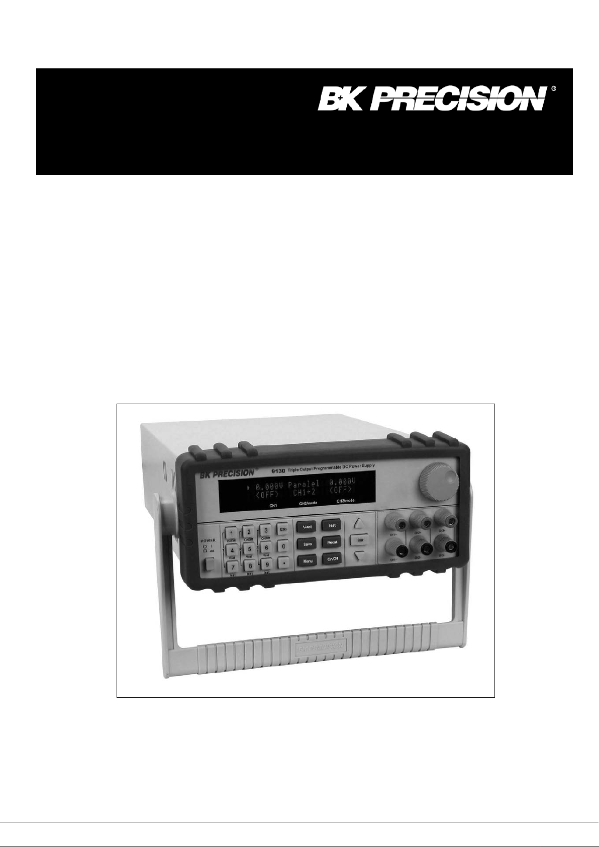
Model 9130
Triple Output Programmable DC Power Supply
Page 2

Safety information
Please review the followin g s af et y precautions before operating our equipment.
General information
The following safety pr ecaut ions should be observed before using this product and any associated
instrumentations.
This product is intended for us e by qualified personnel who recognize shock hazards and are familiar
with the safety precautions required to avoid possible injury. Read an d fo l low all installation, operation,
and maintenance inform at ion carefully before using the product. Re fer to this manual for complete
product specifications.
If the product is used in a manner not specified, the protection provided by the product may be
impaired.
Before performing any ma intenance, disconnect the line cord and all test cables.
Protection from electric shock
Operators of this instrume nt must be protected from electric shock at all t i mes. The responsible body
must ensure that operator s ar e pr evented access and/or insulated from ever y connection point. In
some cases, connections mu s t be exposed to potential human contact.
Under these circumstances personnel must be trained to protect themselves from the risk of electric
shock. If the circuit is capabl e of o per ating at or above 1000 volts, no conducti ve part of the circuit may
be exposed.
Definition of users
Responsible body is the indiv idual or group responsible for the use and ma intenance of equipment is
operated within its specifi cations and operating limits, and for ensur i ng t hat operators are adequately
trained.
This product should only be used as intended. Users must be trained in electr ical safety procedures
and proper use of the instrument . Users must be protect ed from electric shock and contact with
hazardous live circuits.
Service is only to be performe d by qualified service personnel.
Safety symbols and terms
Connect it to safety earth ground using the wire recommended in the user manual.
The symbol on an instrument indicates that the user should refer to the operating
instructions located in the ma nual.
Complies with the essent i al requirements of the European direct ives.
Certification
We certify that this product met its published specifications at time of shipm ent from the factory.
2
Page 3

TABLE OF CONTENTS
1. INTRODUCTION ......................................................................................................................... 5
2. QUICK START .............................................................................................................................. 6
2.1 Front & Rear Panel ........................................................................................................................ 6
2.2 Preliminary Checkout ..................................................................................................................... 7
3. SPECIFICATIONS ...................................................................................................................... 12
3.1 Specifications ............................................................................................................................... 12
3.2 Supplemental Chara ct er ist ic s ...................................................................................................... 13
4. FRONT-PANEL OPERAT ION .................................................................................................... 14
4.1 Front-panel Operation Overview .................................................................................................. 14
4.2 Panel Description ......................................................................................................................... 15
4.3 VFD Description and Wiri ng Diagram .......................................................................................... 15
4.4 Menu Descriptions ....................................................................................................................... 16
4.5 Panel Operation ........................................................................................................................... 17
4.6 Menu Function .............................................................................................................................. 19
5. REMOTE OPERATION .............................................................................................................. 24
5.1 Communication cabl e ................................................................................................................... 24
5.2 Communication between Power Supply and PC ......................................................................... 25
5.3 SCPI Command Over view ........................................................................................................... 26
5.3.1 Common IEEE488.2 commands .................................................................................................................... 26
5.3.2 Essential SCPI Commands ............................................................................................................................ 26
5.3.3 Nonstandard SC PI Commands ...................................................................................................................... 27
5.3.4 Simultaneous Control SCPI Commands (For firmware version 1.66 or above only) .................................... 28
5.4 SCPI Command Desc r iption ........................................................................................................ 30
5.4.1 SCPI Condition Register ................................................................................................................................ 30
5.4.2 SCPI Command Description .......................................................................................................................... 32
6. PV9130 SOFTWARE GUIDE ..................................................................................................... 40
6.1 Introduction ................................................................................................................................... 40
6.2 Installation .................................................................................................................................... 40
6.3 PV9130 basics ............................................................................................................................. 40
6.3.1 Save and Open ............................................................................................................................................... 42
6.3.2 Chart Description ........................................................................................................................................... 42
6.3.3 Status bar ....................................................................................................................................................... 43
6.4 Operation ...................................................................................................................................... 43
6.4.1 Configure the system ..................................................................................................................................... 43
6.4.2 Setting Voltage and C urrent ........................................................................................................................... 44
3
Page 4

6.5 Test sequence generation ......................................................................................................... 44
6.5.1 Quickset ......................................................................................................................................................... 44
6.5.2 Program ......................................................................................................................................................... 45
6.5.2 Go/NG ........................................................................................................................................................... 45
4
Page 5

1. Introduction
Description
The 9130 is a fully programmable triple Output DC Power Supply delivering 0-30V/0-3A on 2
outputs and 0-5V/0-3A on 1 output. Each output is fully floating and outputs can be adjusted
independently or connected in series or parallel to produce higher voltages or currents. The front
panel keys and the control knob provide a convenient means to adjust the voltage and current of a
selected output; enable or disable parallel or series tracking mode; store and recall operating states
or enable/disable individual outputs. The 9130 is ideally suited for applications in Electronic Test,
Production and Service, where multiple independent DC supplies are required and bench space is
at a premium.
Key Features
3 independent, fully programmable and electrically isolated outputs
Series or parallel operation
Display Voltage and Current for of all 3 channels simultaneously
Over Current (OCP) and Over Temperature (OHT) protection
Very compact foot print ( 2U x 1/2)
Bright and easy to read display (VFD technology)
High resolution, accuracy and stability
Output on/off control
Low ripple and low noise
SCPI compatible command set, communicate via USB or RS232 port
Application Software for front panel emulation and simple test sequence generation
50 memory locations for instrument state storage & recall
Convenient data entry via knob or numerical key pad
Rack mount kit available
5
Page 6

2. Quick Start
1
3
5
6
1
2
3
4
5
6
7
This chapter will help you getting acquainted with the front panel operation of this power supply.
2.1 Front & Rear Panel
Front panel
4
2
7
VFD display
Rotary knob
Main power switch
Numerical key pad and “Esc” key
Function keys
Cursor position & Channel Selection keys, “Enter” key
Output terminals
6
Page 7

3
Rear Panel
1 2
4 5 6
1) Terminal block for GND reference and additional negative output terminal
2) AC receptacle
3) Ventilation holes
4) Interface connector for remote control of power supply
5) 110V/220V AC Power selection switch
6) Fuse compartment
2.2 Preliminary Che ckout
The following steps will help you verify that the power supply is ready for use.
1.Check the list of supplied items
Verify that you have received the following items with your power supply. If anything is missing, contact your
authorized B+K Precision distributor.
• Power cord
• Instruction manual
• Calibration Report
• Communication cable
• Software installation disk
7
Page 8
2.Connect the power cord and turn on the power supply
When you turn on the power supply, the front-panel display will light up briefly while the power supply
performs its power-on self-test. All the VFD annunciators will turn on at once. Check for any missing display
segments. In the event that there is no response when you turn on the power supply, refer to section 5 of this
chapter for additional information.
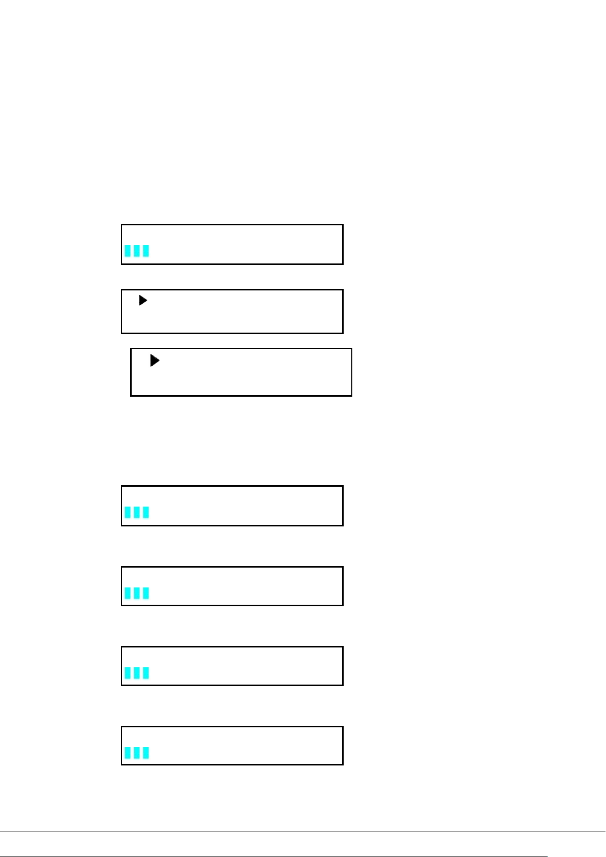
3. System Checkout
At power up, the instrument will automatically perform a self test routine. During this time, the following
should be displayed:
System Test, Please wait!
followed by
0.000V 0.000V 0.000V
<OFF> <OFF> <OFF>
Or:
Note: The first row is the output voltage for channels 1 – 3. The second row will display the on/off state or the
output current of each channel.
In case the self test routine is not successful, you may see one of the following:
If the EEPROM is damaged, the VFD will display the following:
10.000V 11.000V 3.000V
2.000A 3.000A 3.000A
EEPROM Error
If the last operation data which should be stored in the EEPROM was lost you should see
Data Check Error
If the latest data about off-time in EEPROM was lost, the VFD will display
Load Off Time Fail
If the calibration data stored in the EEPROM was lost, the VFD will display
CH X Lost Calibration...
8
Page 9

Note: “X” denotes the channel for which calibration data was lost.
On/Off
On/Off
On/Off
If the calibration data in the EEPROM is corrupted or the factory calibration values are lost, the VFD will display
the following:
Lost Factory Calibration
Note: You will see a “?” on the VFD, in case of any errors are encountered during the self
test routine.
4.Output Verification
The following procedures verify that the power supply outputs the correct voltage and current levels and properly
responds to entries from the front panel.
• Voltage Output Checkout
The following steps verify basic voltage functions without load.
1) Turn on the power supply.
2) Turn on the outputs using the
Note: Flashing voltage values indicates that the power supply is in “Set mode, ‘‘Set mode’’ means that
the VFD display shows the set values for voltage and current. In “meter mode” the display will
indicate the actual output voltage and current.
3) Check that the front-panel voltmeter properly responds to number key entries
Enter a different voltage value and wait a few seconds until the meter mode activates. Verify that the
actual output value voltage is identical to the set value. Also verify that the displayed current value is
close to zero.
4) Ensure that the voltage level can be adjusted from zero to the maximum rated value.
5) Verify channels 2 & 3 according to steps 1) – 4)
key
• Current Output Current
The following steps check basic current functions with a short across the power supply’s output.
6) Turn on the power supply
7) Turn the output off
Press
8) Connect the (+) and (-) output terminals of channel 1 with a short, insulated test lead. Use a wire size
sufficient to handle the maximum current.
9) Set the voltage value with 1V
key to ensure that the outputs are off. (bottom row indicates “OFF”)
10) Turn on the output using the
11) Adjust the current value
Enter a different current value, wait until the instrument is in meter mode, then make sure that the
displayed current value (actual output value) is the same as the set value.
12) Ensure that the current can be adjusted from zero to the maximum rated value.
13) Turn off the power supply and remove the short wire from the output terminals.
key.
9
Page 10
14) Verify channels 2 & 3 according to steps 1) – 8)
5.If the Power Supply Does Not Turn On
Use the following steps to help resolve problems you might encounter when turning on the instrument.
1). Verify that there is AC power applied to the power supply.
Verify that the power cord is firmly plugged into the power receptacle on the rear panel of the power supply.
Make sure the power outlet you are using is working properly and verify that the power supply is turned on.
2). Verify the power-line voltage setting.
Make sure the voltage selector switch is set according to the present line voltage (110VAC or 220VAC).
Change the voltage setting if it’s not correct.
3). Verify that the correct power-line fuse is installed.
Model Fuse Description
9130 Fuse 3.15A T250V(220V AC)
Fuse 6.30A T250V(110V AC)
If the fuse is blown replace it according to the table above.
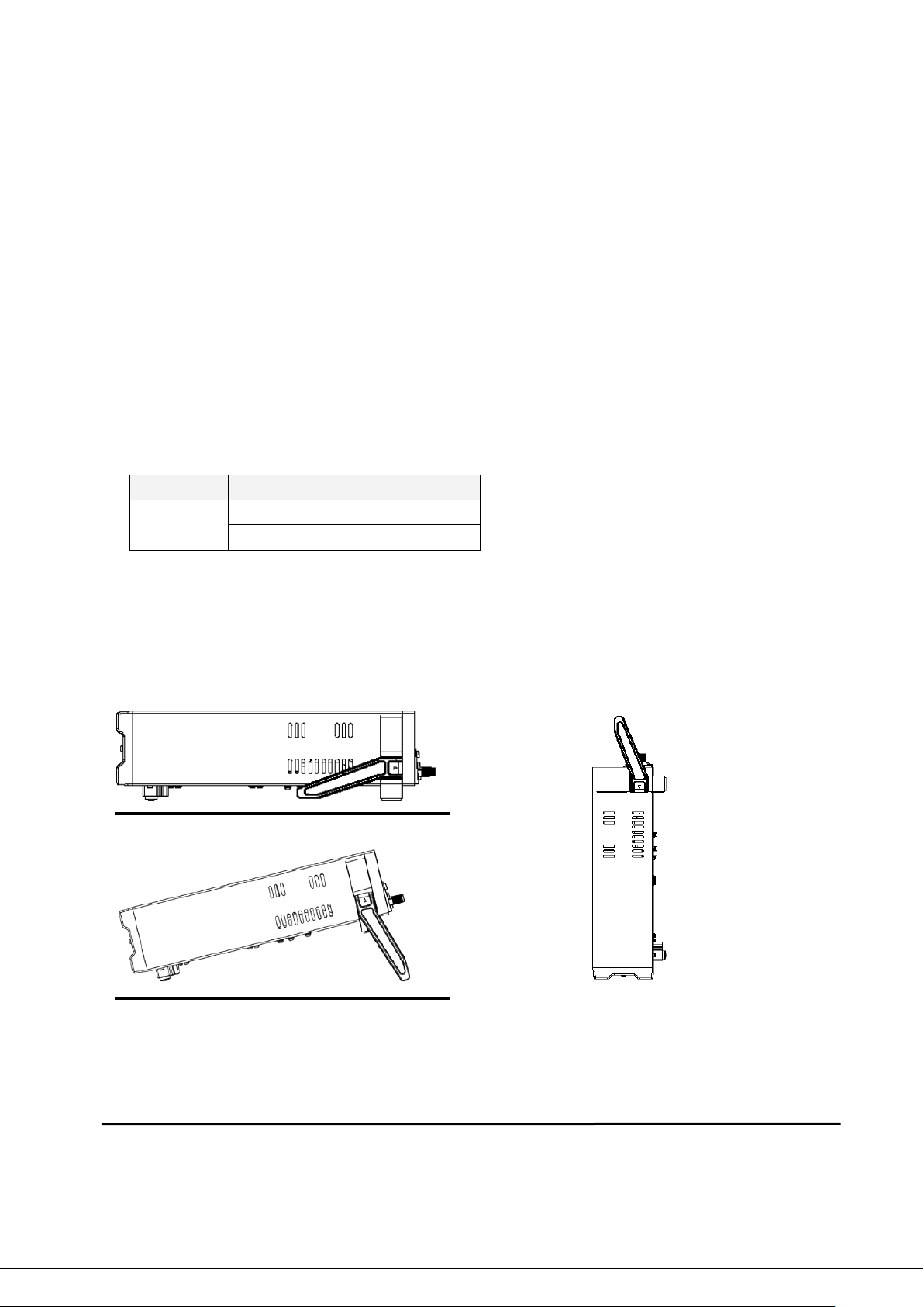
6.To Adjust the Carrying Handle
To adjust the position, grasp the handle on each side and pull outwards, then rotate the handle to the desired
position.
Bench-top viewing positions Carrying position
7. To Rack Mount the Instrument
You can mount the power supply in a standard 19-inch rack cabinet using the IT-E151 rack mount kit.
Note: Remove the carrying handle and the two plastic ears before rack-mounting the instrument. To remove
the handle, grasp the handle on the side, pull outwards and rotate it to a special position where the
10
Page 11

arrow on the handle and the arrow on the plastic ears are in opposite directions. Now you can pull
the handle outwards. After removing the handle, you can remove the two plastic ears with a screw
driver.
11
Page 12

3. Specifications
Resolution
3.1 Specifications
Parameter 9130
Output ratings
Load Regulation
±(%of output+offset)
Line Regulation
±(%of output+offset)
Voltage 0~30V×2, 0~5V×1
Current 0~3A×2, 0~3A×1
LVP* 0~31V×2, 0~6V×1
Voltage ≤0.01%+3mV
Current ≤0.1%+3mA
Voltage ≤0.01%+3mV
Current ≤0.1%+3mA
Programming
Resolution
Readback
Resolution
Programming accuracy
(12 months)
±(%of output+offset)
Readback accuracy
(25 °C ± 5 °C)
±(%of output+offset)
Ripple & noise Voltage
Transient Response Time
Temperature coefficient
(0 °C ~ 40 °C)
±(%of output+offset)
Voltage 1mV
Current 1mA
Voltage 1mV
Current 1mA
Voltage ≤0.03%+10mV
Current ≤0.1%+5mA
Voltage ≤0.03%+10mV
Current ≤0.1%+5mA
Voltage ≤0.03%+10mV
Current ≤0.1%+5mA
Ripple: ≤1mVrms/3mVp-p
Noise: ≤3mVrms
< 500 μs for CH1&2, < 200 μs for CH3
for output to recover to within 75 mV
following a change from 100 mA to 1 A
Readback Temperature
Coefficient
±(%of output+offset)
Tracking Accuracy
Series Operation
Tracking Accuracy
Parallel Operation
Output Timer
Weight 19.8 lbs, (9 kg)
Dimensions 214.5mm(W) × 88.2mm (H) × 354.6mm (D)
Voltage ≤0.03%+10mV
Current ≤0.1%+5mA
Current ≤0.05%+10mA
Voltage ≤0.02%+5mV
Current ≤0.1%+20mA
Time set 1s~999999s
1s
12
Page 13

8.45in(W) x 3.8in(H) x 13.9in(D)
*) LVP : Limit Voltage Protection. Limits the vol tage than can be set either via th e front panel or remote control co mmand.
NOTE: Specifications and information are subject to change without notice. Please visit
current product information.
www.bkprecision.com for the most
3.2 Supplemental Characteristics
State Storage Memory
50 user-configurable stored states
Recommended Calibration Interval
1 year
AC Input Ratings (selectable via switch on the rear panel)
220AV±10%, 47~ 63Hz
110AV±10%~ 47~ 63Hz
Maximum power consumption
Model 9130
Power 750VA
Cooling
Fan cooled
Operating Temperature
0 to 40 °C for max rated output
Storage Temperature
-20 to 70 °C for storage environment.
Environmental Conditions
Designed for indoor use in an installation category II, pollution degree 2 environment. Designed to operate at
maximum relative humidity of 95% and at altitudes of up to 2000 meters.
13
 Loading...