

Page 1
Model: 9120A, 9121A, 9122A, 9123A, 9124, 9150, 9151, 9152, 9153
Single Output Programmable DC Power
USER MANUAL
Supply
Page 2

2
Safety information
Please review the following safety precautions before operating our equipment.
General information
The following safety precautions should be observed before using this product and any associated
instrumentations.
This product is intended for use by qualified personnel who recognize shock hazards and are familiar with the
safety precautions required to avoid possible injury. Read and follow all installation, operation, and maintenance
information carefully before using the product. Refer to this manual for complete product specifications.
If the product is used in a manner not specified, the protection provided by the product may be impaired.
Before performing any maintenance, disconnect the line cord and all test cables.
Protection from electric shock
Operators of this instrument must be protected from electric shock at all times. The responsible body must ensure
that operators are prevented access and/or insulated from every connection point. In some cases, connections
must be exposed to potential human contact.
Under these circumstances personnel must be trained to protect themselves from the risk of electric shock. If the
circuit is capable of operating at or above 1000 volts, no conductive part of the circuit may be exposed.
Definition of users
Responsible body is the individual or group responsible for the use and maintenance of equipment is operated
within its specifications and operating limits, and for ensuring that operators are adequately trained.
This product should only be used as intended. Users must be trained in electrical safety procedures and proper
use of the instrument. Users must be protected from electric shock and contact with hazardous live circuits.
Service is only to be performed by qualified service personnel.
Safety symbols and terms
Connect to safety earth ground using the wire recommended in the user manual.
This symbol on an instrument indicates that the user should refer to the operating instructions
located in the manual.
Certification
We certify that this product met its published specifications at time of shipment from the factory.
Page 3

3
TABLE OF CONTENTS
1. Introduction ............................................................................................................ 4
Description ............................................................................................................................................... 4
Features .................................................................................................................................................... 4
2. Quick Reference ..................................................................................................... 5
2.1 The Front Panel .......................................................................................................................................... 5
2.2 The Rear Panel ......................................................................................................................................... 6
2.3 Preliminary Checkout ................................................................................................................................. 7
1. Check the list of supplied items............................................................................................................ 7
2. Connect the power cord and turn on the power supply ........................................................................ 7
3. Checkout Procedure ............................................................................................................................. 7
1.4 Output Verification ..................................................................................................................................... 8
Voltage Output Check............................................................................................................................... 8
Current Output Check .............................................................................................................................. 9
1.5 If the power supply does not turn On ......................................................................................................... 9
1.5.1 Fuse Replacement ............................................................................................................................ 9
1.6 Adjusting the Carrying Handle ................................................................................................................. 10
1.7 Rack Mounting the Instrument ................................................................................................................. 11
3. Front-panel Operation ........................................................................................ 12
3.1 Front Panel Keys ...................................................................................................................................... 12
Numerical Keys/Secondary Shift Functions........................................................................................... 13
Shift Functions ....................................................................................................................................... 13
Primary Function Keys ........................................................................................................................... 13
Up/Down and Entry key ......................................................................................................................... 13
3.2 Front-panel Operation Overview .............................................................................................................. 14
3.3 Setting the Voltage .................................................................................................................................... 14
3.4 Setting the Current.................................................................................................................................... 14
3.5 Save and Recall Operation ....................................................................................................................... 14
3.6 Menu Operation ........................................................................................................................................ 15
3.6.1 Menu Description .......................................................................................................................... 15
3.6.2 Menu Function .............................................................................................................................. 17
3.7 Output Operation ...................................................................................................................................... 22
3.8 Remote Sense and digital port functions .................................................................................................. 22
3.9 Digital Volt Meter (DVM) ........................................................................................................................ 23
3.10 Milliohm Meter ...................................................................................................................................... 24
4. Remote Operation ................................................................................................ 24
4.1 Serial adapter cables ................................................................................................................................. 25
4.2 Communication between Power Supply and PC ...................................................................................... 26
4.3 SCPI Command Overview ....................................................................................................................... 28
Common IEEE488.2 Commands ........................................................................................................... 28
Essential SCPI Commands ..................................................................................................................... 28
Port Configuration Commands ............................................................................................................... 30
Trigger Command .................................................................................................................................. 30
SCPI Condition Register ........................................................................................................................ 30
4.4 SCPI Command Description .................................................................................................................... 32
Common IEEE488.2 Commands ........................................................................................................... 32
Essential SCPI Commands ..................................................................................................................... 34
Output Commands .................................................................................................................................. 37
List File Commands ............................................................................................................................... 38
Interface Configuration Commands ....................................................................................................... 42
Trigger commands .................................................................................................................................. 43
Calibration commands ............................................................................................................................ 44
5. Specifications ........................................................................................................ 46
5.1 Specifications ........................................................................................................................................... 46
5.2 Supplemental Characteristics ................................................................................................................... 48
Page 4

4
1. Introduction
2
1
Description
Models 9120A, 9121A, 9122A, 9123A, 9124, 9150, 9151, 9152, and 9153 are fully programmable, linear DC
Power Supplies that provide you with clean and reliable power, high resolution and accuracy combined with fast
transient response times and excellent temperature stability. The front panel keys and the control knob provide
a convenient interface for adjusting Voltage and Current, storing and recalling operating states or
enabling/disabling the output. This power supply is suitable for either bench or rack mounted operation. The
912xA is a compact, laboratory grade power supply well suited for applications in design, production or use in
university labs.
Features
Very high accuracy and resolution: 0.1 mV, 0.1 mA
Low ripple and low noise
Fast settling time of <150 μs
5
Convenient data entry via knob or numerical key pad
Over Temperature (OTP) protection
Bright and easy to read display (VFD technology)
Excellent temperature stability
Output on/off control
SCPI compatible command set. Communicate via USB, RS232 or GPIB (model 9123A only) interface
Application Software for front panel emulation and simple test sequence generation
Rack mount kit available
Closed case calibration
Remote Sense Function
Discrete Fault Indica tor/Remote Inhibit (DFI/RI). Can be used to turn off power supplies simultaneously.
digit digital voltage meter and mΩ meter
(DFI available for models 9120A, 9121A, 9122A, 9123A, 9124 only)
List Mode: Generate, store and execute test sequences without the need for an external computer
Page 5
5
2. Quick Reference
3
2
5
1
2
3
4
8
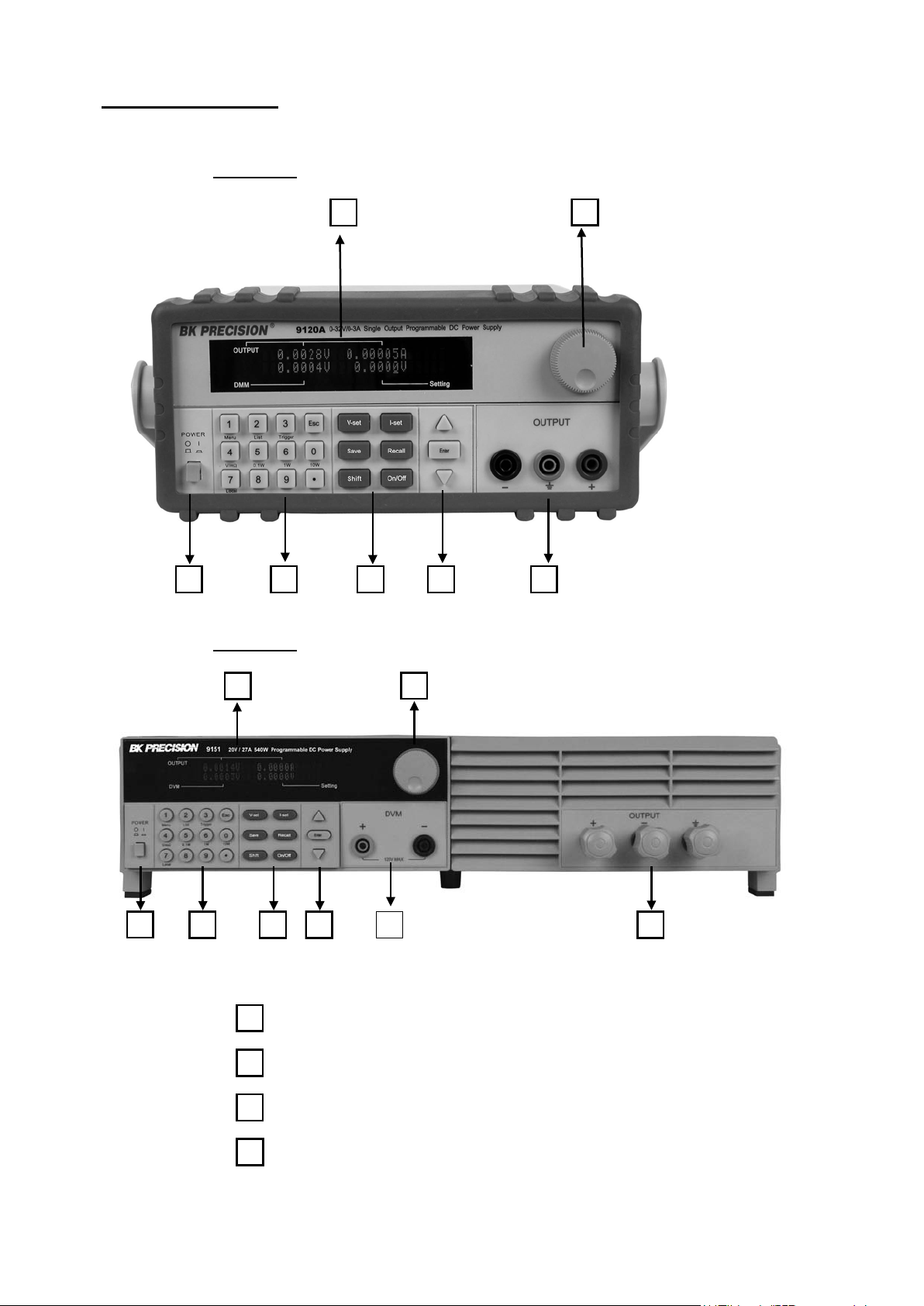
2.1 The Front Panel
For Models: 9120A, 9121A, 9122A, 9123A, 9124
4 5 6 7
For Models: 9150, 9151, 9152, 9153
1 2
1
3 4
6 7
VFD display
Rotary knob
Power switch
Numeric keys, auxiliary. functions
Page 6
6
5
6
7
2
3
4
8
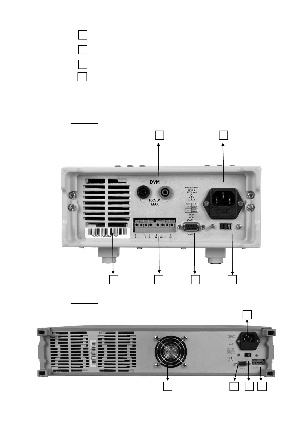
2.2 The Rear Panel
For Models: 9120A, 9121A, 9122A, 9123A, 9124
Function keys
Up/Down keys and “Enter” key
Output term inals
Digital Voltmeter te rminals (For Model 9150, 9151, 9152,
9153)
1 2
3 4 5 6
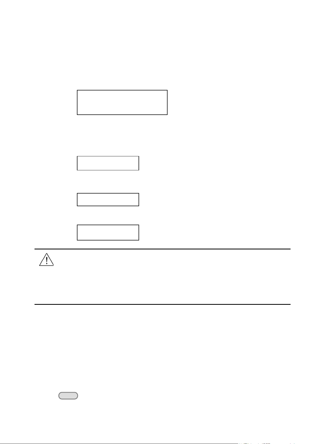
For Models: 9150, 9151, 9152, 9153
5 6
Page 7

7
1
2
3
4
5
6
Digital Voltmeter terminals. (For models 9150, 9151, 9152, and
9153, these terminals are in the front panel)
AC power inlet and fuse compartment
Ventilation holes
Quick connect terminal for Remote sensing and digital port
functions (digital I/O, DFI/RI and ext. trigger)
TTL interface connector for remote control
AC Power selection switch (110 V / 220 V)
2.3 Preliminary Checkout
The following steps help you verify that the power supply is ready for use.
1. Check the list of supplied items
Verify that you have received the following items with your power supply. If anything is missing, contact your
authorized B&K Precision distributor.
- Power cord
- Instruction manual
- Calibration Report
- Communication cable(s)
- Software Installation disk
2. Connect the power cord and turn on the power supply
When you turn on the power supply, the front-panel display will light up briefly while the power supply performs
its power-on self-test. All the VFD annunciators will turn on at once. Check for any missing display segments.
Refer to section 1.5 in this chapter if the power supply does not turn on.
3. Checkout Procedure
At power up, the instrument will automatically perform a self test routine. During this time, the following
should be displayed:
System Test, Please wait!
followed by
0.000V 0.0000A
0.000V 0.000V
Page 8
8
The first row displays the actual output voltage value and current and the state of power supply. The second row
ERR EEPROM
Out on/off
displays the voltage measured by the DVM (on left) and the Set Value for the voltage of the power supply.
To obtain additional information about the instrument, press and hold the SHIFT button during Power Up. On
the display you will see the following:
First row: V/A rating and DVM voltage range
second row: Firmware version and serial number
Press “Esc” to exit the display.
Sourc: XXV XA Meas: XXV
V er : 1.67 SN:5975002002
In case the self test routine is not successful, you may see one of the following:
If the EEPROM was damaged or the latest operation data is lost, the VFD will display:
If the calibration data stored in the EEPROM is lost, the VFD will display
If the latest operating state of the power supply in EEPROM is lost, the VFD will display:
ERROR CAL
Error Config Data
Warning: The power supply is shipped from the factory with a power-line cord that has a plug
appropriate for your location. Your power supply is equipped with a 3-wire grounding type power cord; the
third conductor being the ground. The power supply is grounded only when the power-line cord is plugged
into an appropriate receptacle. Do not operate your power supply without adequate cabinet ground
connection.
1.4 Output Verification
The following procedures verify that the power supply outputs the correct voltage and current levels and properly
responds to entries from the front panel.
Voltage Output Check
The following steps verify basic voltage functions without load.
1) Turn on the power supply.
2) Enable the outputs
Press the key. Notice the CV annunciator turning on.
Page 9

9
Model
Fuse Description (110 VAC)
Fuse Description (220 VAC)
9120A
T2.5A 250V
T1.25A 250V
9121A
T2.5A 250V
T1.25A 250V
9124
T2.5A 250V
T1.25A 250V
9122A
T3.15A 250V
T1.5A 250V
9123A
T3.15A 250V
T1.5A 250V
9150
T10A 250V
T5A 250V
9151
T10A 250V
T5A 250V
9152
T10A 250V
T5A 250V
9153
T10A 250V
T5A 250V
Out on/off
3) Set the voltage value
Set a different voltage value. Make sure that the set value and output value are the same. Also check if the
output current value is zero or close to zero A.
4) Ensure that the voltage can be adjusted from zero to the maximum rated value.
Current Output Check
The following steps check the basic current functionality by shorting the power supply’s output.
1) Turn on the power supply.
2) Disable the output by pressing the . The ON annunciator is turned off.
3) Connect a short across the (+) and (-) output terminals with an insulated test lead. Use a wire size
sufficient to handle the maximum current.
4) Enable the output.
5) Adjust the voltage value to 1.0 volt. Ensure that the CC annunciator is lit (power supply is in CC
operation mode)
6) Adjust the current value. Set a different Current value and check if the actual Current value is the same
as the set Current value. Also verify that the output voltage value is nearly zero.
7) Ensure that the current can be adjusted from zero to the full rated value.
8) Turn off the power supply and remove the short wire from the output terminals.
1.5 If the power supply does not turn On
Use the following steps to help resolve problems you might encounter when turning on the instrument.
1. Verify that there is AC power applied to the power supply.
Verify that the power cord is firmly plugged into the power receptacle on the rear panel of the power supply.
Make sure the power outlet you are using is working properly and verify that the power supply is turned on.
2. Verify the power-line voltage setting.
Make sure the voltage selector switch is set according to the present line voltage (110 VAC or 220 VAC).
Change the voltage setting if it’s not correct.
3. Verify that the correct power-line fuse is installed.
1.5.1 Fuse Replacement
Replace blown fuses according to the table above.
Page 10
10
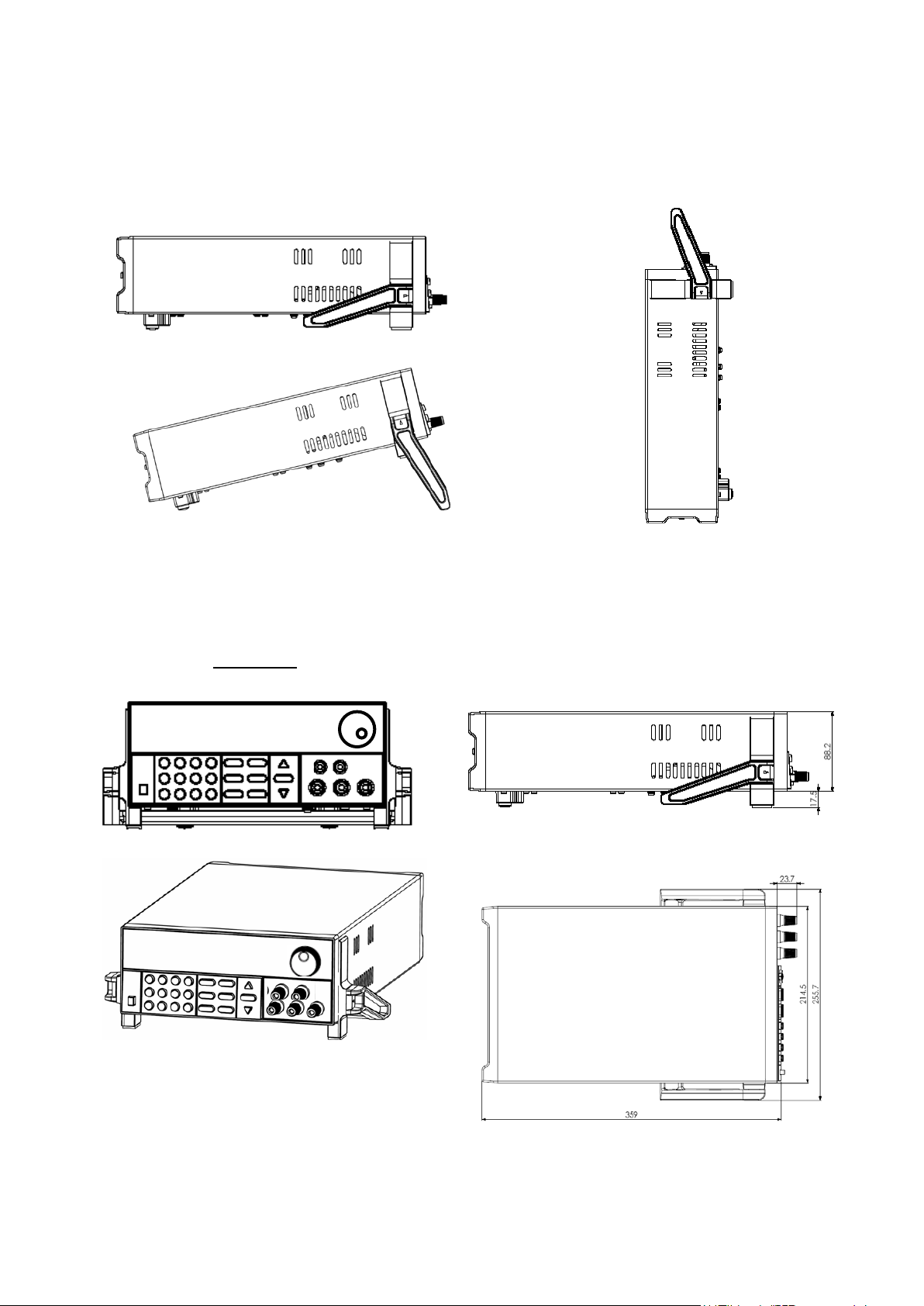
1.6 Adjusting the Carrying Handle
To adjust the position, grasp the handle by the sides and pull outward. Then rotate the handle to the desired
position.
Dimensions:
214.5 mm (W) x 88.2 mm (H) x 354.6 mm (D) all units in mm
For Models: 9120A, 9121A, 9122A, 9123A, 9124
Page 11
11
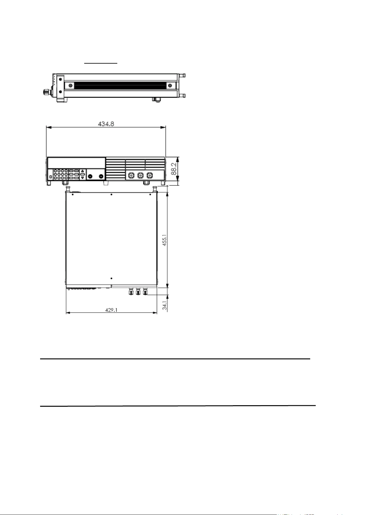
For Models: 9150, 9151, 9152, 9153
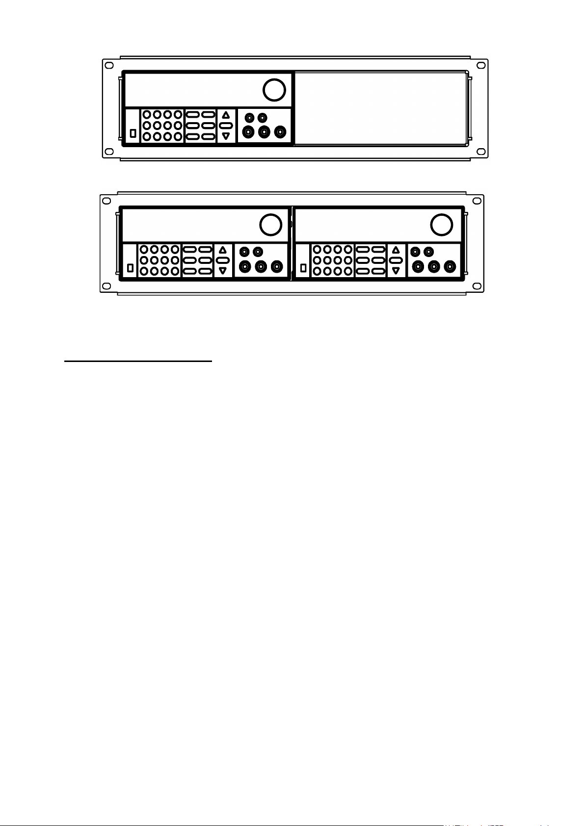
1.7 Rack Mounting the Instrument
You can mount the power supply in a standard 19-inch rack cabinet using the IT-E151 rack mount kit.
Note: Remove the carrying handle and the two plastic ears before rack-mounting the instrument. To
remove the handle, grasp the handle on the side, pull outwards and rotate it to a special position
where the arrow on the handle and the arrow on the plastic ears are in opposite directions. Now you
can pull the handle outwards. After removing the handle, you can remove the two plastic ears with a
screw driver.
Page 12
12
To rack mount a single instrument, order rack mount kit IT-E151
To rack mount two instruments (models 9120A, 9121A, 9122A, 9123A, 9124 only) side-by-side,
order rack mount kit IT-E151, In this case you don’t need to use the front cover panel.
3. Front-panel Operation
So far we have covered the quick start chapter which briefly introduced the front panel operation and how to
check basic voltage and current functionality. This chapter describes in detail how to operate the instrument
manually via the front-panel keys.
This chapter is divided into the following sections:
Front-Panel Operation Overview
Setting the Voltage
Setting the Current
Save/Recall Operation
Menu Operation
On/Off Operation
Remote Sense and digital port functions
mΩ Meter
Digital Voltage Meter
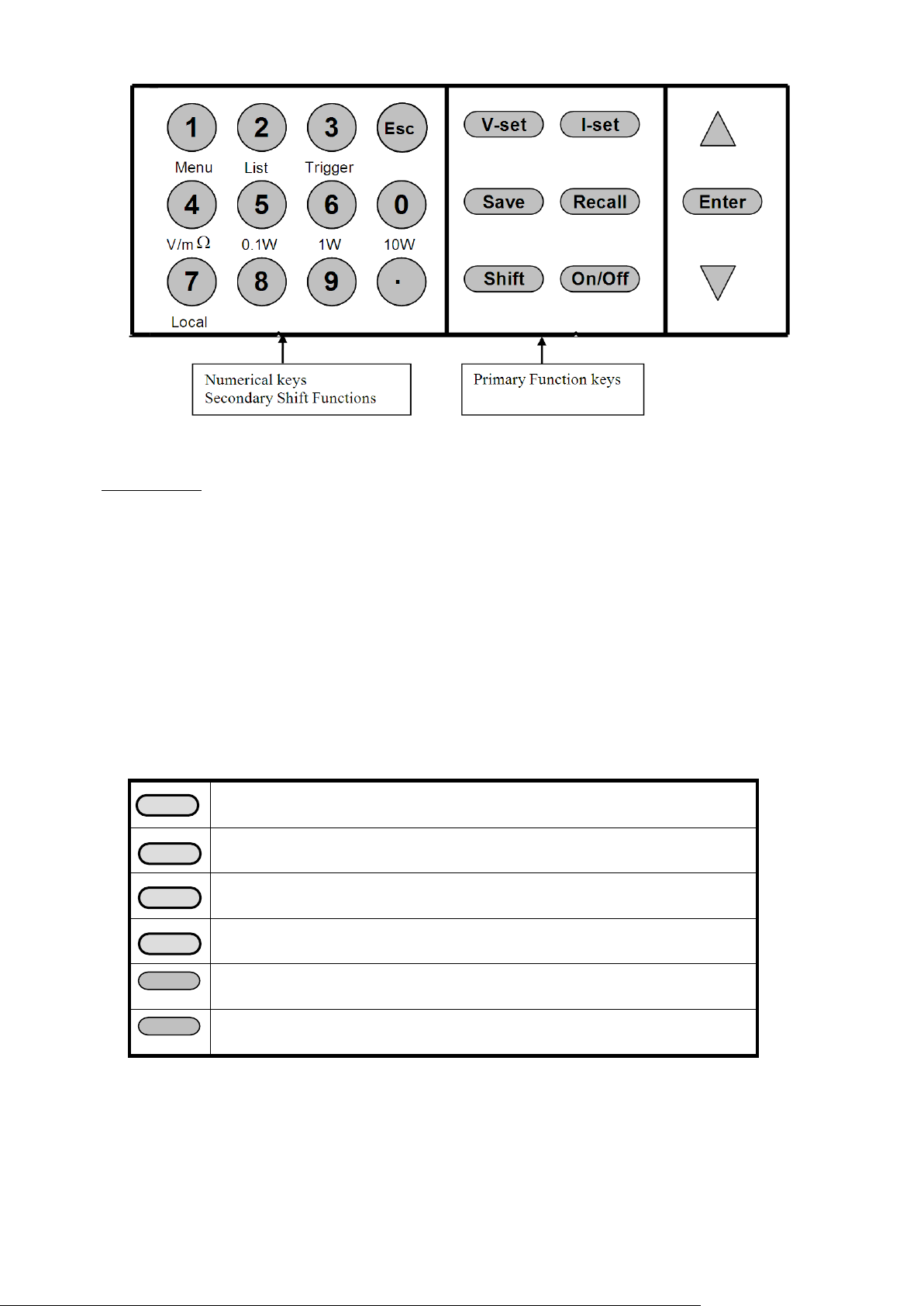
3.1 Front Panel Keys
Page 13
13
On/Off
Shift
Numerical Keys/Secondary Shift Functions
Shift Functions V/mΩ: Toggl e betw een D VM and mΩ Meter mode
0.1 W: Set the range of the mΩ Meter to 0.1 W
1 W: Set the range of the mΩ Meter to 1 W
10 W: Set the range of the mΩ Meter to 10 W
Menu Set the parameters of the power Supply
List Generate programs in List Mode
Trigger Generate a single trigger pulse (when configured for Immediate mode)
Local Enable front panel operation when in remote mode
0 – 9 Numerical keys for direct entry of values
Primary Function Keys
Set the voltage value
Set the current value
Save the current operating data to internal memory
Recall operating data from internal memory
Set the output state of the power supply
Use to access secondary functions
Up/Down and Entry key
▲:Up key
Page 14

14
▼:Down key
V-setV-set
Enter
Save
ENTER
9
0
Out on/off
I-Set
Enter
Enter: Press to confirm numerical entries
3.2 Front-panel Operation Overview
1) The power supply at shipment is preconfigured for front-panel operation. At power-on, the power supply
will automatically start up in front panel operation mode.
2) When the power supply is in remote operation mode, the front-panel is disabled. You can revert to Local
mode, by pressing the Local button or by sending the appropriate SCPI command. Toggling between
front-panel and remote operation modes will not result in any change of the output parameters.
3) The output of the power supply can be enabled or disabled from the front panel by pressing
the key. When the output is on, the CV or CC annunciator will turn on.
4) The VFD annunciators display the present operating status of the power supply. At power up, the following
is displayed: The top row shows the actual output voltage and output current value and the state of the
power supply. The second line shows the voltage value as measured by the DVM and the Set value of the
Voltage. The bottom right field is also used to display the Current Set Value, the Menu parameters and the
Ohm meter range.
3.3 Setting the Voltage
The Voltage can be adjusted from 0V to the maximum rated voltage of each model. There are 2 ways to set the
constant voltage value.
Solution1:
Press the ▲ and ▼ keys or the knob to change the value of the least significant digit
Solution2:
1. Press
2. Use the numeric keys to and confirm your entry by pressing
3.4 Setting the Current
The Current output is adjustable from 0A to the maximum current value of each model.
1. Press
2. Enter a numerical value or use the ▲and ▼keys to change the current value
3. Press to confirm the value
3.5 Save and Recall Operation
You can store up to 50 different operating states in memory locations 1 through 50. Each operating state
includes a constant voltage value, constant current value, maximum output voltage value and voltage step value.
To save a setting:
Set the desired Voltage and Current value
Press the save
key. Use the knob to scroll to one of the memory locations 1 – 50. Press
Page 15

15
to assign and store the current settings to the selected memory location
ENTER
ESC
MENU
Config
Config Init.
Return to the factory default setup value.
Out Recall
Set the Power ON/OFF state after power up.
On
“Remembers” and restores the Power ON/OFF state of the
Off<Default>
Disable this function.
PWR-ON Recall
Recall operating parameters of power supply after power up
On
“Remembers” and restores the operating parameters of the
power supply (voltage, current settings..) before power was
turned off.
Off<Default>
Disable this function.
Key Sound Set
Keypad sound setting.
On<Default>
Enable key sound.
Off
Disable key sound
Knob Lock Set
Enable/disable the rotary knob.
On
Lock the rotary knob.
Off< Default >
Unlock the rotary knob.
Remote Sense
Setup voltage measurement Mode.
On
The power supply will measure the input voltage at the
remote sense connector.
Off< Default >
The power supply will measure the input voltage at the
ShortCut Call
Shortcut of the recall function
On
Enable this function
Off<Default>
Disable this function
Meter Rate
Set the update speed of the power supply meter
High
High speed
Low <Default>
Low speed
Baudrate Set
Baudrate 4800 <Default>
Baudrate 9600
Baudrate 19200
Baudrate 38400
Comm. Parity
Configure the parity bit.
ENTER
To recall a setting:
Press the Recall key. Use the knob to scroll to the memory location where the settings you want to recall are
stored. Press
to recall and activate those settings
You can also use the SCPI command:*SAV *RCL to save and recall respectively.
3.6 Menu Operation
3.6.1 Menu Description
Press Shift :Menu to enter menu mode. The menu parameters will be displayed in the bottom right field of the
display. Use the ▲ and ▼ keys to scroll through the menu list and press to select a menu and view the
parameters. Press
to return to the higher level menu and to return to the main operating mode.
power supply before power was turned off.
front panel connector.
Page 16

16
None< Default >
Even
Odd
Address Set
Set the communication address (range from 0 to 30)
Address=**
Port Mode
Select mode of digital port
Trigger< Def >
RI/DFI
Note: DFI is not available for models 9150, 9151, 9152,
DIGITAL I/O
Note: Digital output not available f or models 9150, 9151,
9152, 9153
Trig Source
Setting the trigger mode
Immediat<Def>
Shift
Trigger
keys will generate a
trigger pulse
External
Ext. Trigger signal is applied to the digital port in the rear
panel.
Bus
Remote command trigger mode.
RI Mode
Configure the Remote Inhibit (RI) mode
Off< Default >
Disable this function
Latching
Live
DFI Source
Configure the Discrete Fault Indicator (DFI) mode
Off< Default >
QUES
Question Bit
OPER
Operation Bit
ESB
Event State Bit
RQS
Require Bit
Key Lock Set
Setting keypad password.
Press
Enter
directly to disable the key lock function.
Password= ****
Exit
System Set
Max Volt. set
Set the Maximum Voltage.
Max= ****
Step Volt Set
Set the voltage step
Step=****
Exit
List Set
Configure list files
Call ListFile
Recall list operation file.
Recall *
Edit ListFile
Edit list operation file.
Continuous
Once
Repeat
Step
Once
Repeat
Save Mode Set
Users can allocate 4 types of memory space to save the list file.
8 X 25 Steps
4 X 50 Steps
9153
Pressing
+
Note: Not used for models 9150, 9151, 9152, 9153
Page 17

17
2 X 100 Steps
1 X 200 Steps
Exit
Out On Timer
Output timer. If Timer State is set to ON, power supply output will turn off after the
timer elapsed.
Timer State
Setting POWER ON timer state
On
Enable Output Timer. Output will turn off after value set
in menu “Timer Set” counted down to zero.
Off< Default >
Timer Set
Setting time of POWER ON timer.
Timer= **S
Exit
Exit
Shift
MENU
ENTER
ENTER
ENTER
3.6.2 Menu Function
ShortCut Recall
This parameter enables a Shortcut version of the Recall functionality available by pressing the Recall button ( see
3.5)
To enable this function, do the following:
1. Press
+
2. Press ▲, ▼ to scroll to ShortCut Recall then press
3. Press ▲, ▼to turn this feature On,press
When Config is displayed, press
to confirm.
4. Press Esc twice to exit from the menu
Now you can conveniently recall up to 9 settings by simply pressing one of the corresponding number keys 1 – 9.
The setting previously stored at that location, (using the Save function), will be retrieved and activated. If the
selected location is empty, EEPROM ERROR will be displayed.
Setting the Baud Rate (>BAUDRATE)
This parameter configures the baud rate for serial communication. Possible values are 4800, 9600, 19200 or
38400. When operating the power supply in remote mode, make sure that you configure identical baud rate
settings for the power supply and the computer. The default setting is 4800.
Setting Addr ess (>ADDRESS)
With this parameter, it is possible to address each instrument. The address range is 0 to 30. The default address
is zero. This is useful when multiple instruments of the same model are connected to a PC for remote
connection. The address is used to identify the instrument to control.
Port Mode
A 4-pin connector in the rear panel is provided for digital input and output signals. For models 9150, 9151,
9152, and 9153, it is a 2-pin connector. This digital port can be configured to provide Fault/Inhibit, External
Trigger or Digital I/O functions. The signal level is TTL.
Page 18

18
TRIGGER: Pins 1 and 2 can be used to apply external trigger sources to the power supply. These pins can
Mode
Trigger
RI/DFI
DIGITAL I/O
1 (INH)
Trigger in
Inhibit Input
Digital Input
2 (GND)
GND
GND
GND
3 (FLT)
Not Used
Fault Indicator Output
Digital Output
4 (GND)
Not Used
GND
GND
Mode
Pin
Trigger
RI
DIGITAL I/O
1 (TRIN)
Trigger in
Inhibit Input
Digital Input
2 (GND)
GND
GND
GND
Shift
also be used to control the list operation
RI/DFI: The Inhibit Input pin can be used to control the output state of the power supply (RI function).
The Fault Output pin (DFI function) can be used to indicate internal faults of the power supply.
NOTE: The Fault indicator function (DFI) is only available for models 9120A, 9121A, 9122A, 9123A, and
9124.
DIGITAL I/O: Read and control output and input state of the 2 available pins. For models 9150, 9151, 9152,
and 9153, only digital input is available.
For Models: 9120A, 9121A, 9122A, 9123A, 9124
Pin
For Models: 9150, 9151, 9152, 9153
Trigger Operation
The power supply supports 3 different trigger modes. Immediate, External and Bus. Configure one of the trigger
sources before performing trigger operation.
• Trigger Key:
When this function is enabled, you can generate an immediate trigger pulse by pressing
Trigger.
• External trigger signal (TTL):
When this function is enabled, the power supply can be triggered with a TTL pulse applied to pin 1 of
the terminal connector in the rear. The TTL on pulse width should be at least 5 ms.
• Bus:
When this function is enabled, you can trigger the power supply by sending a *TRG or TRIgger
command to the power supply
Remote Inhibit (RI) - Input
Used to turn off the output of the power supply. Can be used to turn off several power supplies simultaneously.
Page 19

19
The RI input has 3 modes: LATCHING, LIVE and OFF
LATCHING When the TTL signal at the RI port transitions from TTL High to Low, the output of the power
supply will turn off.
LIVE The output state of the power supply changes according to the signal level applied to the RI port.
If the level is TTL high, the power supply output is on; if the level at the RI port is TTL Low,
the output of the power supply is off.
OFF The signal applied to the RI port does not affect the output state of the power supply.
Discrete Fault Interupt (DFI) - Output
NOTE: Available for models 9120A, 9121A, 9122A, 9123A, and 9124A only.
Used to indicate that a fault has occurred in power supply.
The DFI function can be activated by state changes of the QUES, OPER, ESB, RQS bits
QUES: The output level of DFI reflects the state of the QUES bit. When the QUES bit is 1, the DFI output
goes to a low level. When QUES bit is 0, DFI output goes High
OPER: The output level of DFI reflects the state of the OPER bit.
ESB: The output level of DFI reflects the state of the ESB bit.
RQS: The output level of DFI reflects the state of the RQS bit.
OFF: The output level of the DFI port remains high.
KEY LOCK
It is possible to set a password to lock the function keys. After setting the password, all the function keys on the
front panel will be locked except the OUT On/Off key. You must enter the correct password to enable the keys
again. If you don’t want to lock the function keys and you selected the “>KEY LOCK” menu, simply press the
“Enter” key. Do NOT enter any numbers.
When shipped from the factory, no password is set and the function keys are unlocked. The start bit of your
desired password should not be 0.
List Set
This mode allows you to create a sequence of steps, store it into the power supply’s non volatile memory and
execute it. The input parameters for generating a list include the name of the list file, the input steps (no more
than 200 steps), the step time (the minimum is 1 mS) and the value of each step. The list file can be stored in
ROM with a capacity of 4K from where it can be recalled. This memory area is divided into four areas 1,2,3,4.
Each area can store a certain amount of groups, and each group has an assigned maximum capacity according to
the table below:
Page 20

20
Memory area
Number of groups/ area
Capacity/group
1 1 4KByte
2 2 2KByte
3 4 1KByte
4 8 512 Byte
Shift
MENU
Enter
Enter
Enter
Shift
Menu
Enter
Enter
Enter
Enter
Enter
Enter
Enter
Enter
Enter
Enter
Enter
Enter
Enter
Esc
Example: Group C can store 4 groups, each group has a maximum capacity of 1KByte.
The power supply executes a list in CONTINIOUS or Step mode. In CONTINIOUS mode, the power supply will
start executing the list once. As soon as a trigger signal is received, it will wait until the next trigger signal is
received.
Before you edit the list file, set the trigger source in the menu to “immediate”.
Example:
1) Press
2) Press up or down key to select “Config”, press
3) Press up or down key to select “Trig Source”, press
4) Press up or down key to select “Immediat”, press
+
to confirm.
to confirm.
to confirm.
Operation:
Generate file: 2 cycles, continuous mode
1) Press
2) VFD displays Config, press▼to select List Set,press
3) VFD displays Call ListFile, press▼to select Edit ListFile, press
4) VFD displays Continuous, press
5) VFD displays Repeat, press
6) VFD displays Second, Select ms then press
+
into menu operation.
to confirm.
to confirm.
to confirm.
to confirm
to confirm
7) VFD displays List Count= _, press numeric key or move the rotary knob, set number of cycles (in this
example, count is 2), press
to confirm.
8) VFD displays 1th=*.****V, press numeric key or move the rotary knob, set the maximum
voltage, press
to confirm.
9) VFD displays 1th=*.****A, press numeric key or move the rotary knob, set the maximum
current, press
to confirm.
10) VFD displays 1th=*mS, press numeric key or move the rotary knob, set delay time, press
to confirm.
11) VFD displays 2th=*.****V, press numeric key or move the rotary knob, set the maximum
voltage, press
to confirm.
12) VFD displays 2th=*.****A, press numeric key or move the rotary knob, set the maximum
current, press
to confirm.
13) VFD displa ys 2th=*mS, press numeric key or move the rotary knob, set delay time, press
to confirm.
14) VFD display Store File_, press numeric key or move the rotary knob, set the register number (1 to 8),
press
to confirm.
15) Press
Execute file
two times to escape menu operation.
Page 21

21
16) Press
Shift
List
Shift
Trigger
Shift
List
Esc
Shift
List
Shift
Trigger
Shift
List
TriggerTrigger
Trigger
Trigger
Trigger
Trigger
Trigger
Trigger
Trigger Trigger
file. Press
+
+
to set the list file, th en press
to stop.
+
to run the list
If you have created several list files, you can call the list file that you n eed by “Call ListFile” function in the
menu. Press
+
two times to exit menu operation. And then press
to run the file that you called. Press
+
+
to stop running.
to set it, press
Continuous mode: Once the trigger signal is received, the programmed list will be executed once. Once
finished, the instrument will pause until the next trigger signal is received.
Step mode: The power supply will advance to the next step only after it receives a trigger signal.
(Note: In this mode, list step timing parameter will not be prompted for user input or it will be ignored if
controlled with remote commands because the delay between steps will be dependent on trigger instead.)
Digital I/O
When the digital port of the power supply mode is in DIGITAL I/O mode and the power supply is configured for
remote operation, you can send SCPI command (DIGital:INPut[:STATe?] and DIGital:OUTPut[:STATe?])to
read and set the state of the output and input port.
NOTE: Digital output is not available for models 9150, 9151, 9152, and 9153.
Page 22

22
3.7 Output Operation
On/Off
+S
-
S
+
-
INH GND FLT GND
+
-
TRIN GND
For front panel operation, press
control mode, you can send SCPI command (OUTPut ON|OFF) to change the state of output.
to enable/disable the output. If the power supply is in remote
3.8 Remote Sense and digital port functions
8 pin connector in rear panel (Models 9120A, 9121A, 9122A, 9123A, 9124)
4 pin connector in rear panel (Models 9150, 9151, 9152, 9153)
+S,-S Remote sense pins
Remote voltage sensing is used to maintain good regulation at the load and reduce the degradation of regulation
that would occur due to the voltage drop in the leads between the power supply and the load. By connecting the
supply for remote voltage sensing, voltage is sensed at the load rather than at the supply's output terminals. This
will allow the supply to automatically compensate for the voltage drop in the load leads and improve regulation.
You must set remote sense mode before you start remote test function.
+,- Output pins
For Models 9120A, 9121A, 9122A, 9123A, 9124: These pins are identical to the output terminals in the front.
For Models 9150, 9151, 9152, 9153: These pins are the same as remote sense pins.
INH Inhibit Input pin
This pin has multiple functions:
a) When “Port Mode” in the menu is set to “Trigger”, “INH” pin is configured as trigger input. For models
9150, 9151, 9152, and 9153, “TRIN” pin is configured as trigger input.
b) When “Port Mode” in the menu is set to “RI/DFI”, “INH” pin can be used to turn the power supply output
on/off. For models 9150, 9151, 9152, and 9153, “TRIN” pin is used instead.
INH can be configured in 3 ways:
Page 23

23
LATCHING: When the level of INH port changes from high to low, the output of power supply turns off.
+
_
DVM
DUT
LIVE: The output state of power supply changes according to the level of the INH port. If the level
of INH is TTL High, the output is on. If the level at pin INH is TTL Low, the output of the
power supply is off.
OFF: The level state of INH does not affect the output state of the power supply.
c) When “Port Mode” in the menu is set to “DIGITAL I/O”, “INH” pin functions as a digital inpu t pin. For
models 9150, 9151, 9152, and 9153, “TRIN” pin is used for digital input. For digital output, “FLT” is used.
Digital output is not available for models 9150 to 9153. The status of the pin can be read via SCPI command.
FLT: Fault Output pin
(Available for models 9120A, 9121A, 9122A, 9123A, 9124 only)
This pin has multiple functions:
a) When “Port Mode” in the menu is set to “Trigger”, FLT has no function.
b) When “Port Mode” in the menu is set to “RI/DFI”, the FLT pin can be used to determine the reason of a power
supply fault.
The status of FLT can be derived from bits QUES, OPER, ESB, RQS or it can be disabled
QUES: The output level of FLT reflects the state of the QUES bit. When the QUES bit is 1, FLT output a
Low signal, otherwise, if QUES bit is 0, FLT goes High.
OPER: The output level of FLT reflects the of the OPER bit.
ESB: The output level of FLT reflects the state of the ESB bit.
RQS: The output level of FLT reflects the state of the RQS bit.
OFF: The output level of FLT remains high.
c) When “Port Mode” in menu is set to “DIGITAL I/O”, FLT functions as an output pin. The status of the port
can be programmed via SCPI command.
3.9 Digital Volt Meter (DVM)
The power supply provides a built-in Digital Volt meter which can measure DC volts in a range from 0 - 40V.
The connectors are in the rear panel. The voltage value is displayed on the bottom left field of the display.
To measure voltages, connect the leads as shown here:
Page 24

24
Shift
Shift
Shift
Measurement range
0.1 W
1 W
10 W
Test voltage (Output)
1 V
3.3 V
10 V
+
_
DV M
+
_
SUPPLY
Load
By default, the power supply is in DVM mode. Press
and mΩ Meter mode.
followed by V/mΩ to toggle between Voltmeter
3.10 Milliohm Meter
The instrument is also equipped with a Milliohm Meter which can accurately measure resistance up to 10 Ω.
To protect the resistor, make sure to select an appropriate power range before connecting it to the power supply.
To measure resistance, connect the resistor as shown below:
POWER
To measure resistance:
1) Enable Ohmmeter mode: Press
2) Press
measuring.
followed by 0.1 W /1 W /10 W to select an appropriate range for the resistor you are
followed by V/mΩ(Display will show ---.—mΩ Range 0.1 W)
4. Remote Operation
The DB9 TTL interface connector on the rear panel of the power supply can be connected to a RS-232, USB or
Page 25

25
GPIB (model 9123A only) interface via a serial converter cable. This chapter describes how to use a computer to
PC Load
IT-E131 communication cable
COMPUTER
INSTRUM ENT
RX
TX
IT-E131 ISOLATED
COMMUNICATION CABLE
TTL(5V)RS232 I SOLATION
859666668889942311
IT
COMPUTER
INSTRUM ENT
RX
TX
IT-E131 ISOLATED
COMMUNICATION CABLE
TTL(5V)RS232 I SOLATION
859666668889942311
IT
Power
supply
PC
PC Load
IT-E131 communication cable
COMPUTER
INSTRUM ENT
RX
TX
IT-E131 ISOLATED
COMMUNICATION CABLE
TTL(5V)RS232 ISOLA TION
859666668889942311
IT
COMPUTER
INSTRUM ENT
RX
TX
IT-E131 ISOLATED
COMMUNICATION CABLE
TTL(5V)RS232 ISOLA TION
859666668889942311
IT
Power
supply
PC
IT-E132 communication cable
control the output of the power supply.
4.1 Serial adapter cables
RS232 to TTL serial Converter cable IT-E131
The DB9 interface connector on the rear panel of the power supply provides a TTL level interface. Use the
communication cable (IT-E131) to connect the DB9 interface connector of the power supply to the RS-232
interface connector of the computer
Note: It is not possible to connect the DB9 TTL connector on the power supply’s rear panel
supply via a standard RS232 cable to a PC’s RS232 port.
USB to TTL serial Converter cable IT-E132
The DB9 interface connector on the rear panel of the power supply provides a TTL level interface. Use the
communication cable (IT-E132) to connect the DB9 interface connector of the power supply to the USB
interface connector of the computer.
Note: Before you can use the USB communication cable, you must install the USB driver which
can be found on the included installation disk. The driver can also be downloaded at
www.bkprecision.com
Page 26

26
GPIB to TTL adapter IT-E135 (Model 9123A only)
The DB9 interface connector on the rear panel of the power supply provides a TTL voltage level interface. Use
the communication adapter IT-E135 to communicate via GPIB
PC
Connect this
side to your
computer’s
GPIB
interface
(GPIB cable
not included)
Power Supply
Connect this
connector to
DB9 TTL
connector of
power supply
(serial cable
included)
Connect external
AC power
adapter
(included)
Recommended power up sequence:
Connect the IT-E135 adapter to your computer and to the power supply as indicated in the above figure. Connect
the external power adapter. Both TX and RX LED should be lit (provided the power supply is turned off)
Turn on power supply. The TX and RX LEDs will turn off
For maximum throughput, set the baudrate to 38400. Set parity to NONE (default setting). Set address to the
desired GPIB instrument address.
Note: The RX LED and TX LEDs will flic ker to indicate activity on the GP IB bus. The RX LED indicates a
write command (from controller ’s perspective), the TX LED will indicate data transmission from power supply
to GPIB controller.
4.2 Communication between Power Supply and PC
Before putting the instrument into remote operation, make sure that the baud rate, parity bit and communication
address settings on the power supply and computer side are identical, otherwise communication will not be
possible.
1. Address Range is 0 to 30. Default setting is 0.
2. Baud rate: 4800,9600,19200 and 38400 are selectable, default setting is 9600
3. Parity and Data bits: None/8 bits (default setting)
4. Stop bits:1 (fixed)
5. Start Bits: 1 (fixed)
Even/8 bits
Odd/8 bits
Page 27

27
Parity=None
Parity=Odd,
Data Frame Format
Start
Bit
Start
Even
Bit
End of String character is ’\n’ (0x0a)
DB9 Interface Details
8 Data Bits
8 Data Bits
Stop
Bit
Parity
Bit
Stop
Bit
The DB9 connector in the rear panel of the power supply provides a TTL level signal .It can be connected to a
standard PC interface via the IT-E131, IT-E132 or IT-E135 isolated converter/adapter.
Flow Control
There are no hardware flow controls for sending and receiving commands to the power supply.
The average time it takes to both send and receive every command is approximately 200ms. In
the case of more complex commands, more time may be required to complete transmission.
Note: Configuration of address parameter
Communication via RS232 and USB: Setting of the address is optional. It is not required to
communicate with the instrument. The address can be set from the front panel and is stored in non
volatile memory. This feature is useful when communicating via USB, and connecting several
instruments, e.g. via a USB hub. In this scenario, Windows assigns a virtual COM port to each
device which is unknown prior to establishing communications with the instrument (could be
different each time). In this case, the user can correlate each virtual COM port randoml y assigned
by Windows with a user defined address.
Communication via GPIB: Setting of the address value is mandatory and corresponds to GPIB
instrument address according to GPIB/IEEE-488 conventions. Valid values are 0 – 30.
Page 28

28
4.3 SCPI Command Overview
Common IEEE488.2 Commands
*CLS
*ESE
*ESE?
*ESR?
*IDN?
*OPC
*OPC?
*PSC
*PSC?
*RST
*SRE
*SRE?
*STB?
*TRG
*SAV
*RCL
Essential SCPI Commands
SYSTem
:ERRor[:NEXT]?
:VERSion?,
:ADDRess?
:REMote
:LOCal
:RWLock
STATus
:QUEStionable
[:EVENt]?
:CONDition?
:ENABle <VALUE>
:ENABle?
:OPERation
:[EVENt]?
: CONDition?
:ENABle <VALUE>
:ENABle?
Calibration Command
CALibration
:SECure
[:STATe] {<ON|OFF>,<quoted code>}
[:STATe]?
:VOLTage
:LEVel {<level> }
[:DATA] {<numeric value>}
:CURRent
:LEVel {<level> }
Page 29

29
[:DATA] {<numeric value>}
:DVM
:LEVel {<level>}
[:DATA] {<numeric value>}
:SAVe
:INITital
Output Commands
OUTPut
[:STATe] {<bool>}
[:STATe]?
:TIMer
[:STATe] {<bool>}
[:STATe]?
:DATA {<timer>}
:DATA?
[SOURce:]
MODE {<FIXed|LIST|DRM>}
MODE?
VOLTage
[:LEVel] {<n>}
[:LEVel]?
:PROTection
:STATe {<bool>}
:STATe?
[:LEVel] {<n>}
[:LEVel]?
CURRent
[:LEVel] {<n>}
[:LEVel]?
LIST
:MODE {<mode>}
:MODE?
:STEP {<step>}
:STEP?
:COUNt {<n>}
:COUNt?
:CURRent
[:LEVel] {<n>,<n>}
[:LEVel]? {<n>}
:VOLTage
[:LEVel] {<n>,<n>}
[:LEVel]? {<n>}
:WIDth {<n>,<n>}
:WIDth? {<n>}
:NAME {<string code>}
:NAME?
:AREA {1|2|4|8}
:AREA?
:SAVe {1|2|3|4|5|6|7|8}
:RCL {1|2|3|4|5|6|7|8}
:UNIT {SECOND, MSECOND}
Input Measure Command
MEASure
[:SCALar]
Page 30

30
:VOLTage[:DC]?
BIT
Signal
Meaning
Operation status register
2
UNR
Quest condition register
The output of the power supply is unregulated.
3
DDE
Standard event status register
Device-dependent error. Data stored in register is missing or error occurs in
:CURRent[:DC]?
:POWer[:DC]?
:DVM[:DC]?
:RESistance[DC]?
Port Configuration Commands
[SOURce:]
SYSTem
: SENSe [:STATe] {<bool>}
[:STATe]?
PORT
:FUNCtion {<TRIGger|RIDFi|DIGital>}
: FUNCtion?
RI
:MODE {<OFF|LATChing|LIVE>}
:MODE?
DFI
:SOURce {<OFF|QUES|OPER|ESB|RQS>}
:SOURce?
DIGital
:OUTPut[:STATe] {<bool>}
:INPut[:STATe]?
SENSe
:RESistance:
:RANGe {LOW | MIDdle | HIGH>}
:RANGe?
Trigger Command
TRIGger
[:IMMediate]
:SOURce {<source>}
SCPI Condition Register
You can obtain the state of the power supply and read parameters from the operation register. The different states
of the power supply can be read from 7 condition registers. These registers are status byte register, standard event
register, quest condition register and operation status register. The status byte register stores the information of 3
other registers. The following table provides the details on each register’s meaning.
0
1
2
3
4
0
1
0
2
CAL
WTG
CV
CC
RI
OV
OT
OPC
QYE
The power supply is calculating new calibration parameter.
The power supply is waiting for a trigger signal.
The power supply is in constant voltage condition.
The power supply is in constant current condition.
Show the input level condition of RI
Over voltage
Over temperature
Operation of power supply is completed.
Query error. Data of output array is missing.
Page 31

31
4
preliminary checkout.
Status byte register
L
L
L
L
5
7
3
5
6
7
Structure of condition register:
Quest condition register
condition event enable
OV
OT
Unr
n.u.
n.u.
n.u
n.u
n.u
Operation event register Status byte register
condition event enable event enable
CAL n.u
WTG n.u
CV n.u
CC QUES
RI n.u
n.u ESB
n.u RQS
n.u OPER
Standard event status register
event enable
OPC
n.u
QYE
DDE
EXE
CME
n.u
PON
EXE
CME
PON
QUES
ESB
MSS
RQS
OPER
0
1
2
3
4
5
6
7
0
1
2
3
4
5
6
7
0
1
2
3
4
5
6
Execution error. Command parameter overflows or the condition is not right.
Command error. Syntax or semantic error occurs when receiving information.
Power on. It is 1when power supply is reset.
If a quest enable condition changes, QUES is 1.
If a standard event status enable register changes, ESB is 1.
If a operation event enable register changes, OPER is 1.
0
1
2
3
4
5
6
7
0
1
2
3
4
5
6
7
0
1
2
3
4
5
6
0
1
2
3
4
5
6
7
0
1
2
3
4
5
6
7
O
G
I
C
O
R
O
G
I
C
O
R
O
G
I
C
O
R
0
1
2
3
4
5
6
7
0
1
2
3
4
5
6
7
O
G
I
C
O
R
Page 32

32
4.4 SCPI Command Description
Bit position
7 6 5 4 3 2 1
0
Bit Name
PON
Not used
CME
EXE
DDE
QYE
Not used
OPC
Bit Weigh t
128 32
16 8 4
PON Power-on
EXE Execution error
DDE Device-dependent error
OPC Operation complete
Common IEEE488.2 Commands
*CLS
This command clears the following registers:
Standard event status register
Quest condit ion reg ister
Operation event reg ister
Status byte register
Error code
Command syntax: *CLS
Parameter: None
*ESE
This command sets the parameter of the standard event enable register. The value determines which bit value of
the standard event register is set to 1. The ESB bit in of status byte register will change to 1 to reflect the
changes.
Command syntax: *ESE <NRf>
Parameter: 0~255
Reset value: Consult *PSC command
Example: *ESE 128
Query syntax: *ESE?
Return parameter: <NR1>
Reference command: *ESR? *PSC *STB?
Bit map of standard event status enable register
CME Command error
QYE Query error
*ESR?
This command queries the standard event status register. After executing this command, the standard event status
register is reset. The bit definition of the standard event status register is identical to the standard event status
enable register
Query syntax: *ESR?
Parameter: None
Return parameter: <NR1>
Reference command: *CLS *ESE *ESE? *OPC
*IDN?
This command reads information about the power supply. The return value contains 4 segments divided by a
comma.
Query syntax: *IDN?
Parameter: None
Return parameter: <AARD> segment description
Page 33

33
BK Precision manufacturer
XXXX product mode
XXXXXX product serial number
VX.XX software version number
For example: BK PRECISION,9120A,000004,V1.01
*OPC
When all commands sent to the instrument prior to this command have been executed, OPC of the standard event
status register will be set to 1.
Command syntax: *OPC
Parameter: None
Query syntax: *OPC?
Return parameter: <NR1>
*PSC
This command controls whether or not the power supply sends when it is reset.
1 OR ON: When power supply is reset, operation event enable register, query event enable register and
standard event status register are all reset.
0 OR OFF: The data of status byte register, operation event enable register, quest event enable register and
standard event status enable register is stored in nonvolatile register, and is recalled when
power supply is reset.
Command syntax: *PSC <bool>
Parameter: 0|1|ON|OFF
Query syntax: *PSC?
Return parameter: 0|1
Reference command: *ESE *SRE STAT:OPER:ENAB STAT:QUES:ENAB
*RST
This command resets the power supply to its default setting.
CAL:SEC:STAT OFF
OUTP OFF, CURR MAX
VOLT:PROT:MAX
VOLT: MIN
TRIG:SOUR BUS
SYST:SENS OFF
POR T :MODE TRIG
RI:MODE OFF
DFI:SOUR OFF
VOLT:PROT:STAT OFF
Command syntax: *RST
Parameter: None
*SRE
This command can set the parameter of the status byte enable register. The value of this parameter determines
which bit value of the status byte register is 1 and the byte will enable RQS of status byte register is 1. The bit
definition of the status byte enable register is the same as the status byte register.
Command syntax: *SRE <NRf>
Parameter: 0~255
Reset value: Consult *PSC command
Example: *SRE 128
Query syntax: *SRE?
Return parameter: <NR1>
Page 34

34
Reference Command: *ESE *ESR? *PSC *STB?
Bit Position
7 6 5 4 3 2 1 0 Bit Name
OPER
RQS
ESB
no use
QUES
no use
no use
no use
Bit Value
128
64
32 8
*STB?
This command reads data from the status byte register. After executing this command, the status byte register is
reset.
Query syntax: *STB?
Parameter: None
Return parameter: <NR1>
Reference command: *CLS *ESE *ESR
Bit map of the standard event status enable register
*TRG
When the power supply’s trigger source is set to Bus command, this command will generate a trigger signal. Its
function is identical to the [SYSTem:]TRIGger command.
Command syntax: *TRG
Parameter: None
Reference command: TRIG TRIG:SOUR
*SAV
This command saves the operating parameters of the power supply to non volatile memory. The parameters
include constant current, constant voltage, maximum voltage value and step voltage values.
Command syntax: *SAV<NRf>
Parameter: 1~50
Example: *SAV 3
Reference command: *RCL
*RCL
This command recalls the parameter saved with the *SAV command.
Command syntax: *RCL<NRf>
Parameter: 1~50
Example: *RCL 3
Reference command: *SAV
Essential SCPI Commands
SYSTem:ERRor[:NEXT]?
This command queries the error code and error information of the power supply.
(0) No error
(1) Too many numeric suffices in Command Spec
(10) No Input Command to parse
(14) Numeric suffix is invalid value
(16) Invalid value in numeric or channel list, e.g. out of range
(17) Invalid number of dimensions in a channel list
(20) Parameter of type Numeric Value overflowed its storage
(30) Wrong units for parameter
(40) Wrong type of parameter(s)
(50) Wrong number of parameters
Page 35

35
(60) Unmatched quotation mark (single/double) in parameters
(65) Unmatched bracket
(70) Command keywords were not recognized
(80) No entry in list to retrieve (number list or channel list)
(90) Too many dimensions in entry to be returned in parameters
(101) Command Execution error
(100) Too many command
(110) Rxd error Parity
1. Error EEPROM
2. Config data error
3. Error Calibration data
4. Factory Data error
Command syntax: SYST:ERR?
Parameter: None
Return parameter: <NR1>, <SRD>
SYSTem:VERSion?
This command queries the software version.
Command syntax: SYST:VERS?
Parameter: None
Return parameter: <NR2>
SYSTem:ADDRess?
This command queries the address of the power supply
Command syntax: SYST:ADDR?
Parameter: None
Return parameter: <NR2>
SYSTem:REMote
This command puts the power supply in remote control mode.
Command syntax: SYST:REM
Parameter: None
Query syntax: None
SYSTem:LOCal
This command configures the instrument for front panel operation
Command syntax: SYST:LOC
Parameter: None
Query syntax: None
SYSTem:RWLock[:STATe]
This command also sets the instrument to remote control mode. When using this command, it is not possible to
press LOCAL key on the front panel to revert back to manual mode.
Command syntax: SYST:RWL
STATus:QUEStionable[:EVENt]?
This command queries the parameters of the quest event register. After execution, the quest event register is
reset.
Query syntax: STATus:QUEStionable[:EVENt]?
Parameter: None
Return parameter: <NR1>
Reference command: STATus:QUEStionable:ENABle
Page 36

36
Bit map of standard event status enable register
Bit Position
7 6 5 4 3 2 1
0
Bit name
no use
no use
no use
no use
no use
unr
OT
OV
Bit Value
4 2
1
Bit Position
7 6 5 4 3 2 1
0
Bit Name
no use
no use
no use
RI
CC
CV
WTG
CAL
Bit value
16 8 4 2 1
STATus:QUEStionable:CONDition?
This command queries the parameters of the quest condition register. When a bit of the quest condition changes,
the corresponding bit value in the quest event register will be set to 1.
Query syntax:STATus:QUEStionable: CONDition?
Parameter:None
Return parameter:<NR1>
STATus:QUEStionable:ENABle
This command sets the parameter of the quest event enable register. This parameter determines which bit of the
quest event register is set to 1. If a QUES condition changes, the QUES bit of status byte register will be set to
1.
Command syntax: STATus:QUEStionable:ENABle <NRf>
Parameter: 0~255
Reset value: Consult *PSC command
Example: STATus:QUEStionable:ENABle 128
Query syntax: STATus:QUEStionable:ENABle?
Return parameter: <NR1>
Reference command: *PSC
STATus:OPERation[:EVENt]?
This command queries the parameters of the operation event register. After executing this command the
operation event register is reset.
Query syntax: STATus: OPERation [:EVENt]?
Parameter: None
Return parameter: <NR1>
Reference command: STATus: OPERation:ENABle
Bit map of standard event status enable register
STATus:OPERation:CONDition?
This command queries the parameters of the operation condition. When a parameter of the operation condition
register changes, the corresponding bit in the operation event register will be set to 1.
Query syntax: STATus: OPERation: CONDition?
Parameter: None
Return parameter: <NR1>
STATus:OPERation:ENABle
This command sets the parameter of the operation event enable register. The parameter determines which bit
value of quest event register is set to 1. If a OPER condition changes, the OPER bit of the status byte register
will be set to 1.
Command syntax: STATus: OPERation:ENABle <NRf>
Page 37

37
Parameter: 0~255
Reset value: Consult *PSC command
Example: STATus: OPERation:ENABle 128
Query syntax: STATus: OPERation:ENABle?
Return parameter: <NR1>
Reference command: *PSC
Output Commands
OUTPut[:STATe]
This command sets the power supply output on or off.
Command syntax: OUTPut[:STATe] <bool>
Parameter: 0|1|ON|OFF
*RST value: OFF
Query syntax: OUTPut:STATe?
Return parameter: 0|1
Usage:
If output timer is required, send command OUTPUT:TIMER ON first, then set OUTPUT ON. These two
commands must be set in this order to function properly.
OUTPut:TIMer[:STATe]
This command sets the output timer state of the power supply.
Command syntax: OUTPut:TIMer[:STATe] <bool>
Parameter: 0|1|ON|OFF
*RST value: OFF
Query syntax: OUTPut:TIMer[:STATe]?
Return parameter: 0|1
Usage:
To start Timer
- First, set OUTPUT:TIMER ON, then set OUTPUT ON.
To end Timer
- Set OUTPUT:TIMER OFF to turn timer off.
To check timer status
- Send command OUTPUT:TIMER?
OUTPut:TIMer:DATA
This command sets the time of the output timer. The unit is in SECOND and decimal fractions cannot be
used for this command.
Command syntax: ONPut:TIMer:DATA <NR1>
Parameter: <NR1>
*RST value: 1
Query syntax: OUPut:TIMer:DATA?
Return parameter: <NR1>
[SOURce:]MODE
This command configures the power supply for command fixed mode, list mode or DVM mode.
FIXed Command fixed mode
LIST List mode
DRM Digital milliohm meter
Command syntax: [SOURce:]MODE <mode>
Parameter: FIXed|LIST|DRM
*RST value: FIXed
Page 38

38
Example: MODE FIX
Query syntax: [SOURce:] MODE?
Return parameter: <CRD>
Usage:
MODE FIX command can also be used to stop a list execution.
[SOURce:]CURRent [:LEVel]
This command sets the current value of the power supply.
Command syntax: [SOURce:]CURRent [:LEVel] <NRf>
Parameter: MIN T O MAX|MIN|MAX
Unit: A mA
*RST value: MIN
Example: CURR 3A, CURR 30mA, CURR MAX, CURR MIN
Query syntax: [SOURce:]CURRent [:LEVel]?
Parameter: [MIN|MAX]
Example: CURR? , CURR? MAX, CURR? MIN
Return parameter: <NR2>
[SOURce:]VOLTage[:LEVel]
This command sets the voltage value of the power supply.
Command syntax: [SOURce:]VOLTage[:LEVel] <NRf>
Parameter: MIN TO MAX|MIN|MAX
Unit: V mV kV
*RST value: MAX
Query syntax: [SOURce:]VOLTage[:LEVel]?
Parameter: [MIN|MAX]
Return parameter: <NR2>
List File Commands
List file operations can be executed using standard SCPI commands. The commands must be executed in a
certain order to successfully complete a list file.
Below is an example that demonstrates how to set a list in continuous mode with correct command order.
LIST:MODE CONT
LIST:STEP ONCE
LIST:COUNT 2
LIST:VOLT 1,2
LIST:VOLT 2,4
LIST:UNIT SECOND
LIST:WID 1,1
LIST:WID 2,2
LIST:NAME ‘TEST’
LIST:SAVE 1
MODE LIST
Note: Be sure to specify LIST:AREA prior to using a set of list commands similar to above.
For details on setting values for each commands, refer to the descriptions below.
[SOURce:]LIST:MODE
This command sets the trigger condition for executing the list file
CONTinious List operation is continuous mode.
Page 39

39
STEP List operation is step mode.
Command syntax: [SOURce:]LIST:MODE <CRD>
Parameter: CONTinious|STEP
Query syntax: [SOURce:]LIST:MODE?
Return parameter: <CRD>
[SOURce:]LIST:STEP
This command sets the operation mode of the list file.
ONCE List operate once
REPeat Repeat list operation
Command syntax: [SOURce:]LIST:STEP <SRD>
Parameter: ONCE|REPeat
Query syntax: [SOURce:]LIST:STEP?
Return parameter: <CRD>
Note to usage:
When setting to LIST:STEP REPEAT, the list would run repeatedly for an indefinite amount of time.
Below is an example set of commands to setup a repeated list properly:
*IDN?
POR T:F UNC TI ON T RIG GE R
OUTPUT:TIMER OFF
OUPUT OFF
LIST AREA 4
LIST:COUNT 2
LIST:UNIT SECOND
TRIGGER:S OU R CE B US
LIST:VOLTAGE 1, 5
LIST:VOLTAGE 2, 1
LIST:WIDTH 1,4
LIST:WIDTH 2,2
LIST:MODE CONT
LIST:STEP REPEAT
LIST:NAME ‘MX’
LIST:SAVE 1
MODE LIST
OUTPUT ON
TRIGGER
[SOURce:]LIST:COUNt
This command sets the number of steps for the list operation.
Command syntax: [SOURce:]LIST:COUNt <NRf>
Parameter: 2~400
Query syntax: [SOURce:]LIST:COUNt?
Parameter: None
Return parameter: <NR1>
[SOURce:]LIST :CURRent[:LEVel]
This command sets the current step.
Command syntax: [SOURce:]LIST:CURRent[:LEVel]
Parameter: 0~30A
Unit: A mA
Example: LIST:CURR 1,3A;
Query syntax: [SOURce:]LIST:CURRent:[LEVel]?
Page 40

40
Parameter: None
Example: LIST:CURR? 1;
Return parameter: <NR2>
[SOURce:]LIST :VOLTage[:LEVel]
This command sets the voltage step.
Command syntax: [SOURce:]LIST:VOLTage [:LEVel] <NRf>
Parameter: 0~360V
Unit: V mV
Example: LIST:VOLT 1,3V;
Query syntax: [SOURce:]TRANsition: VOL Tage:TLEVel?
Parameter: None
Example: LIST:VOLT? ;
Return parameter: <NR2>
[SOURce:]LIST:WIDth
This command sets the minimum step time. Decimal fractions are not allowed for this command. Units are in
seconds or milliseconds, which are set using LIST:UNIT command (see LIST:UNIT). Set units first before
using this command.
Command syntax: [SOURce:]LIST:WIDth <NR1>
Parameter: MIN TO MAX|MIN|MAX
Unit: S mS
Example: LIST:WID 1, 100;
Query syntax: [SOURce:]LIST:WIDth?
Parameter: None
Example: LIST:WID? 1;
Return parameter: <NR1>
[SOURce:]LIST:NAME
This command sets the name for the list file. Make sure the file name does not exceed 8 characters.
Command syntax: [SOURce:]LIST:NAME <name>
Parameter: <SRD>
Example: LIST:NAME ‘TEST’;
Query syntax: [SOURce:]LIST:NAME?
Return parameter: <SRD>
[SOURce:]LIST:AREA
This command divides up the storage area for the list file in one of the 4 ways listed below.
1.1 group per store area, 400 steps
2.2 groups per storage area, each group contains 200 steps.
4.4 groups per storage area, each group has 100 steps.
8.8 groups of storage area, each group has 50 steps.
Command syntax: [SOURce:]LIST:AREA <NR1>
Parameter: 1|2|4|8
Example: LIST:AREA 1
Query syntax: [SOURce:]LIST:AREA?
Return parameter: <NR1>
[SOURce:]LIST:SAVe
This command saves the list file to a register (non volatile memory). The memory can be written
approximately 0.1 million times.
Command syntx:[SOURce:]LIST:SAVe <NR1>
Parameter: 1~8
Page 41

41
Example: LIST:SAV 1
[SOURce:]LIST:RCL
This command can recall the list file saved before from the register.
Command syntax: [SOURce:]LIST:SAV <NR1>
Parameter: 1~8
Example: LIST:SAV 1
[SOURce:]LIST:UNIT
This command sets the unit for the list width in either seconds (SECOND) or milliseconds (MSECOND).
Command syntax: [SOURce:]LIST:UNIT <second>
Parameter: SECOND or MSECOND
Example: LIST:UNIT SECOND
Measurement commands
Note: All measurement commands have units in Volts (V), Ampere (A), or Watts (W). Decimal fractions are
allowed.
MEASure[:SCALar]:VOLTage[:DC]?
This command queries the input voltage of the power supply.
Command syntax: MEASure[:SCALar]:VOLTage[:DC]?
Parameter: None
Return parameter: <NR2>
Return parameter unit: V
Example: MEAS:VOLT?
MEASure[:SCALar]:CURRent[:DC]?
This command queries the input current of the power supply.
Command syntax: MEASure[:SCALar]:CURRent[:DC]?
Parameter: None
Return parameter: <NR2>
Return parameter unit: A
Example: MEAS:CURR?
MEASure[:SCALar]:POWer[:DC]?
This command queries the input power of the power supply.
Command syntax: MEASure[:SCALar]:POWer?
Parameter: None
Return parameter: <NR2>
Return parameter unit: W
Example: MEAS:POW?
MEASure[:SCALar]:DVM[:DC]?
This command queries the voltage reading of the digital volt meter.
Command syntax: MEASure[:SCALar]:DVM?
Parameter: None
Return parameter: <NR2>
Return parameter unit: V
Example: MEAS:DVM?
SENSe:RESistance:RANGe
This command sets the range of the milliohm meter.
LOW: 0.01W resistance range
MIDDLE: 0.1W resistance range
Page 42

42
HIGH: 1W resistance range
Command syntax: SENSe:RESistance:RANGe
Parameter: LOW | MIDdle | HIGH
Example: RES:RANG LOW
Query syntax: SENSe:RESistance:RANGe?
Return parameter: <SRD>
MEASure[:SCALar]:RESistance[:DC]?
This command queries the resistance reading of the milliohm meter.
Command syntax: MEASure[:SCALar]: RESistance?
Parameter: None
Return parameter: <NR2>
Return parameter unit: Ohm
Example: MEAS:RES?
Interface Configuration Commands
[SOURce:]SYSTem:SENSe [:STATe]{<bool>}
This command enables/disables the power supply’s remote sense function.
Command syntax: SYSTem: SENSe [:STATe] <bool>
Parameter: 0|1|ON|OFF
Query syntax: SYSTem:SENSe [:STATe]?
*RST value: 0
[SOURce:]PORT:FUNCtion
This command sets the mode of the port in the rear panel.
TRIGGER function: Pin1, pin2 are configured as external trigger source for the power supply and to
control the list operation.
RI/DFI function: Inhibit Input controls the output state of the power supply. The Fault Output can
indicate the reason for internal failure.
DIGITAL I/O function: Read and control the state of the digital port
Command syntax: SOURce:PORT:FUNCtion
Parameter: TRIGger|RIDFi|DIGital
Query syntax: SOURce:PORT:FUNCtion?
*RST value: TRIGger
[SOURce:]RI:MODE
This command sets the input mode of the RI input pin
Command syntax: SOURce:RI:MODE
Parameter: OFF|LATChing|LIVE
Query syntax: SOURce:RI:MODE?
*RST value: OFF
[SOURce:]DFI:SOURce
This command sets output source of the DFI output pin. (Not available for models 9150, 9151, 9152, and 9153)
Command syntax: SOURce:DFI:SOURce
Parameter: OFF|QUES|OPER|ESB|RQS
Query syntax: SOURce:DFI:SOURce?
*RST value: OFF
Page 43

43
Shift
[SOURce:]DIGital:OUTPut[:STATe]
This command sets the output state of the digital port. This command can be used when the mode of the port is
set to DIGITAL. (Not available for models 9150, 9151, 9152, and 9153)
Command syntax: SOURce:OUTPut[:STATe]
Paremeter: OFF|ON|0|1
[SOURce:]DIGital:INPut[:STATe]?
This command sets the input state of port. This command can be used when the mode of the port is set to
DIGITAL.
Command syntax: SOURce:DIG:INPut[:STATe] ?
Trigger commands
TRIGger[:IMMediate]
When trigger source is command mode, this command will give a trigger signal. Its function is as the same as
*TRG command.
Order syntax: * TRIGger[:I MMediate]
Parameter: None
Reference order: TRIG TRIG:SOUR
TRIGger:SOURce
This command sets the trigger mode of the power supply.
• IMMediate:
When this function is enabled, you can generate an immediate trigger pulse by pressing
Trigger.
• EXTernal trigger signal (TTL):
When this function is enabled, the power supply can be triggered with a TTL pulse applied to pin 1 of
the terminal connector in the rear. The TTL on pulse width should be at least 5 ms.
• BUS Command
When this function is enabled, you can trigger the power supply by sending a *TRG or TRIgger
command to the power supply
Command syntax: TRI Gger:SO UR ce <mode>
Parameter: IMMediate|EXTernal|BUS
*RST value: KEY
Note on usage:
When using the trigger command to initiate a list, commands have to be set in a particular order in order to
complete the trigger.
Example: Below shows how to initiate a list in continuous mode using trigger under bus command mode:
*IDN?
POR T :FUNCTION TRIGGER
TRIGGER:SOURCE BUS
LIST:MODE CONT
LIST:STEP ONCE
LIST:COUNT 2
LIST:VOLT 1,2
plus
Page 44

44
LIST:VOLT 2,4
LIST:UNIT SECOND
LIST:WID 1,1
LIST:WID 2,2
LIST:NAME ‘TEST’
LIST:SAVE 1
MODE LIST
TRIGGER
Calibration commands
CALibration:SECure:[STATe]
Set protection mode enable or disable when calibrating the power supply.
Command syntax: CALibration:SECure:[STATe ]{ON|OFF,[<password>]}
Parameter: 0|1|ON|OFF, ‘5811
Example: CAL:SEC 1, ‘5811; CAL:SEC OFF
Query syntax: CALibration:SECure:STATe?
Parameter: None
CALibration:VOLTage:LEVel
This command sets the voltage calibration point.
Command syntax: CAL ib r at ion:VOLTage:LEVel <point>
Parameter: P1|P2
CALibration:VOL Tage [:DATA] {<numeric value>}
Returns the actual output voltage value of calibration point.
Command syntax: CALibration:VOLTage [:DATA] <NRf>
Parameter: <NRf>
Example: CAL:VOLT 30.0002V
CALibration:CURRent:LEVel
This command sets the current calibration points. P1,P2,P3,P4.
Command syntax: CALibration:CURRent:LEVel <point>
Parameter: P1|P2
CALibration:CURRent [:DATA] {<numeric value>}
Return actual output current value to calibration point.
Command syntax: CALibration:CURRent [:DATA] <NRf>
Parameter: <NRf>
Example: CAL:VOLT 3.0002A
CALibration:DVM:LEVel
This command can set current calibration point. P1,P2,P3,P4.
Command syntax: CALibration:DVM:LEVel <point>
Parameter: P1|P2|P3|P4
CALibration:DVM [:DATA] {<numeric value>}
Return actual output current value to calibration point.
Command syntax: CALibration:DVM [:DATA] <NRf>
Parameter: <NRf>
Example: CAL:VOLT 3.0002A
.
Page 45

45
CALibration:SAVe
This command saves the calibration coefficient into nonvolatile register.
Command syntax: CALibration:SAVe
Parameter: None
CALibration: INITial
This command resets the current calibration coefficients to their default values.
Command syntax: CALibration: INITial
Parameter: None
Page 46

46
5. Specifications
Parameter
9120A
9121A
9124
Voltage
0 - 32 V
0 - 20 V
0 - 72 V
Current
0 - 3 A
0 - 5 A
0 - 1.2 A
LVP*
0 - 33 V
0 - 21 V
0 - 73 V
Line Regulation
Voltage
<0.05%+0.1 mA
≤0.05
+0.05 mA
Current
0.1 mA
0.02 mA
Voltage
0.1 mV
0.1 mV
0.5 mV
Current
0.01 mA
0.05 mA
0.01 mA
Programming accuracy,
≤0.05
+1 mA
Temperature coefficient,
Readback temperature,
< 150 μs for output to recover to within 75 mV following a
change from 100 mA to 1 A
0 - 12 V range: 0.02%+2 mV
0 - 40 V range: 0.02%+3 mV
0 - 12 V range: 0.1 mV
0 - 40 V range: 1 mV
Accuracy: 0.1%, for Voltage and Current >= 10% of FS
Weight
net
19.8 lbs, (9 kg)
214.5 mm × 88.2 mm × 354.6 mm
8.45(W) x 3.47(H) x 13.9(D) inch
Parameter
9122A
9123A
5.1 Specifications
Models 9120A, 9121A and 9124
Output Ratings
( 0 °C~40 °C)
Load Regulation
±(%of output+offset)
±(%of output+offset)
Programming resolution
Readback/Meter
resolution
Front Panel setting
resolution
12 months (25 °C ± 5 °C)
±(%of output+offset)
Readback / Meter accuracy
12months (25 °C ± 5 °C)
±(%of output+offset)
Ripple & Noise
(20 Hz ~20 MHz)
(0 °C~40 °C)
±(%of output+offset)
Voltage
Current
<0.01%+2 mV <0.01%+2 mV
<0.05%+1 mA <0.05%+0.3 mA
<0.01%+1 mV <0.01%+1 mV
Current
%
Voltage 0.5 mV 2 mV
Voltage 0.5 mV 2 mV
Current 0.1 mA 0.02 mA
Voltage <0.03%+3 mV
Current <0.05%+2 mA
Voltage <0.02%+3 mV
Current <0.05%+2 mA
Voltage ≤ 4 mV
≤ 3 mV
p-p
≤ 5 mV
p-p
≤0.03%+6 mV
≤0.05%+1 mA
≤0.02%+5 mV
%
p-p
Current ≤ 3 mArms ≤ 3 mArms ≤ 3 mArms
Voltage <0.02%+3 mV ≤0.02%+5 mV
Current
<0.05%+2 mA <0.05%+0.5 mA
coefficient,
±(%of output+offset)
Transient resp onse
Voltage <0.02%+3 mV ≤0.02%+5 mV
Current
<0.05%+2 mA ≤0.05%+0.5 mA
μs
DVM Accuracy Voltage
DVM Resolution Voltage
Ohm met er mΩ
(full scale)
Accuracy: 0.3% for Voltage and Current = 3 to 10% of FS
Dimensions WxHxD
*) LVP: Limit Voltage Protection. Limits the voltage than can be set either via the front panel or remote control command.
NOTE: Specifications and information are subject to change without notice. Please visit
current product information.
Models 9122A, 9123A
www.bkprecision.com for the most
 Loading...